Series 1
Hydroactive diagnostic connector : blue.
Engine diagnostic connector : green (pin 2)
ABS diagnostic connector : grey
Airco diagnostic connector : black
Series 2
Hydroactive diagnostics pin : E2
Engine diagnostics pin : C3
ABS diagnostics pin : E1
Airco diagnostics pin : F1
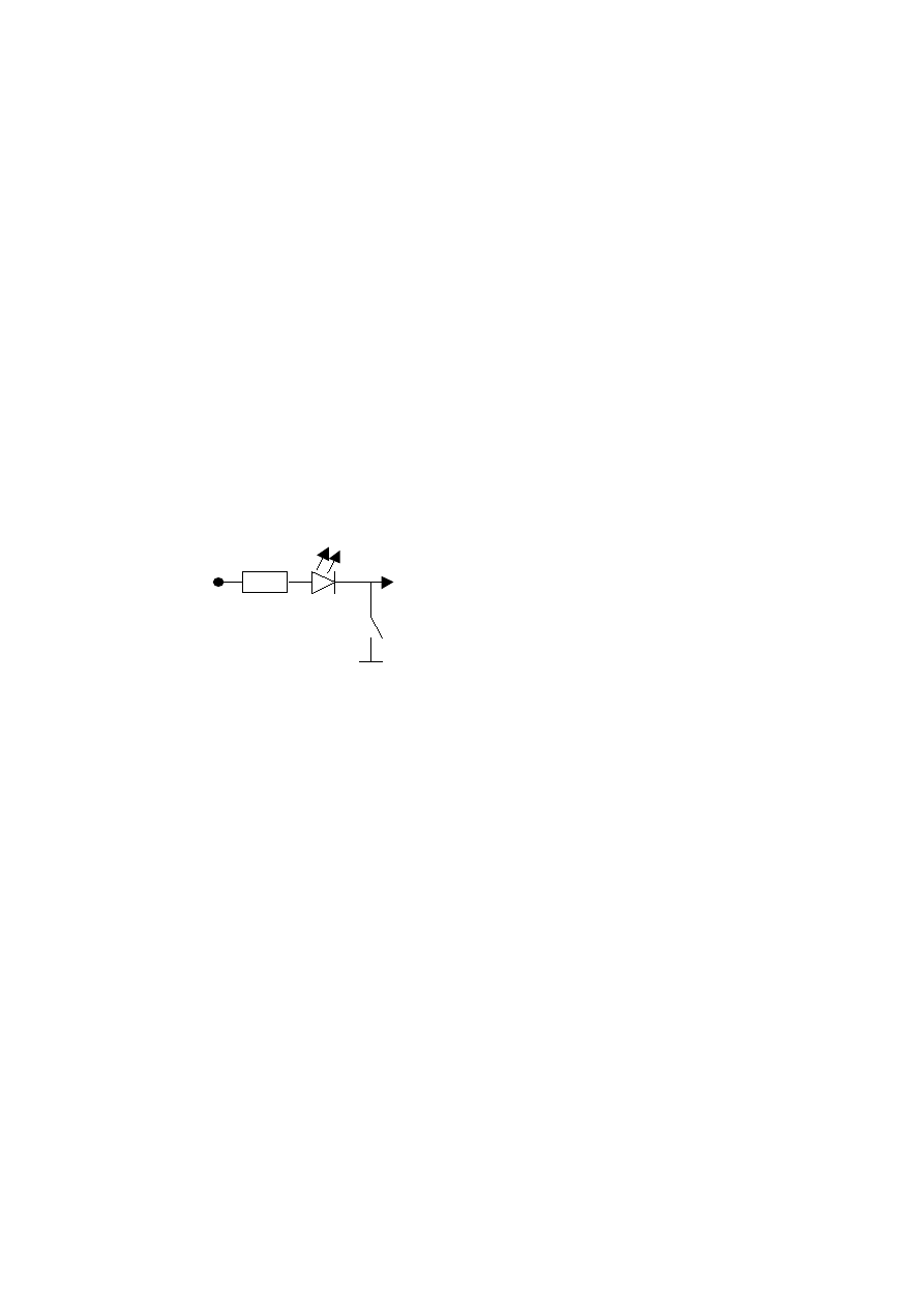
The following circuit can be used to read out the diagnostic codes.
To start readout of the codes:
1. Connect the circuit above, with the switch opened.
2. Turn on ignition
3. Within 3 seconds close the switch for 3-5 seconds, and open it again
4. The start code 12 will apear. Blink, pause, blink,blink.
5. Press the switch again for 3-5 seconds, and open it again.
6a. Now the diagnostic codes will follow in case there is an error code stored.
6b. If no more codes are stored the end code 11 will apear. Blink, pause, blink.
7a repeat step 5 and 6 until all codes are read out
7b After the end code you can clear all codes.
To clear all stored error codes:
1. First read out all codes described above
2. After the end code, close the switch for excactly 15 seconds.
3. Open the switch again
4. Now all stored codes are cleared.
All diagnostic connectors are located in the right hand side of the car in the large black box.
The cover can easily be removed by first removing the front cover exposing the relais followed
by the top cover. This will expose the ECU's. From front to back the following ECU's can be
found (dependant on the equipment installed) Hydroactive I or II, Engine ECU, ABS ECU. The
diagnostic connectors can be found floating arround in the ECU compartment, and can be
identified by their color. The diagnostic connectors are protected by a cover which can be
removed.
I'm unsure from what, till what time the large 30 pins diagnostic connector is used. The
connector is 3 pins wide and 10 pins long with the connector housing being brown. The pins
are numbered 1,2,3 from top to bottom and A,B,C….,I,J from left to right.
In case the large 30 pins diagnostic connector is present only a wire to connect the diagnostic
pin to ground is needed. The readout will work via the diagnostic lights on the dashboard. (In
case it doesn't work, one can always revert back to the circuit described above.)
Alternatively you can erase all error codes by disconnecting the battery for 10 (or more)
minutes. This will not only clear the codes, but also erase the 'learned' settings (eg for the
engine) and refer back to factory default.
+12 V
switch
680 Ohm
LED
To diag-
nostics pin
GND
( - of battery)

To test engine components:
Don't use this if you don't know what you are doing!!
1. Be sure ignition is turned off.
2. Close the switch
3. Turn on ignition
4. Within 1-12 seconds open the switch again
5. Wait some seconds
6. First code 91 will appear. Meaning the fuel pump will be activated periodically.
7. Close the switch for 3-5 seconds to test the next component.
8. Repeat until you arrived at the component which you want to test.
To tune the engine ecu:
1. Be sure ignition is turned off.
2. Close the switch
3. Turn on ignition
4. Within 1-12 seconds open the switch again
5. Within 3 seconds close the switch again for 3-5 seconds.
6. Open the switch for 3 seconds (5 max)
7. Close the switch again for 3-5 seconds.
8. Open the switch again.
9. The ECU should indicate code 22 by blinking. Meaning program start.
10. Enter code 2 by means of close 5 secs, open 3 secs, close 5 secs, open again.
11. The ECU will return 12 by blinking. Meaning 4 degrees ignition advance.
12. Close switch for 10-20 seconds. ECU will indicate code 11, meaning 2 degrees earlier.
Regretfully I don't have more data on this.
Don't use this if you don't know what you are doing!! (I never tried it, so I don't guarantee it will
work. It should work however on a Fenix 3B ecu (3.0 V6-12)

Code Description
Check
Comp
****
ECU XM Magneti Marelli G5
***
11 End test
***
12 Start test
***
13 Injection air temp sensor
4k@10C; 2,5k@20C; 680@55C
907
14 Cooling water temp sensor
4k@10C; 2,5k@20C; 680@55C; 230@90C
909
21 Throttle spindle potentiometer
4,5V max swing on pin 2
770
22
432
23 Idle speed control failure
31
900
33 Inlet manifold air pressure sensor
903
34
430
41 Engine speed sensor
152
42 Fuel injector
Check resistance of injector. 1.5 Ohm
570
45 Ignition coil 1-4
52 Air/fuel mixture control loop
54 ECU malfunction
142
57 Ignition coil 2-3
XM 2.0 RDZ XU10M Monopoint
XM 2.0 R6A XU10J2 Monopoint (from '91)
Idling actuator / Idle speed
regulator
Automatic adjustment air/fuel
ratio
oxygen/lambda sensor too quick (disconnect heater
element to resolve)
170 hPA : 0.25V, 1040 hPA : 4.8V between pin 9
and 12 (gnd) on ECU
Canister discharge valve (active
carbon filter)
345 Ohm between pin 14 and 31; check isolation to
ground
Check voltage between pin 1 and ground, should be
+12V. Check primary windings should be 1.4 Ohm
(between pin 1 and 4 on coil), secondary 8.6kOhm
(Valeo) or 14kOhm (Bosch)
inlet or outlet manifold leak or lambda-sensor
failure
Check voltage between pin 2 and ground, should be
+12V. Check primary windings should be 1.4 Ohm
(between pin 2 and 4 on coil), secondary 8.6kOhm
(Valeo) or 14kOhm (Bosch)

Code Description
Check
Comp
****
ECU XM Bosch Motronic MP3.1
***
11 End test
***
12 Start test
***
13 Injection air temp sensor
4k@10C; 2,5k@20C; 680@55C
907
14 Cooling water temp sensor
4k@10C; 2,5k@20C; 680@55C; 230@90C
909
21 Throttle spindle potentiometer
Closed 0.5V, fully open 4.5V (minimal)
770
22
432
31
900
33 Inlet manifold air pressure sensor
34
430
41 Engine speed sensor
152
51 Oxygen/lambda sensor
900
52 Air/fuel mixture control loop
53 Sensor power supply
54 ECU malfunction
142
XM 2.0 RFZ XU10J2/Z Multipoint (till jun-93)
Idling actuator / Idle speed
regulator
Automatic adjustment air/fuel
ratio
Check ogygen sensor, inlet&outlet manifold on
leakage, fuel pressure, fuel injectors, spark plugs,
air filter element, compression.
Is integrated in the ECU and cannot be checked.
Check vacuum hose to ECU.
Canister discharge valve (active
carbon filter)
245 Ohm between pin 23 and 25; check isolation to
ground
When engine hot and running should constantly
change from 0 to 1V measured between pin 24 and
pin 8.
inlet or outlet manifold leak or lambda-sensor
failure
Pin 16 and 5 should be connected to ground. Pin 18
should have +12V.

Code Description
Check
Comp
****
ECU XM Bosch Motronic MP3.2
***
11 End test
***
12 Start test
***
13 Injection air temp sensor
4k@10C; 2,5k@20C; 680@55C
907
14 Cooling water temp sensor
4k@10C; 2,5k@20C; 680@55C; 230@90C
909
21 Throttle spindle potentiometer
Closed 0.5V, fully open 4.5V (minimal)
770
22
432
31
900
33 Inlet manifold air pressure sensor
34
430
41 Engine speed sensor
152
43 Engine knock control loop
correct fuel grade, mechanical state engine
44 Anti-knock sensor
Check mounting of sensor (torque: 20Nm)
150
51 Oxygen/lambda sensor
900
52 Air/fuel mixture control loop
53 Sensor power supply
54 ECU malfunction
142
65 Sensor reference cylinder
71 Fuel injector 1
72 Fuel injector 2
73 Fuel injector 3
74 Fuel injector 4
XM 2.0 Turbo RGY or RGX XU10J2T/Z/L/L3
Multipoint
Warning: Not checked against
actual schematics!
Idling actuator / Idle speed
regulator
Automatic adjustment air/fuel
ratio
Check ogygen sensor, inlet&outlet manifold on
leakage, fuel pressure, fuel injectors, spark plugs,
air filter element, compression.
Is integrated in the ECU and cannot be checked.
Check vacuum hose to ECU.
Canister discharge valve (active
carbon filter)
330 Ohm between pin 48 and 49; check isolation to
ground
When engine hot and running should constantly
change from 0 to 1V measured between pin 28 and
pin 10.
inlet or outlet manifold leak or lambda-sensor
failure
Check fuel injector resistance. Should be 16 Ohm
each.
Check fuel injector resistance. Should be 16 Ohm
each.
Check fuel injector resistance. Should be 16 Ohm
each.
Check fuel injector resistance. Should be 16 Ohm
each.

Code Description
Check
Comp
****
ECU XM Bosch Motronic MP5.1
XM 2.0 RFZ XU10J2/Z Multipoint (from jul-93)
***
11 End test
***
12 Start test
***
13 Injection air temp sensor
4k@10C; 2,5k@20C; 680@55C
907
14 Cooling water temp sensor
4k@10C; 2,5k@20C; 680@55C; 230@90C
909
21 Throttle spindle potentiometer
Closed 0.5V, fully open 4.5V (minimal)
770
22
432
31
900
33 Inlet manifold air pressure sensor
903
34
430
41 Engine speed sensor
152
42 Fuel injectors
570
51 Oxygen/lambda sensor
900
52 Air/fuel mixture control loop
53 Sensor power supply
54 ECU malfunction
142
Idling actuator / Idle speed
regulator
Automatic adjustment air/fuel
ratio
Check ogygen sensor, inlet&outlet manifold on
leakage, fuel pressure, fuel injectors, spark plugs,
air filter element, compression.
Is integrated in the ECU and cannot be checked.
Check vacuum hose to ECU.
Canister discharge valve (active
carbon filter)
320-340 Ohm between pin 11 and 30; check
isolation to ground
Check resistance of each injector. Should be 16
Ohm each.
When engine hot and running should constantly
change from 0 to 1V measured between pin 28 and
pin 10.
inlet or outlet manifold leak or lambda-sensor
failure
Pin 19, 2 and 14 should be connected to ground.
Pin 18, 37 should have +10-15.5V on them (+ from
battery)

Code Description
Check
Comp
****
ECU XM Bosch Motronic MP5.1.1 XM 2.0 RFV XU10J4R/L/L3 (16V) Multiploint
***
11 End test
***
12 Start test
***
13 Injection air temp sensor
4k@10C; 2,5k@20C; 680@55C
907
14 Cooling water temp sensor
4k@10C; 2,5k@20C; 680@55C; 230@90C
909
21 Throttle spindle potentiometer
Closed 0.5V, fully open 4.5V (minimal)
770
22
432
27 Vehicle speed sensor
154
31
900
33 Inlet manifold air pressure sensor
903
34
430
41 Engine speed sensor
152
42 Fuel injectors
570
43 Engine knock control loop
correct fuel grade, mechanical state engine
44 Anti-knock sensor
Check mounting of sensor (torque: 20Nm)
150
51 Oxygen/lambda sensor
900
52 Air/fuel mixture control loop
53 Sensor power supply
54 ECU malfunction
142
Idling actuator / Idle speed
regulator
R=300 Ohm on sensor; When driving a speed
relative signal on pin 9
Automatic adjustment air/fuel
ratio
Check ogygen sensor, inlet&outlet manifold on
leakage, fuel pressure, fuel injectors, spark plugs,
air filter element, compression.
Is integrated in the ECU and cannot be checked.
Check vacuum hose to ECU.
Canister discharge valve (active
carbon filter)
320-340 Ohm between pin 11 and 30; check
isolation to ground
Check resistance of each injector. Should be 16
Ohm each.
When engine hot and running should constantly
change from 0 to 1V measured between pin 28 and
pin 10.
inlet or outlet manifold leak or lambda-sensor
failure
Pin 19, 2 and 14 should be connected to ground.
Pin 18, 37 should have +10-15.5V on them (+ from
battery)

Code Description
Check
Comp
****
ECU XM V6 Fenix 3B
***
11 End test
***
12 Start test
***
13 Injection air temp sensor
4k@10C; 2,5k@20C; 680@55C
907
14 Cooling water temp sensor
4k@10C; 2,5k@20C; 680@55C; 230@90C
909
15 Fuel pump relais
807
21 Throttle spindle potentiometer
4,5V max swing on pin 9
770
22
432
23
0,5 +/- 0,1V between pin 9 and 17 (gnd)
770
27 Vehicle speed sensor
154
31
900
33 Inlet manifold air pressure sensor
903
34
430
36
818
41 Engine speed sensor
152
42 Fuel injectors
570
43 Engine knock control loop
correct fuel grade, mechanical state engine
44 Front anti-knock sensor
150
51 Oxygen/lambda sensor
900
52 Air/fuel mixture control loop
inlet or outlet manifold leak
53 Sensor power supply
10-15,5V on pin 4 ECU from gnd (pin 1).
54 ECU malfunction
142
56 Anti-theft start code not entered
176
62 Rear anti-knock sensor
151
Idling actuator / Idle speed
regulator
Throttle spindle potentiometer
idle value
R=300 Ohm on sensor; When driving 1,5Volt on pin
3
Automatic adjustment air/fuel
ratio
oxygen/lambda sensor too quick (disconnect heater
element to resolve)
400Pa=2,5V; 600Pa=1,25V between pin 33 and 17
(gnd)
Canister discharge valve (active
carbon filter)
Relais oxygen/lambda sensor
heater
330 Ohm between pin 11 and 28; check isolation to
ground
14 Ohm each injector (2-3 Ohm between pin 20/21
and pin 30)
When engine hot and running should constantly
change from 0 to 1V on pin 35 from pin 32 (gnd)

Code Description
Comp
****
ECU XM V6 Fenix 3B (activate components)
****
Component activation is performed
91 Activate fuel pump relais
807
92 Activate fuel injectors
570
93 Activate idling actuator
432
94 Activate canister discharge valve
430
95 Activate relais airco compressor
822
****
ECU XM V6 Fenix 3B (Mixture adjustment)
****
11 Make mixture richer
22 Make mixture leaner
33 Program start
99 upper or lower limit reached
****
ECU XM V6 Fenix 3B (Ignition timing adjustment)
****
11 2 degrees advance
12 4 degrees advance
13 6 degrees advance
14 8 degrees advance
19 default setting
22 Program start
99 upper or lower limit reached

Code Description
Check
Comp
****
ECU Hydroactive I/II suspension Version HI and HII pinning are totally different.
****
11 End test
***
12 Start test
***
21 Brake pressure switch
670
22
771
23 Steering wheel position sensor
159
24 Vehicle speed sensor
154
25 Vehicle height sensor
153
31 Electrovalve firm/soft suspension
433
32
53 ECU powersupply
HI: check fuse 34. HII: check fuse 7.
54 ECU malfunction
Switch will open when firm brake pressure applied
(HI measure between pin 7 white and ground, HII
between pin 11 black and gnd)
Accelerator pedal position
potentiometer (situated under
pedal)
Pedal up=3-4V; pedal down<3V. HI measure
between pin 10 white and ground. HII between pin
4 black and ground.
Will alternate between 0 and +5V when slowly
moving steering wheel. HI: Measure on both on
pins 6 and 13 white to pin 12 white which is
ground. HII: pin 9,10,15 black and 13 white are for
steering wheel sensor. Two pins for position, other
two for power supply and ground.
HI: R=300 Ohm on speed sensor, when driving ca
1,5V on pin 13 black. HII: measure speed signal on
pin 11 white.
Will alternate between 0 and +5V when vehicle
height is changed. HI: Measure on both on pins 3
and 4 black to ground. HII measure on both pins
13 and 14 black to ground.
R=3-5 Ohm, when valve is operated suspension is
soft. HI: Measure between pin 9 black and ground.
HII: Measure between pin 1 white and ground.
When valve is acivated measure 12 volt, followed
by an alternating signal at a few hundred Hertz.
Back electrovalve firm/soft
suspension
Only present on Hydroactive II. R=3-5 Ohm, when
valve is operated suspension is soft. HII: Measure
between pin 2 white and ground. When valve is
acivated measure 12 volt, followed by an
alternating signal at a few hundred Hertz.

Code Description
Check
Comp
****
ECU ABS (Teves version)
11
End test
***
12
Start test
***
13
Electrovalves supply
41
15
Electrovalves relais.
41
21
Electrovalves relais.
41
22
Electrovalves relais.
24
LH rear wheel sensor
157
25
RH front wheel sensor
156
31
RH rear wheel sensor
158
32
LH front wheel sensor
155
33
LH rear wheel sensor signal
157
34
RH front wheel sensor signal
156
35
RH rear wheel sensor signal
158
41
LH front wheel sensor signal
155
42
Electrovalve RH front inlet
41
43
Electrovalve RH front return
41
44
Electrovalve LH front inlet
41
45
Electrovalve LH front return
41
51
Electrovalve rear
41
55
Error in ECU memory
140
Teves version is with two seperature units, Bendix
has valves and ecu integrated.
check resistance on electrovalves 2-4Ohm each.
Pin 1,2,3,4,5 on 7 pin connector against pin 5 on 5
pin connector
Check resistance between pin 2 and 3 on 5 pin
connector 50-60Ohm
Check resistance between pin 2 and 3 on 5 pin
connector 50-60Ohm
Check wiring to electrovalves on shortcircuit or
loose connection
Measure R=1-1,4kOhm (after 3-94 R=2,2-
3,2kOhm), between pin 15 and 32 on ECU
Measure R=1-1,4kOhm (after 3-94 R=2,2-
3,2kOhm), between pin 16 and 33 on ECU
Measure R=1-1,4kOhm (after 3-94 R=2,2-
3,2kOhm), between pin 17 and 34 on ECU
Measure R=1-1,4kOhm (after 3-94 R=2,2-
3,2kOhm), between pin 18 and 35 on ECU
Check signal, check air-gap between teeth-sensor,
check teeth condition
Check signal, check air-gap between teeth-sensor,
check teeth condition
Check signal, check air-gap between teeth-sensor,
check teeth condition
Check signal, check air-gap between teeth-sensor,
check teeth condition
Check resistance of electrovalve between pin 2 on
7 pin connector and pin 5 on 5 pin connector
Check resistance of electrovalve 2-4 Ohm between
pin 4 on 7 pin connector and pin 5 on 5 pin
connector
Check resistance of electrovalve 2-4 Ohm between
pin 3 on 7 pin connector and pin 5 on 5 pin
connector
Check resistance of electrovalve 2-4 Ohm between
pin 5 on 7 pin connector and pin 5 on 5 pin
connector
Check resistance of electrovalve 2-4 Ohm between
pin 1 on 7 pin connector and pin 5 on 5 pin
connector

Code Description
Check
****
ECU ABS (Bendix version)
11
End test
12
Start test
13
Electrovalves supply
15
Electrovalves relais.
Check Relais
21
Electrovalves relais.
Check Relais
22
Electrovalves relais.
Check Relais
24
LH rear wheel sensor
25
RH front wheel sensor
31
RH rear wheel sensor
32
LH front wheel sensor
33
LH rear wheel sensor signal
34
RH front wheel sensor signal
35
RH rear wheel sensor signal
41
LH front wheel sensor signal
42
Electrovalve RH front inlet
43
Electrovalve RH front return
44
Electrovalve LH front inlet
45
Electrovalve LH front return
51
Electrovalve rear
55
Error in ECU memory
Teves version is with two seperature units, Bendix
has valves and ecu integrated.
Measure R=1-1,4kOhm (Bendix type) or R=2,2-
3,2kOhm (Bendix/Siemens type), between pin 19
and 28 on ECU
Measure R=1-1,4kOhm (Bendix type) or R=2,2-
3,2kOhm (Bendix/Siemens type), between pin 1
and 6 on ECU
Measure R=1-1,4kOhm (Bendix type) or R=2,2-
3,2kOhm (Bendix/Siemens type), between pin 29
and 31 on ECU
Measure R=1-1,4kOhm (Bendix type) or R=2,2-
3,2kOhm (Bendix/Siemens type), between pin 15
and 30 on ECU
Check signal, check air-gap between teeth-sensor,
check teeth condition
Check signal, check air-gap between teeth-sensor,
check teeth condition
Check signal, check air-gap between teeth-sensor,
check teeth condition
Check signal, check air-gap between teeth-sensor,
check teeth condition

Code Description
Check
Comp
****
11
End test
***
12
Start test
***
13
710
14
710
15
711
16
711
17
710
18
700
21
700
22
700
23
912
24
912
25
908
26
908
27
Full automatic only. Electrovalve on blower unit?
711
31
Interior temperature sensor signal
913
32
913
33
681
34
Semi auto only.
681
35
700
36
700
41
183
42
183
ECU Airconditioning (Full
automatic, Semi automatic
with/without airco)
Airflow direction valve position
potentiometer signal
Full auto only; pin 3 black voltage should vary when
changing vent position.
Airflow direction valve position
potentiometer short-circuit
Recirculation valve position
potentiometer signal
Full auto only; pin 4 black voltage should change
when changing recirculation.
Recirculation valve position
potentiometer short-circuit
Airflow direction valve position
signal swing not correct
Full automatic only. Electrovalve on RH side of
mid-console.
Hot air/cold air control valve
position signal swing not correct.
Full automatic only. Electrovalve on LH side of mid-
console.
Hot air/cold air control valve
position potentiometer signal
Full auto: pin 15 black. Other: pin 3 blue. Signal
should vary when changing temperature between
min and max.
Hot air/cold air control valve
position potentiometer short-
circuit
Evaporator temperature sensor
signal
Full auto: Between pin 14 black and pin 1 black.
Semi auto: Between pin 2 blue and pin 1 black.
R=10k@10C; 6k@20C; 5k@25C; 4k@30C
Evaporator temperature sensor
short-circuit
Outdoor temperature sensor
signal
In air-inlet. Full auto: Between pin 13 black and pin
1 black. Semi auto: Between pin 1 blue and pin 1
black. R=20k@10C; 12,5k@20C; 10k@25C;
8k@30C
Outdoor temperature sensor
short-circuit
Recirculation valve position signal
swing not correct
Full auto: Between pin 10 blue and pin 1 black.
Semi auto: Between pin 5 black and pin 1 black.
R=20k@10C; 12,5k@20C; 10k@25C; 8k@30C
Interior temperature sensor short-
ciruit
Interior air blower motor signal
line interrupted
Semi auto only. If only highest speed works, check
transistors on control module on blower motor.
Interior air blower motor signal
line short-circuit
Hot air/cold air flap motor line
interrupted
Full auto: Between pin 6 and 7 black. Semi auto:
Between pin 9 and 10 blue. R=50Ohm.
Hot air/cold air flap motor line
short-circuit
See fault 35. Typical fault are worn motor brushes,
which cause short-circuit. Can be solved by
reshaping brushes (eg. with a knife).
Air blower speed potentiometer
signal interrupted
Semi auto only. Visually check potentiometer track
on pcb.
Air blower speed potentiometer
signal short-circuited
Semi auto only. Visually check potentiometer track
on pcb.

43
182
44
182
46
255
51
711
52
711
53
710
54
710
55
916
56
916
63
681
64
Full auto only.
681
Temperature selection
potentiometer signal signal
interrupted
Semi auto only. Visually check potentiometer track
on pcb.
Temperature selection
potentiometer signal signal short-
circuit
Semi auto only. Visually check potentiometer track
on pcb.
Airco compressor electro-
magnetic clutch
Full and semi auto: pin 2 white. Check if short
circuit in wiring.
Recirculation flap motor line
interrupted?
Full auto only. Between pin 8 and 9 black measure
R=50Ohm.
Recirculation flap motor line
short-circuit?
See fault 51. Typical fault are worn motor brushes,
which cause short-circuit. Can be solved by
reshaping brushes (eg. with a knife).
Airflow direction flap motor line
interrupted
Full auto only. Between pin 10 and 11 black
measure R=50Ohm.
Airflow direction flap motor line
short-circuit
See fault 53. Typical fault are worn motor brushes,
which cause short-circuit. Can be solved by
reshaping brushes (eg. with a knife).
Cooling water temperature sensor
signal
Full auto only. Measure between pin 11 blue and
pin 1 black.
Cooling water temperature sensor
short-circuit
Interior air blower motor signal
line interrupted
Full auto only. If only highest speed works, check
transistors on control module on blower motor.
Interior air blower motor signal
line short-circuit
Wyszukiwarka
Podobne podstrony:
ECU codes and how to read them out
10 killer job interview questions and how to answer them
Compressors And How To Use Them
101 Project Management Problems and How to Solve Them 2011
Jack M Bickham 38 Most Common Fiction Writing Mistakes and how to avoid them
Your Forces and How to Use Them Christian D Larson
Secrets and How to Keep Them
Body Lang How to Read and Make Body Movements for Maximum Success
Wind Chimes and Water Fountains Favorite Feng Shui Objects & How To Use Them
TTC How to Read and Understand Poetry, Course Guidebook I
TTC How to Read and Understand Poetry, Course Guidebook II
How to read the equine ECG id 2 Nieznany
How To Read Body Language www mixtorrents blogspot com
how to write a?out myself ZYABIJX2VR2TZRXPUC6NLNLC32TN6MBN6Q5AEOI
How to read maths
The crime of bad Power Point and how to avoid it
How to read the equine ECG id 2 Nieznany
How To Read Body Language www mixtorrents blogspot com
how to 080206 ask out quiz
więcej podobnych podstron