
MIR-1
DRIVER CONTROLS
C
D
E
F
G
H
I
J
K
M
SECTION
MIR
A
B
MIR
N
O
P
CONTENTS
MIRRORS
DTC/CIRCUIT DIAGNOSIS ..........................
DOOR MIRROR ...................................................
Description ................................................................
Wiring Diagram - MIRROR SYSTEM - ......................
Component Inspection ..............................................
SYMPTOM DIAGNOSIS ...............................
Work Flow .................................................................
Inspection Procedure ................................................
Diagnostic Worksheet .............................................
PRECAUTION ..............................................
PRECAUTIONS ..................................................
PREPARATION ...........................................
PREPARATION ..................................................
Commercial Service Tools .....................................
REMOVAL AND INSTALLATION ...............
INSIDE MIRROR ...............................................
Exploded View .........................................................
Removal and Installation .........................................
OUTSIDE MIRROR ...........................................
DOOR MIRROR ASSEMBLY ....................................
DOOR MIRROR ASSEMBLY : Exploded View .......
GLASS MIRROR ........................................................
GLASS MIRROR : Exploded View ..........................
GLASS MIRROR : Disassembly and Assembly ......
DOOR MIRROR COVER ...........................................
DOOR MIRROR COVER : Exploded View ..............
DOOR MIRROR REMOTE CONTROL
SWITCH .............................................................
Exploded View .........................................................
Removal and Installation .........................................
Revision: 2009 March
2009 Z12

MIR-2
< DTC/CIRCUIT DIAGNOSIS >
DOOR MIRROR
DTC/CIRCUIT DIAGNOSIS
DOOR MIRROR
Description
INFOID:0000000005131714
Component
Function
Door mirror remote control
switch
Mirror switch
It supplies power to mirror motor through mirror switch and changeover
switch.
Changeover switch
It transmits the LH/RH control of door mirror that supplies power.
Door mirror
Door mirror motor
It makes mirror face operate from side to side and up and down via inte-
grated motor.
Revision: 2009 March
2009 Z12
DOOR MIRROR
MIR-3
< DTC/CIRCUIT DIAGNOSIS >
C
D
E
F
G
H
I
J
K
M
A
B
MIR
N
O
P
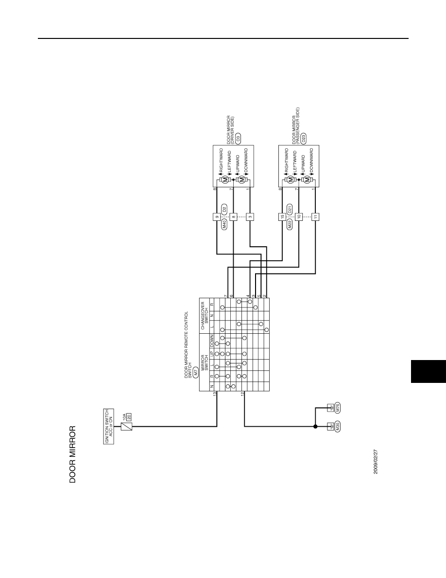
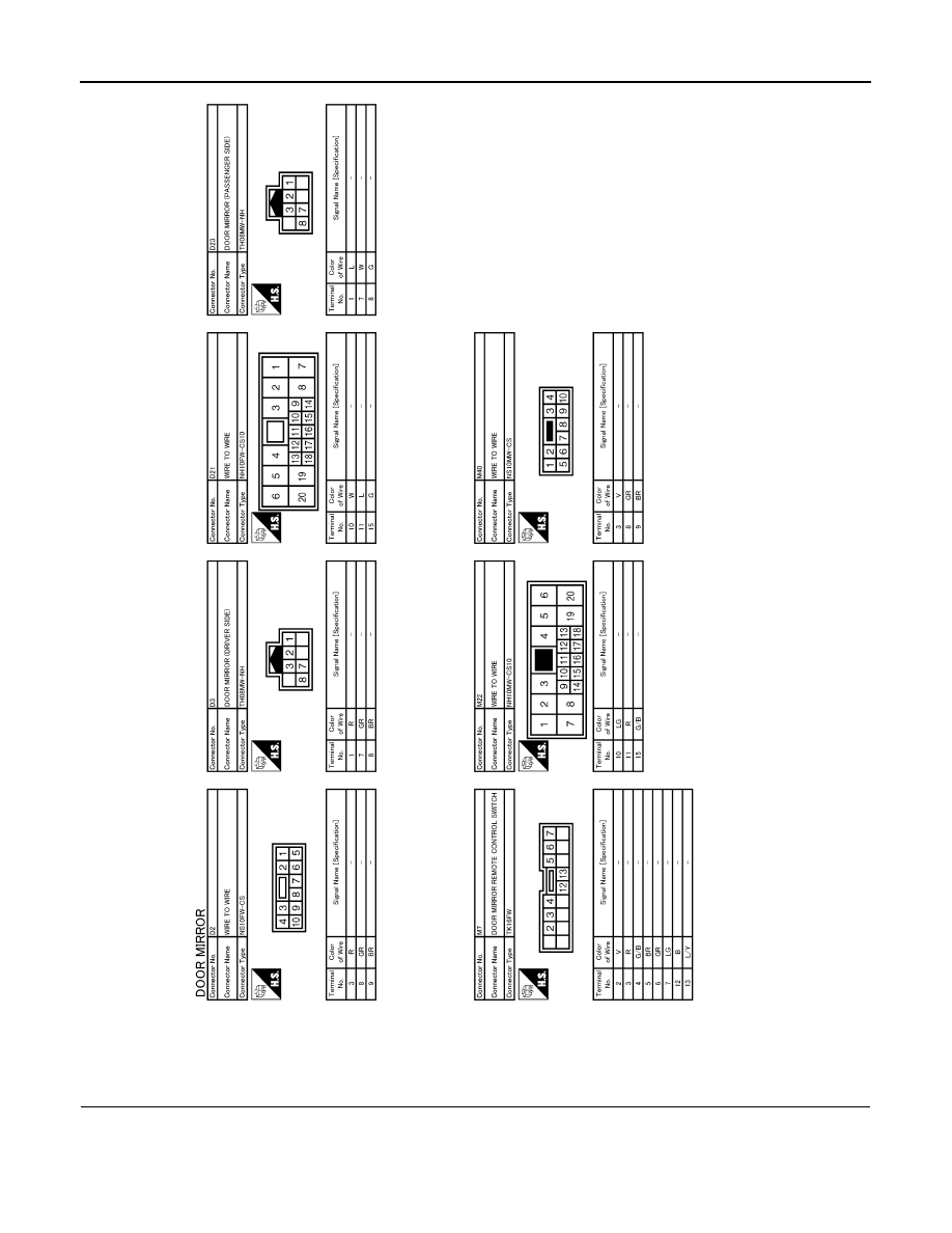
Wiring Diagram - MIRROR SYSTEM -
INFOID:0000000005070063
JCLWM3482GB
Revision: 2009 March
2009 Z12
MIR-4
< DTC/CIRCUIT DIAGNOSIS >
DOOR MIRROR
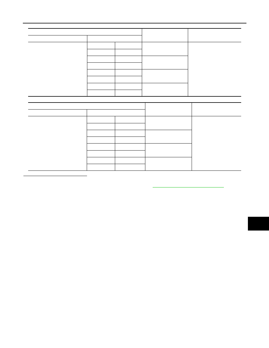
Component Inspection
INFOID:0000000005131715
1.
CHECK DOOR MIRROR REMOTE CONTROL SWITCH
1.
Turn ignition switch OFF.
2.
Disconnect door mirror remote control switch connector.
3.
Check door mirror remote control switch.
JCLWM3483GB
Revision: 2009 March
2009 Z12
DOOR MIRROR
MIR-5
< DTC/CIRCUIT DIAGNOSIS >
C
D
E
F
G
H
I
J
K
M
A
B
MIR
N
O
P
[Door mirror (driver side)]
[Door mirror (passenger side)]
Is the inspection result normal?
YES
>> INSPECTION END.
NO
>> Replace door mirror remote control switch.Refer to
MIR-19, "Removal and Installation"
.
Door mirror remote control switch
Mirror switch condition
Continuity
Connector
Terminal
M7
13
6
RIGHT
Existed
12
5
13
5
LEFT
12
6
13
2
UP
12
6
13
6
DOWN
12
2
Door mirror remote control switch
Mirror switch condition
Continuity
Connector
Terminal
M7
13
7
RIGHT
Existed
12
4
13
4
LEFT
12
7
13
3
UP
12
7
13
7
DOWN
12
3
Revision: 2009 March
2009 Z12
MIR-6
< SYMPTOM DIAGNOSIS >
SQUEAK AND RATTLE TROUBLE DIAGNOSES
SYMPTOM DIAGNOSIS
SQUEAK AND RATTLE TROUBLE DIAGNOSES
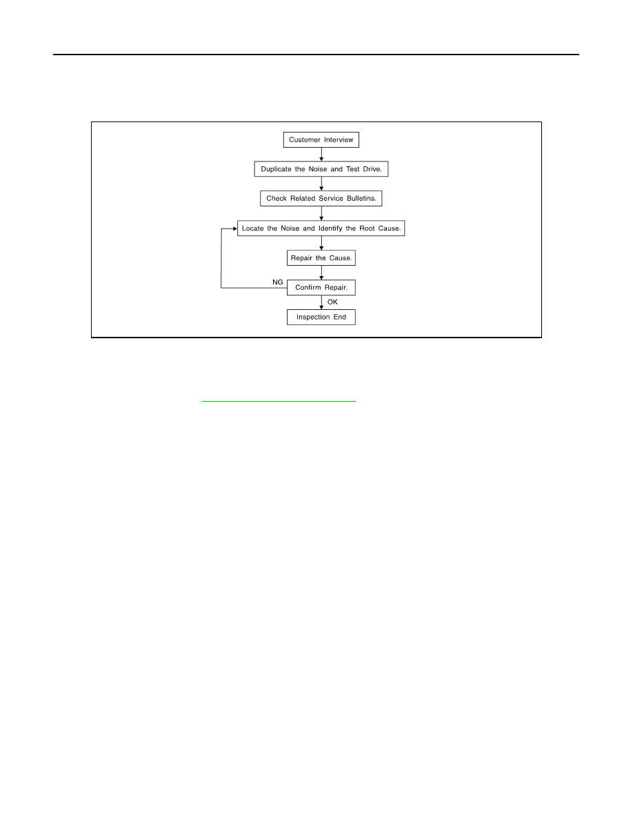
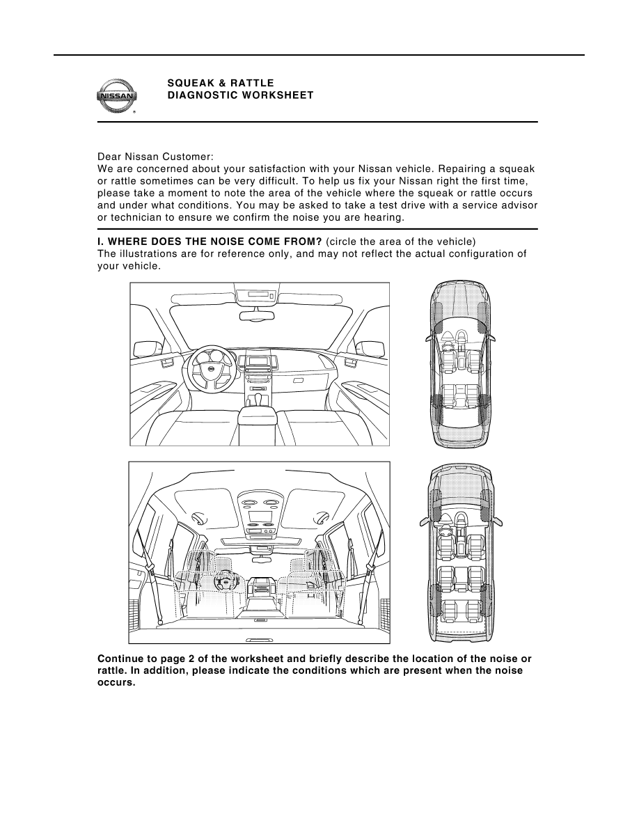
Work Flow
INFOID:0000000005187570
CUSTOMER INTERVIEW
Interview the customer if possible, to determine the conditions that exist when the noise occurs. Use the Diag-
nostic Worksheet during the interview to document the facts and conditions when the noise occurs and any of
customer's comments; refer to
MIR-10, "Diagnostic Worksheet"
. This information is necessary to duplicate the
conditions that exist when the noise occurs.
• The customer may not be able to provide a detailed description or the location of the noise. Attempt to obtain
all the facts and conditions that exist when the noise occurs (or does not occur).
• If there is more than one noise in the vehicle, perform a diagnosis and repair the noise that the customer is
concerned about. This can be accomplished by performing a cruise test on the vehicle with the customer.
• After identifying the type of noise, isolate the noise in terms of its characteristics. The noise characteristics
are provided so the customer, service adviser and technician are all speaking the same language when
defining the noise.
• Squeak – (Like tennis shoes on a clean floor)
Squeak characteristics include the light contact/fast movement/brought on by road conditions/hard surfaces
= higher pitch noise/softer surfaces = lower pitch noises/edge to surface = chirping
• Creak – (Like walking on an old wooden floor)
Creak characteristics include firm contact/slow movement/twisting with a rotational movement/pitch depen-
dent on materials/often brought on by activity.
• Rattle – (Like shaking a baby rattle)
Rattle characteristics include the fast repeated contact/vibration or similar movement/loose parts/missing
clip or fastener/incorrect clearance.
• Knock – (Like a knock on a door)
Knock characteristics include hollow sounding/sometimes repeating/often brought on by driver action.
• Tick – (Like a clock second hand)
Tick characteristics include gentle contacting of light materials/loose components/can be caused by driver
action or road conditions.
• Thump – (Heavy, muffled knock noise)
Thump characteristics include softer knock/dead sound often brought on by activity.
• Buzz – (Like a bumblebee)
Buzz characteristics include high frequency rattle/firm contact.
• Often the degree of acceptable noise level will vary depending up on the person. A noise that a technician
may judge as acceptable may be very irritating to the customer.
• Weather conditions, especially humidity and temperature, may have a great effect on noise level.
DUPLICATE THE NOISE AND TEST DRIVE
SBT842
Revision: 2009 March
2009 Z12

SQUEAK AND RATTLE TROUBLE DIAGNOSES
MIR-7
< SYMPTOM DIAGNOSIS >
C
D
E
F
G
H
I
J
K
M
A
B
MIR
N
O
P
If possible, drive the vehicle with the customer until the noise is duplicated. Note any additional information on
the Diagnostic Worksheet regarding the conditions or location of the noise. This information can be used to
duplicate the same conditions when the repair is reconfirmed.
If the noise can be duplicated easily during the test drive, to help identify the source of the noise, try to dupli-
cate the noise with the vehicle stopped by doing one or all of the following:
1) Close a door.
2) Tap or push/pull around the area where the noise appears to be coming from.
3) Rev the engine.
4) Use a floor jack to recreate vehicle “twist”.
5) At idle, apply engine load (electrical load, half-clutch on M/T models, drive position on A/T models).
6) Raise the vehicle on a hoist and hit a tire with a rubber hammer.
• Drive the vehicle and attempt to duplicate the conditions the customer states exist when the noise occurs.
• If it is difficult to duplicate the noise, drive the vehicle slowly on an undulating or rough road to stress the
vehicle body.
CHECK RELATED SERVICE BULLETINS
After verifying the customer concern or symptom, check ASIST for Technical Service Bulletins (TSBs) related
to that concern or symptom.
If a TSB relates to the symptom, follow the procedure to repair the noise.
LOCATE THE NOISE AND IDENTIFY THE ROOT CAUSE
1.
Narrow down the noise to a general area. To help pinpoint the source of the noise, use a listening tool
(Chassis ear: J-39570, Engine ear and mechanics stethoscope).
2.
Narrow down the noise to a more specific area and identify the cause of the noise by:
• Removing the components in the area that is are suspected to be the cause of the noise.
Do not use too much force when removing clips and fasteners, otherwise clips and fastener can be broken
or lost during the repair, resulting in the creation of new noise.
• Tapping or pushing/pulling the component that is are suspected to be the cause of the noise.
Do not tap or push/pull the component with excessive force, otherwise the noise will be eliminated only tem-
porarily.
• Feeling for a vibration by hand by touching the component(s) that is are suspected to be the cause of the
noise.
• Placing a piece of paper between components that are suspected to be the cause of the noise.
• Looking for loose components and contact marks.
.
REPAIR THE CAUSE
• If the cause is a loose component, tighten the component securely.
• If the cause is insufficient clearance between components:
- Separate components by repositioning or loosening and retightening the component, if possible.
- Insulate components with a suitable insulator such as urethane pads, foam blocks, felt cloth tape or ure-
thane tape. A Nissan Squeak and Rattle Kit (J-43980) is available through the authorized Nissan Parts
Department.
CAUTION:
Never use excessive force as many components are constructed of plastic and may be damaged.
NOTE:
Always check with the Parts Department for the latest parts information.
The following materials are contained in the Nissan Squeak and Rattle Kit (J-43980). Each item can be
ordered separately as needed.
URETHANE PADS [1.5 mm (0.059 in) thick]
Insulates connectors, harness, etc.
76268-9E005: 100
×
135 mm (3.94
×
5.31 in)/76884-71L01: 60
×
85 mm (2.36
×
3.35 in)/76884-
71L02:15
×
25 mm (0.59
×
0.98 in)
INSULATOR (Foam blocks)
Insulates components from contact. Can be used to fill space behind a panel.
73982-9E000: 45 mm (1.77 in) thick, 50
×
50 mm (1.97
×
1.97 in)/73982-
50Y00: 10 mm (0.39 in) thick, 50
×
50 mm (1.97
×
1.97 in)
INSULATOR (Light foam block)
80845-71L00: 30 mm (1.18 in) thick, 30
×
50 mm (1.18
×
1.97 in)
FELT CLOTHTAPE
Used to insulate where movement does not occur. Ideal for instrument panel applications.
Revision: 2009 March
2009 Z12

MIR-8
< SYMPTOM DIAGNOSIS >
SQUEAK AND RATTLE TROUBLE DIAGNOSES
68370-4B000: 15
×
25 mm (0.59
×
0.98 in) pad/68239-13E00: 5 mm (0.20 in) wide tape roll
The following materials, not found in the kit, can also be used to repair squeaks and rattles.
UHMW (TEFLON) TAPE
Insulates where slight movement is present. Ideal for instrument panel applications.
SILICONE GREASE
Used in place of UHMW tape that is be visible or does not fit. Will only last a few months.
SILICONE SPRAY
Used when grease cannot be applied.
DUCT TAPE
Used to eliminate movement.
CONFIRM THE REPAIR
Confirm that the cause of a noise is repaired by test driving the vehicle. Operate the vehicle under the same
conditions as when the noise originally occurred. Refer to the notes on the Diagnostic Worksheet.
Inspection Procedure
INFOID:0000000005187571
Refer to Table of Contents for specific component removal and installation information.
INSTRUMENT PANEL
Most incidents are caused by contact and movement between:
1.
The cluster lid A and instrument panel
2.
Acrylic lens and combination meter housing
3.
Instrument panel to front pillar garnish
4.
Instrument panel to windshield
5.
Instrument panel mounting pins
6.
Wiring harnesses behind the combination meter
7.
A/C defroster duct and duct joint
These incidents can usually be located by tapping or moving the components to duplicate the noise or by
pressing on the components while driving to stop the noise. Most of these incidents can be repaired by
applying felt cloth tape or silicon spray (in hard to reach areas). Urethane pads can be used to insulate
wiring harness.
CAUTION:
Never use silicone spray to isolate a squeak or rattle. If the area is saturated with silicone, the
recheck of repair becomes impossible.
CENTER CONSOLE
Components to pay attention to include:
1.
Shifter assembly cover to finisher
2.
A/C control unit and cluster lid C
3.
Wiring harnesses behind audio and A/C control unit
The instrument panel repair and isolation procedures also apply to the center console.
DOORS
Pay attention to the following:
1.
Finisher and inner panel making a slapping noise
2.
Inside handle escutcheon to door finisher
3.
Wiring harnesses tapping
4.
Door striker out of alignment causing a popping noise on starts and stops
Tapping or moving the components or pressing on them while driving to duplicate the conditions can isolate
many of these incidents. The areas can usually be insulated with felt cloth tape or insulator foam blocks from
the Nissan Squeak and Rattle Kit (J-43980) to repair the noise.
TRUNK
Trunk noises are often caused by a loose jack or loose items put into the trunk by the customer.
In addition look for the following:
1.
Trunk lid dumpers out of adjustment
2.
Trunk lid striker out of adjustment
Revision: 2009 March
2009 Z12

SQUEAK AND RATTLE TROUBLE DIAGNOSES
MIR-9
< SYMPTOM DIAGNOSIS >
C
D
E
F
G
H
I
J
K
M
A
B
MIR
N
O
P
3.
The trunk lid torsion bars knocking together
4.
A loose license plate or bracket
Most of these incidents can be repaired by adjusting, securing or insulating the item(s) or component(s) caus-
ing the noise.
SUNROOF/HEADLINING
Noises in the sunroof/headlining area can often be traced to one of the following:
1.
Sunroof lid, rail, linkage or seals making a rattle or light knocking noise
2.
Sunvisor shaft shaking in the holder
3.
Front or rear windshield touching headlining and squeaking
Again, pressing on the components to stop the noise while duplicating the conditions can isolate most of these
incidents. Repairs usually consist of insulating with felt cloth tape.
SEATS
When isolating seat noise it's important to note the position the seats in and the load placed on the seat when
the noise occurs. These conditions should be duplicated when verifying and isolating the cause of the noise.
Cause of seat noise include:
1.
Headrest rods and holder
2.
A squeak between the seat pad cushion and frame
3.
The rear seatback lock and bracket
These noises can be isolated by moving or pressing on the suspected components while duplicating the con-
ditions under which the noise occurs.Most of these incidents can be repaired by repositioning the component
or applying urethane tape to the contact area.
UNDERHOOD
Some interior noise may be caused by components under the hood or on the engine wall. The noise is then
transmitted into the passenger compartment.
Causes of transmitted underhood noise include:
1.
Any component mounted to the engine wall
2.
Components that pass through the engine wall
3.
Engine wall mounts and connectors
4.
Loose radiator mounting pins
5.
Hood bumpers out of adjustment
6.
Hood striker out of adjustment
These noises can be difficult to isolate since they cannot be reached from the interior of the vehicle. The best
method is to secure, move or insulate one component at a time and test drive the vehicle. Also, engine RPM
or load can be changed to isolate the noise. Repairs can usually be made by moving, adjusting, securing, or
insulating the component causing the noise.
Revision: 2009 March
2009 Z12
MIR-10
< SYMPTOM DIAGNOSIS >
SQUEAK AND RATTLE TROUBLE DIAGNOSES
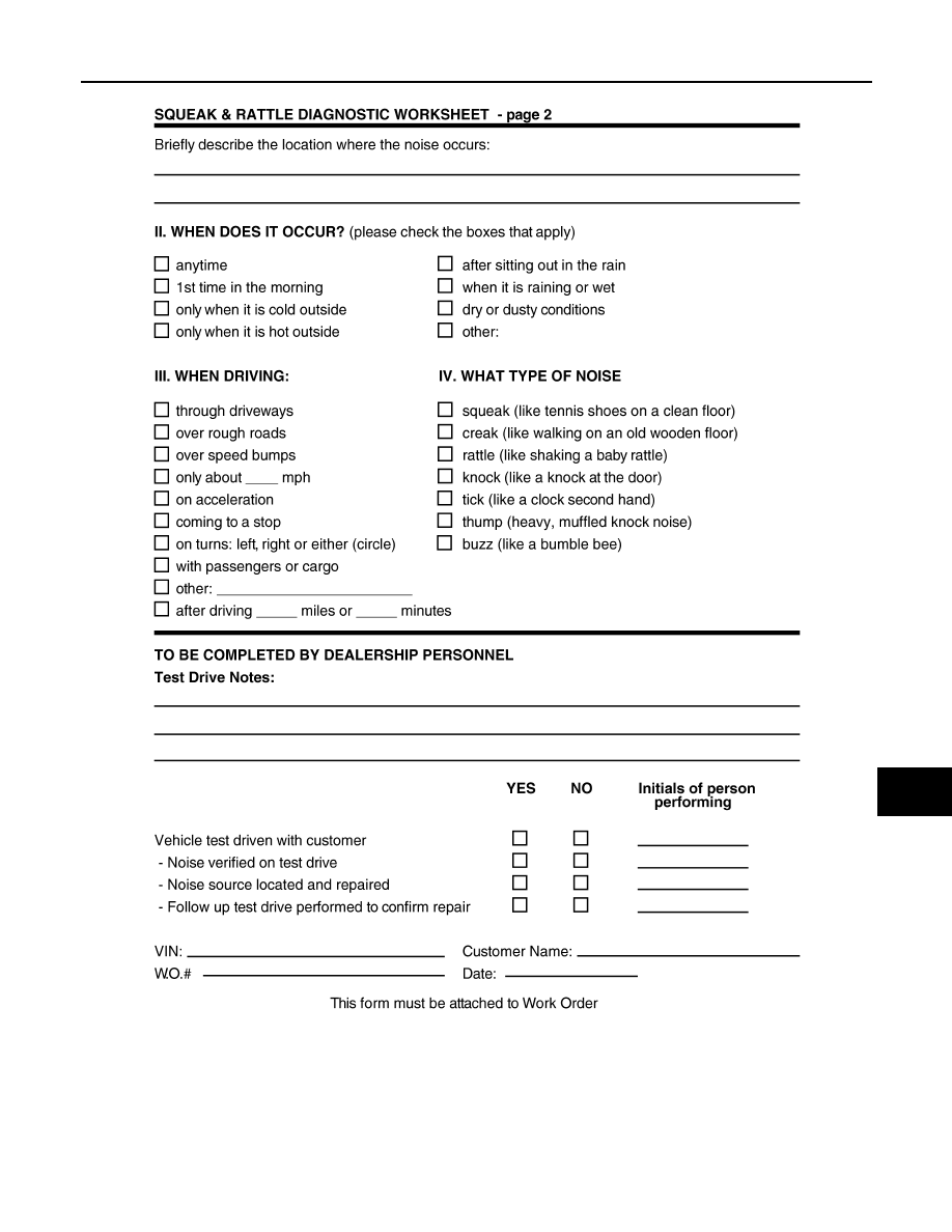
Diagnostic Worksheet
INFOID:0000000005187572
PIIB8740E
Revision: 2009 March
2009 Z12
SQUEAK AND RATTLE TROUBLE DIAGNOSES
MIR-11
< SYMPTOM DIAGNOSIS >
C
D
E
F
G
H
I
J
K
M
A
B
MIR
N
O
P
PIIB8742E
Revision: 2009 March
2009 Z12

MIR-12
< PRECAUTION >
PRECAUTIONS
PRECAUTION
PRECAUTIONS
Precaution for Supplemental Restraint System (SRS) "AIR BAG" and "SEAT BELT
PRE-TENSIONER"
INFOID:0000000005184000
The Supplemental Restraint System such as “AIR BAG” and “SEAT BELT PRE-TENSIONER”, used along
with a front seat belt, helps to reduce the risk or severity of injury to the driver and front passenger for certain
types of collision. This system includes seat belt switch inputs and dual stage front air bag modules. The SRS
system uses the seat belt switches to determine the front air bag deployment, and may only deploy one front
air bag, depending on the severity of a collision and whether the front occupants are belted or unbelted.
Information necessary to service the system safely is included in the “SRS AIR BAG” and “SEAT BELT” of this
Service Manual.
WARNING:
• To avoid rendering the SRS inoperative, which could increase the risk of personal injury or death in
the event of a collision which would result in air bag inflation, all maintenance must be performed by
an authorized NISSAN/INFINITI dealer.
• Improper maintenance, including incorrect removal and installation of the SRS, can lead to personal
injury caused by unintentional activation of the system. For removal of Spiral Cable and Air Bag
Module, see the “SRS AIR BAG”.
• Do not use electrical test equipment on any circuit related to the SRS unless instructed to in this
Service Manual. SRS wiring harnesses can be identified by yellow and/or orange harnesses or har-
ness connectors.
PRECAUTIONS WHEN USING POWER TOOLS (AIR OR ELECTRIC) AND HAMMERS
WARNING:
• When working near the Air Bag Diagnosis Sensor Unit or other Air Bag System sensors with the
ignition ON or engine running, DO NOT use air or electric power tools or strike near the sensor(s)
with a hammer. Heavy vibration could activate the sensor(s) and deploy the air bag(s), possibly
causing serious injury.
• When using air or electric power tools or hammers, always switch the ignition OFF, disconnect the
battery, and wait at least 3 minutes before performing any service.
Precaution Necessary for Steering Wheel Rotation after Battery Disconnect
INFOID:0000000005070071
NOTE:
• Before removing and installing any control units, first turn the push-button ignition switch to the LOCK posi-
tion, then disconnect both battery cables.
• After finishing work, confirm that all control unit connectors are connected properly, then re-connect both
battery cables.
• Always use CONSULT-III to perform self-diagnosis as a part of each function inspection after finishing work.
If a DTC is detected, perform trouble diagnosis according to self-diagnosis results.
This vehicle is equipped with a push-button ignition switch and a steering lock unit.
If the battery is disconnected or discharged, the steering wheel will lock and cannot be turned.
If turning the steering wheel is required with the battery disconnected or discharged, follow the procedure
below before starting the repair operation.
OPERATION PROCEDURE
1.
Connect both battery cables.
NOTE:
Supply power using jumper cables if battery is discharged.
2.
Turn the push-button ignition switch to ACC position.
(At this time, the steering lock will be released.)
3.
Disconnect both battery cables. The steering lock will remain released with both battery cables discon-
nected and the steering wheel can be turned.
4.
Perform the necessary repair operation.
Revision: 2009 March
2009 Z12

PRECAUTIONS
MIR-13
< PRECAUTION >
C
D
E
F
G
H
I
J
K
M
A
B
MIR
N
O
P
5.
When the repair work is completed, re-connect both battery cables. With the brake pedal released, turn
the push-button ignition switch from ACC position to ON position, then to LOCK position. (The steering
wheel will lock when the push-button ignition switch is turned to LOCK position.)
6.
Perform self-diagnosis check of all control units using CONSULT-III.
Revision: 2009 March
2009 Z12
MIR-14
< PREPARATION >
PREPARATION
PREPARATION
PREPARATION
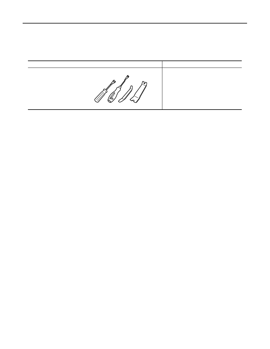
Commercial Service Tools
INFOID:0000000005070073
Tool name
Description
Remover tool
Removes the clips, pawls and metal clips
JMKIA3050ZZ
Revision: 2009 March
2009 Z12
INSIDE MIRROR
MIR-15
< REMOVAL AND INSTALLATION >
C
D
E
F
G
H
I
J
K
M
A
B
MIR
N
O
P
REMOVAL AND INSTALLATION
INSIDE MIRROR
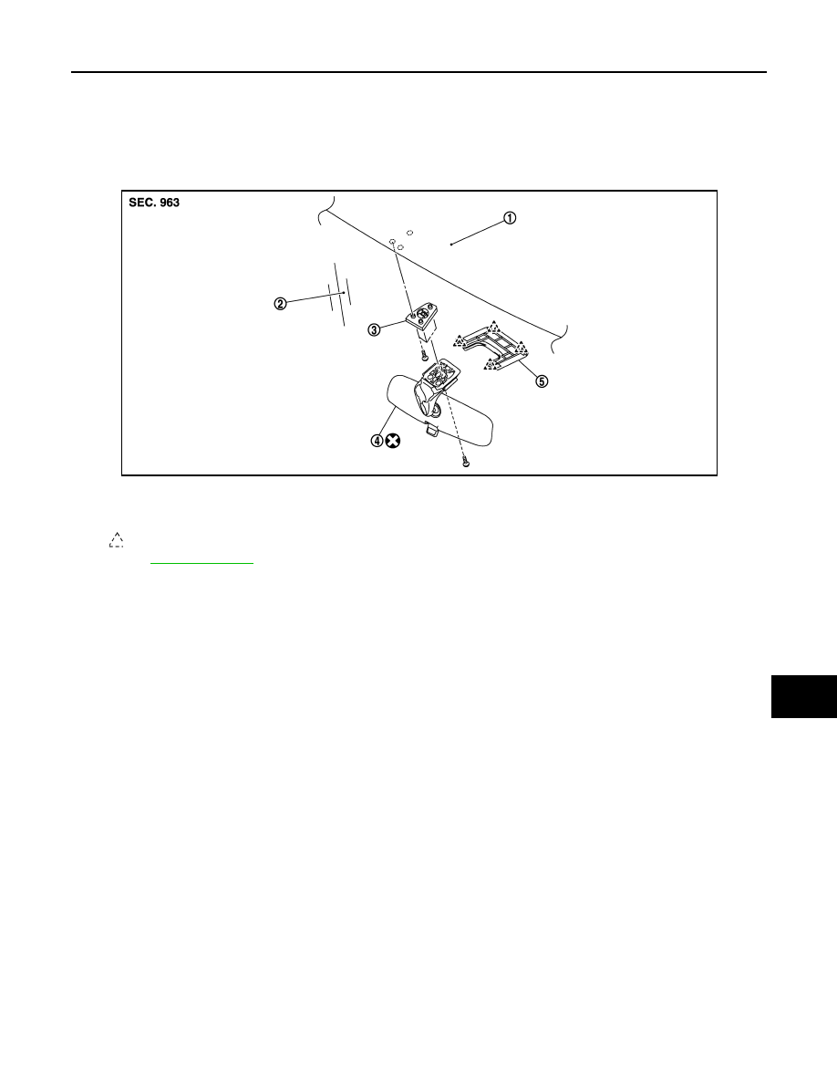
Exploded View
INFOID:0000000005070074
Removal and Installation
INFOID:0000000005070075
CAUTION:
Never reuse the inside mirror disassembled from mirror base.
REMOVAL
1.
Remove inside mirror cover.
2.
Disconnect harness connector from inside mirror.
3.
Remove inside mirror mounting bolt, and remove inside mirror.
4.
Remove mirror base mounting bolts, and remove mirror base.
INSTALLATION
Install in the reverse order of removal.
1.
Roof panel
2.
Windshield glass
3.
Mirror base
4.
Inside mirror
5.
Inside mirror cover
: Pawl
Refer to
for symbols in the figure.
JMLIA0326ZZ
Revision: 2009 March
2009 Z12
MIR-16
< REMOVAL AND INSTALLATION >
OUTSIDE MIRROR
OUTSIDE MIRROR
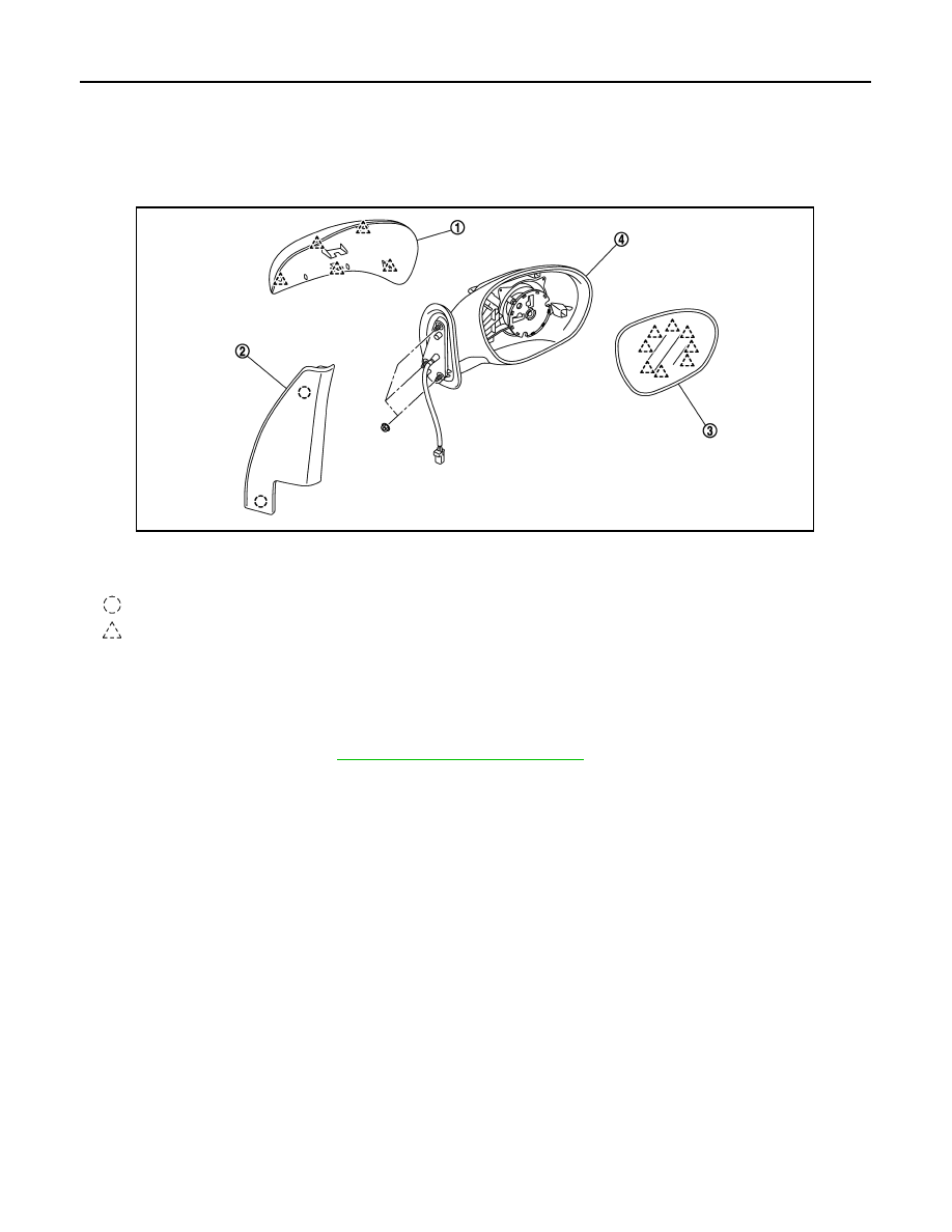
DOOR MIRROR ASSEMBLY
DOOR MIRROR ASSEMBLY : Exploded View
INFOID:0000000005070076
DOOR MIRROR ASSEMBLY : Removal and Installation
INFOID:0000000005070077
REMOVAL
1.
Remove door mirror corner cover.
2.
Remove door finisher. Refer to
INT-11, "Removal and Installation"
3.
Disconnect door mirror harness connector.
4.
Remove door mirror mounting nuts, and remove door mirror assembly.
INSTALLATION
Install in the reverse order of removal.
GLASS MIRROR
1.
Door mirror cover
2.
Door mirror corner cover
3.
Glass mirror
4.
Door mirror assembly
: Clip
: Pawl
JMLIA0328ZZ
Revision: 2009 March
2009 Z12
OUTSIDE MIRROR
MIR-17
< REMOVAL AND INSTALLATION >
C
D
E
F
G
H
I
J
K
M
A
B
MIR
N
O
P
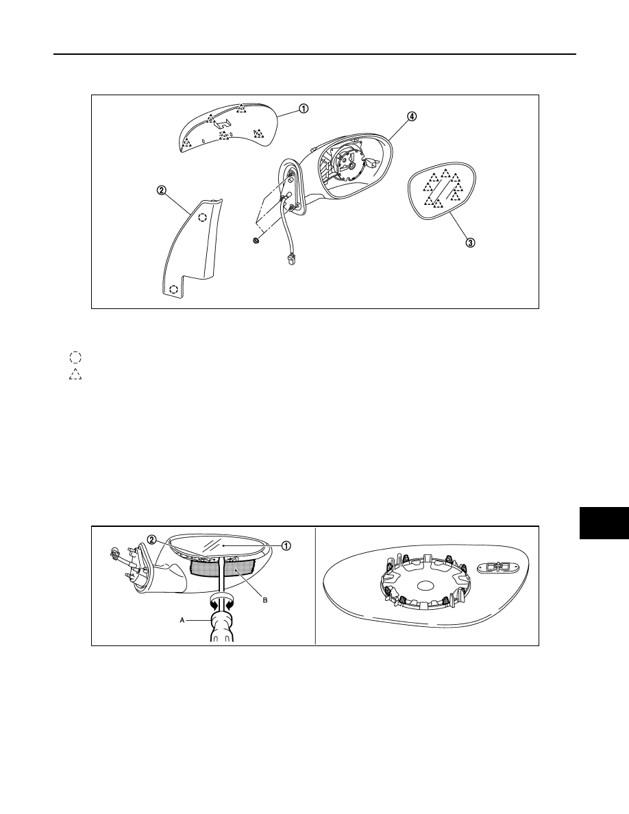
GLASS MIRROR : Exploded View
INFOID:0000000005070078
GLASS MIRROR : Disassembly and Assembly
INFOID:0000000005070079
DISASSEMBLY
1.
Place the glass mirror upward.
2.
Put a strip of protective tape (B) on housing assembly.
3.
Insert a small flat-bladed screwdriver (A) into the recess at lower side between glass mirror (1) and actua-
tor (2), and push up pawls to remove glass mirror lower side.
NOTE:
Insert a small flat-bladed screwdriver into recesses, and push up while rotating (twisting) to make work
easier.
4.
Insert a small flat-bladed screwdriver at LH/RH side between glass mirror and actuator, and push up
pawls to remove glass mirror LH/RH side.
NOTE:
Insert a small flat-bladed screwdriver into recesses, and push up while rotating (twisting) to make work
easier.
ASSEMBLY
Assemble in the reverse order of disassembly.
CAUTION:
After installation, visually check that pawls are securely engaged.
DOOR MIRROR COVER
1.
Door mirror cover
2.
Door mirror corner cover
3.
Glass mirror
4.
Door mirror assembly
: Clip
: Pawl
JMLIA0328ZZ
JMLIA0327ZZ
Revision: 2009 March
2009 Z12
MIR-18
< REMOVAL AND INSTALLATION >
OUTSIDE MIRROR
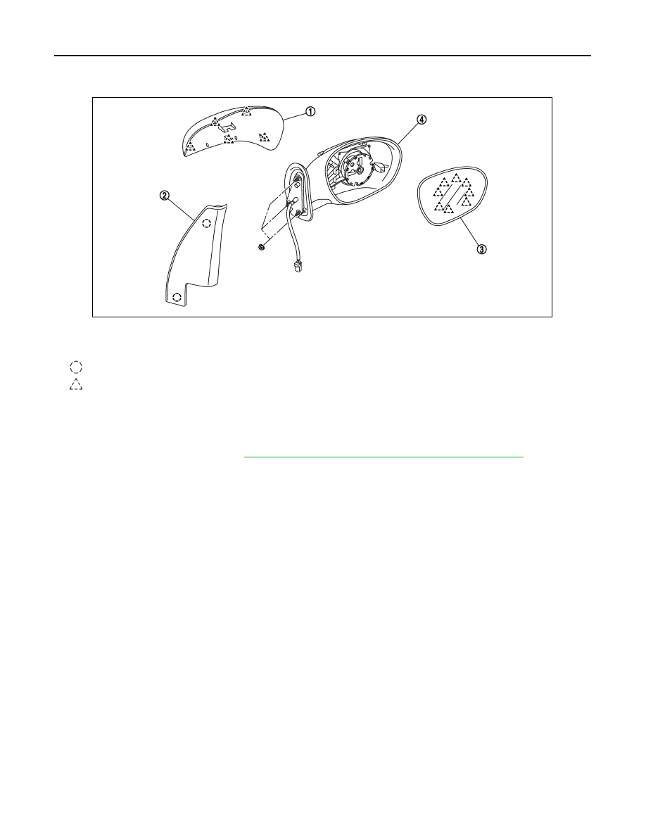
DOOR MIRROR COVER : Exploded View
INFOID:0000000005070080
DOOR MIRROR COVER : Disassembly and Assembly
INFOID:0000000005070081
DISASSEMBLY
1.
Remove the glass mirror. Refer to
MIR-17, "GLASS MIRROR : Disassembly and Assembly"
2.
Remove the pawls, and disassemble the door mirror cover from the mirror assembly.
ASSEMBLY
Assemble in the reverse order of disassembly.
CAUTION:
After installation, visually check that pawls are securely engaged.
1.
Door mirror cover
2.
Door mirror corner cover
3.
Glass mirror
4.
Door mirror assembly
: Clip
: Pawl
JMLIA0328ZZ
Revision: 2009 March
2009 Z12

DOOR MIRROR REMOTE CONTROL SWITCH
MIR-19
< REMOVAL AND INSTALLATION >
C
D
E
F
G
H
I
J
K
M
A
B
MIR
N
O
P
DOOR MIRROR REMOTE CONTROL SWITCH
Exploded View
INFOID:0000000005092294
Removal and Installation
INFOID:0000000005092295
REMOVAL
1.
Remove the power window main switch finisher.
2.
Remove door mirror remote control switch from power window main switch finisher using flat-bladed
screwdriver.
INSTALLATION
Install in the reverse order of removal.
Revision: 2009 March
2009 Z12
Document Outline
- QUICK REFERENCE INDEX
- Table of Contents
- DTC/CIRCUIT DIAGNOSIS
- SYMPTOM DIAGNOSIS
- PRECAUTION
- PREPARATION
- REMOVAL AND INSTALLATION
- POWER SUPPLY ROUTING CIRCUIT
- FUSE BLOCK - JUNCTION BOX (J/B)
- FUSE, FUSIBLE LINK AND RELAY BOX
Wyszukiwarka
Podobne podstrony:
Ziba Mir Hosseini Towards Gender Equality, Muslim Family Laws and the Sharia
rossijskoe oruzhie vojna i mir
vonnno polevoj obman v chechne nastupil mir konca kotoromu ne
zaterjannyj mir ili maloizvestnye stranicy belorusskoj istorii
Lilli Wolfram machs mir atemlos
Przekład pomocnika Math-o-Mir 1.71, Opisy programów FREE
Maksi Guderian Mir v voynah 422358
Bathen Etot dobryy zhestokiy mir sbornik 394910
Skryagin00 katastrof kotoryie potryasli mir 168023
Solovev Ogrableniya kotoryie potryasli mir Zahvatyivayuschie istorii o vyidayuschihsya kriminalnyih
Etkind Mir mog byt drugim Uilyam Bullit v popytkah izmenit HH vek 403172
4 Ekonomika MiR id 37568 Nieznany
Credit MIR article
wzor strony tytulowej sprawozdania PA AiR, Studia ATH AIR stacjonarne, Rok III specjalność MiR - SM,
Bachtin M Odpowiedź na pytanie redakcji Nowyj Mir
bei mir bistu shein pfte cl vni vla vc vox
Leyn Arabskiy mir v epohu Tyisyachi i odnoy nochi 192191
Ulanov Naydennyy mir 269273
więcej podobnych podstron