
Table of Contents
SAFETY PRECAUTIONS AND WARNINGS .............................................. 1
USING THE TEST TOOL .............................................................................. 2
...................................................................................... 2
............................................................................................ 3
............................................................................... 3
................................................................................ 4
......................................................................................... 4
........................................................................................ 6
................................................................................................. 6
.................................................................. 9
................................................................................... 9
.......................................................................... 11
............................................... 12
.......................................... 13
............................................. 14
..................................................... 15
.................................................. 16
.............................................. 17
LED ...................................................................... 18
TEST TOOL SPECIFICATIONS................................................................. 19
TEST TOOL KNOW-HOW .......................................................................... 20
WARRANTY AND SERVICE ...................................................................... 22
................................................................ 22
................................................................................ 22

1
1. Safety Precautions and Warnings
To prevent personal injury or damage to vehicles and/or the test
tool, read this instruction manual first and observe the following
safety precautions at a minimum whenever working on a vehicle:
Always perform automotive testing in a safe environment.
Wear safety eye protection that meets ANSI standards.
Keep clothing, hair, hands, tools, test equipment, etc. away from
all moving or hot engine parts.
Operate the vehicle in a well ventilated work area: Exhaust gases
are poisonous.
Put blocks in front of the drive wheels and never leave the vehicle
unattended while running tests.
Use extreme caution when working around the ignition coil,
distributor cap, ignition wires and spark plugs. These
components create hazardous voltages when the engine is
running.
Put the transmission in PARK (for automatic transmission) or
NEUTRAL (for manual transmission) and make sure the parking
brake is engaged.
Keep a fire extinguisher suitable for gasoline/chemical/ electrical
fires nearby.
Don‟t connect or disconnect any test equipment while the
ignition is on or the engine is running.
Keep the tool dry, clean, free from oil/water or grease. Use a mild
detergent on a clean cloth to clean the outside of the test tool,
when necessary.
When the power switch in the tool is depressed battery
current/voltage is conducted directly to the tip which may cause
sparks when contacting ground or certain circuits. Therefore the
tool should NOT be used around flammables such as gasoline or
its vapors. The spark of an energized tool could ignite these
vapors. Use the same caution as you would when using an arc
welder.
2
2. Using the Test Tool
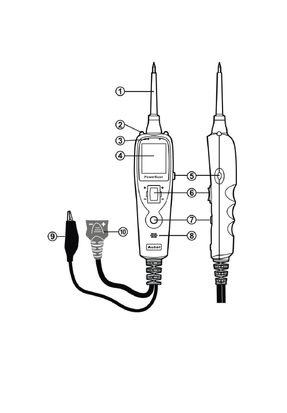
2.1 Tool Description
① Probe Tip – Contacts the circuit or component to be tested.
② Head Lights – Illuminates dark work areas or work areas at
night. .
③ Red/Green Polarity Indicator – Identifies positive, negative or
open circuits. The RED Indicator lights when the Probe Tip is

3
contacting a positive circuit. The GREEN Indicator lights when
the Probe Tip is contacting a negative circuit.
④ LCD Display –Indicates test results.
⑤ Circuit Breaker Reset – Resets the tool when the Circuit
Breaker is tripped。
⑥ Power Switch – Allows you to conduct a positive or negative
battery current to the tip for activating and testing the function
of electrical components.
⑦ Mode Button – Selects the work mode: AC voltage, DC
voltage, resistance, tone.
⑧ Speaker – When the audio tone is turned on, a beep will be
heard.
⑨ Auxiliary Ground Lead – Assists test as a ground lead.
⑩ Adaptor – Connects to the battery.
2.2 Specifications
1) Display: TFT color display (160 x 128 dpi)
2) Operating Temperature: 0 to 60°C (32 to 140 F°)
3) Storage Temperature: -40 to 70°C (-40 to 185 F°)
4) External Power: 12.0 or 24.0 V power provided via vehicle
battery
5) Dimensions:
Length Width Height
126 mm (4.96”) 46.5 mm (1.83”) 35 mm (1.38”)
6)
NW: 0.105kg (0.23lb), GW: 0.726 kg(1.6lb)
2.3 Accessories Included
1) User‟s Manual.
2) Cigarette lighter adapter.
3) Battery hookup clips
4) Probe tip.
5) 20ft. extension cable.

4
6) Rugged blow molded case.
2.4 General Description
The tool is the best electrical tester for reducing diagnostic time in all
6- to 30-volt vehicle electrical systems. After a simple hook-up of the
tool to the vehicle's battery, you can:
determine at a glance if a circuit is positive, negative, or open
without having to reconnect clips from one battery pole to
another.
test for continuity with its built-in auxiliary ground lead.
by depressing the power switch, conduct a positive or negative
battery current to the probe tip for testing the function of an
electrical component without the use of jumper wires.
test for poor ground contacts instantly without performing
voltage drop tests. The tool is also short-circuit protected; its
internal circuit breaker will trip if it becomes overloaded.
follow and locate short circuits without wasting fuses. The tool's
long cable allows you to test along the entire length of the
vehicle without constantly searching for suitable vehicle
grounds.
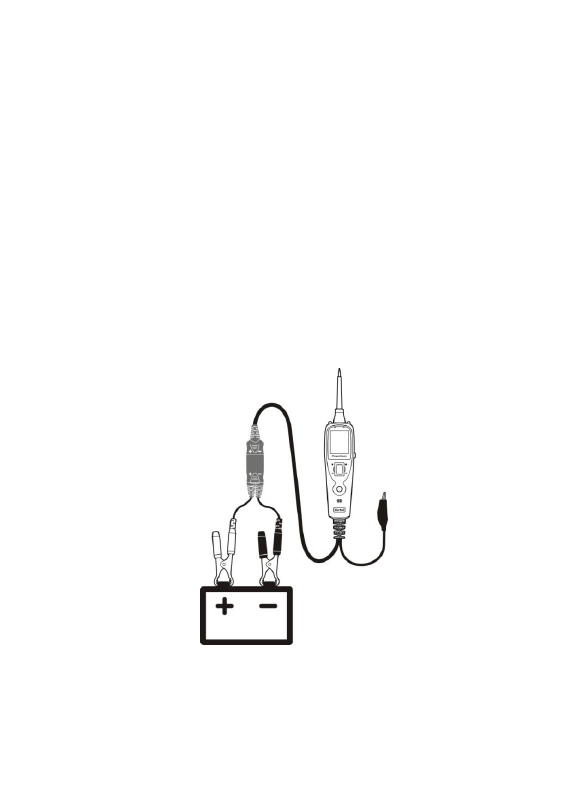
2.5 Power
The tool is powered via the vehicle battery. Connect the RED battery
clamp to the POSITIVE terminal of the vehicle‟s battery, and the
BLACK clamp to the NEGATIVE terminal. When the tool is first
connected to a battery (power source), it will sound a beep and the
Head Lights will be on to illuminate the test area of the probe tip.
2.6 Quick Self-Test
Before you test a circuit or component, be sure your tool is in good
order by doing a quick self-test.
5
With the tool connected, perform a quick self-test. The power switch
is a momentary rocker switch located on the tool's body. Flanking the
switch are positive and negative markings.
Press the Power Switch forward to activate the tip with a positive
voltage. The Red LED should light and the LCD display will read
the battery voltage. If the tone feature is turned on, a high pitched
tone will sound. Let go of the power switch and the LED will turn
off and the high tone will cease.
Press the Power Switch rearward to activate the tip with a negative
voltage. The Green LED should light and the LCD display will read
the „0.0V‟ (ground). If the tone feature is turned on, a low pitched
tone will sound. Let go of the power switch and the LED will turn
off and the low tone will cease.
Your tool is working correctly and is now ready for use. (Figure 1)
Figure 1
IMPORTANT: When powering-up components, you can increase
the life of power switch in the tool if you first press the switch, then
6
contact the tip to the component. The arcing will take place at the tip
instead of the contacts of the switch.
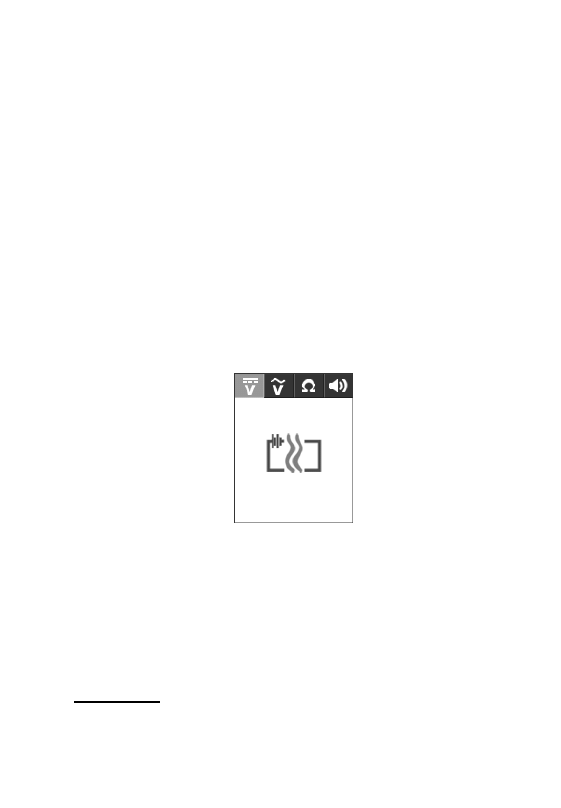
2.7 Circuit Breaker
The tool is short-circuit protected. Its internal circuit breaker will trip
if it becomes overloaded. The circuit breaker is a valuable test tool as
well as a safety measure to protect the tool from overload.
When circuit breaker tripped, the LCD will display as below. (Figure
2) All other functions of the tool are still active, which means you
can still probe a circuit and observe the voltage reading. When the
circuit breaker is tripped, the tool will NOT be able to conduct
battery current to the tip even when the power switch is pressed.
Intentionally tripping the breaker and using the tool to probe can be
considered an added precaution against accidental pressing of the
power switch.
Figure 2
2.8 Work mode
There are four modes to diagnose the electrical systems, which can
be accessed by depressing the Mode Button and cycling through each
one.
DC voltage
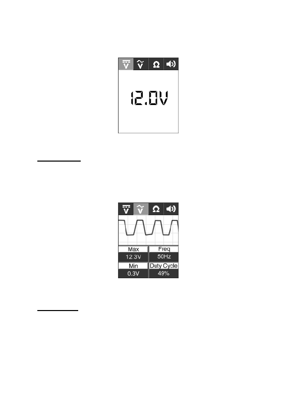
7
While the tool in this mode, contact the probe tip to a circuit, then the
LCD display will read the DC voltage with a resolution of 0.1 volt.
(Figure 3)
Figure 3
AC voltage
While the tool in this mode, contact the probe tip to a circuit, then the
LCD display will read the Max. voltage, the Min. voltage, frequency
and duty cycle. ( Figure 4).
Figure 4
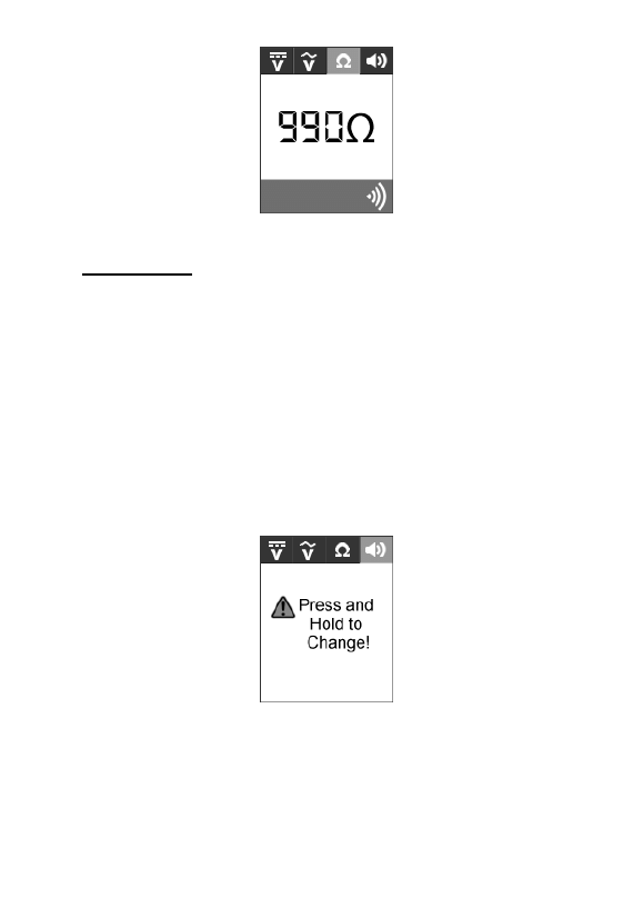
Resistance
While the tool in this mode, contact the probe tip to a circuit, then the
LCD display will read the resistance between the tip and auxiliary
ground lead. (Figure 5)
8
Figure 5
Tone On/Off
While the tool in this mode, just do a quick press of the mode button
to toggle the tone on or off. While quickly pressing (a quick press
and release) the mode button, if a short high beep is heard, this
means the audio tone is turned on. If a short low beep is heard, the
audio tone is turned off. (Figure 6)
This function is invaluable when working in bright areas where LED
illumination alone is not sufficient. The audio feature may be
disengaged when desired, such as for applications where the tool will
be connected to circuits for long periods of time and the audio could
become annoying.
Figure 6
9
3. Test Applications
3.1 Voltage & Polarity Testing
While the tool is in DC Voltage mode, contact the probe tip to a
POSITIVE circuit. The red LED will light and the LCD displays the
voltage with a resolution of 0.1V. If the beep is turned on, a high
pitched tone will sound.
If contact the probe tip to a NEGATIVE circuit, the green LED will
light and the LCD displays the voltage with a resolution of 0.1V. If
the beep is turned on, a low pitched tone will sound.
If contact the probe tip to an OPEN circuit, neither of the LED will
light.(Figure 7)
Figure 7
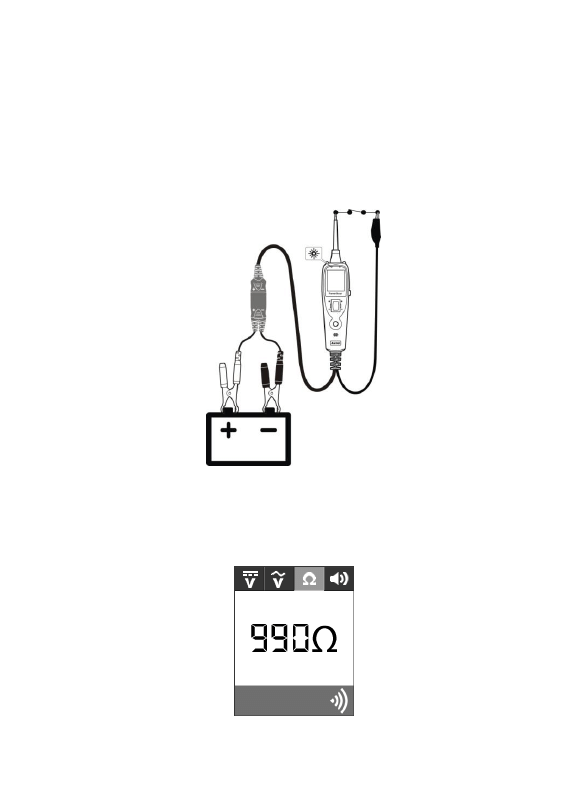
3.2 Continuity Testing
10
While the tool is in Resistance mode, using the probe tip with chassis
ground or the auxiliary ground lead, continuity can be tested on wires
and components attached or disconnected from the vehicle‟s
electrical system.
When the probe tip is contacting a good ground, the LCD will
indicate “0.0Ω ” and green LED will be on. If the tone feature is
turned on, a low pitched tone will sound.(Figure 8)
Figure 8
In other cases, the LCD only indicates the resistance value.
(Figure 9)
Figure 9

11
If the resistance value is greater than 200kΩ , the LCD will
show “0L”.
There is also another way to prove continuity of connections to
ground or battery. Power up the connection using the power switch.
If the circuit breaker trips you know that you have a good solid low
resistance connection.
NOTE: You can use the probe tip to pierce the plastic insulation on
a wire. This means that you can test the circuit without
disconnecting anything.
3.3 Signal Circuit Testing
Once you extract a DTC from the vehicle and realize that
troubleshooting begins with some kind of sensor circuit, there is a
quick test you can perform to verify the code. Testing your sensor is
easy while using the tool.
For example, you suspect there is a problem with your M.A.P. sensor
circuit, then follow the procedure involved with testing this sensor:
Set the tool in AC Voltage mode, using the probe tip with
chassis ground or the auxiliary ground lead.
Connect vacuum pump to MAP sensor.
Contact the probe tip to the MAP sensor positive terminal and
observe the LCD readings which should be a sine wave in
normal condition.
Apply vacuum.
Release vacuum and observe the LCD readings.(Figure 10)

12
Figure 10
If the LCD readings are abnormal, there is a problem with this
sensor.
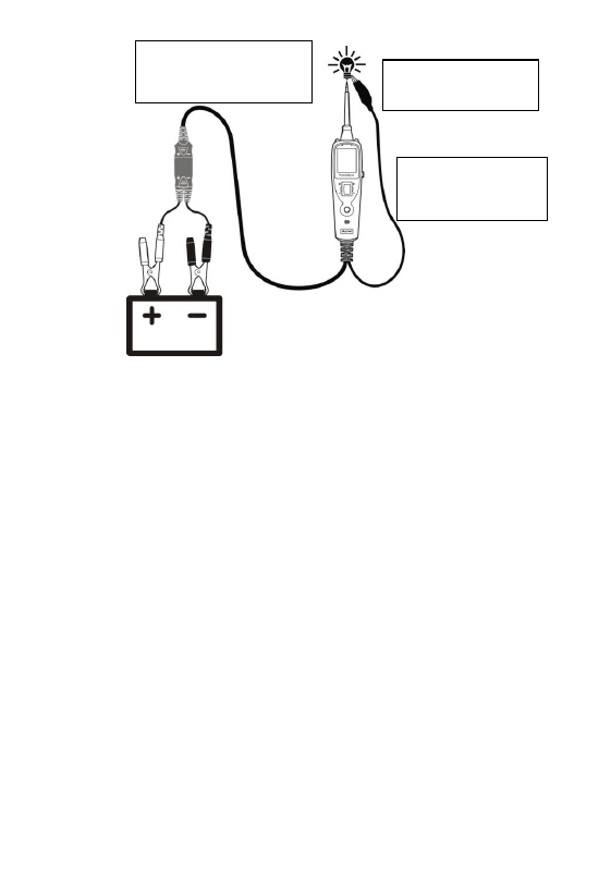
3.4 Activating Components in Your Hand
While the tool is in DC Voltage mode, by using the probe tip in
connection with the auxiliary ground lead, components can be
activated right in your hand, thereby testing their functions.
Connect the auxiliary ground lead to the negative terminal or ground
side of the component being tested. Then contact the probe tip to the
positive terminal of the component, the green LED should light,
indicating continuity through the component.
While keeping an eye on the green LED, quickly press and release
the power switch forward. If the green LED went out and the red
LED came on, you may proceed with further activation. Rock the
power switch forward and hold it down to provide power to your
component. With the power switch rocked forward, power will flow
from the positive lead on the battery into the probe tip, through the
tip into the component‟s positive terminal, into the component and
out of the component, through the auxiliary ground lead and back
into the tool, and back to the vehicle‟s battery‟s ground. (Figure 11)
13
Figure 11
If the green LED went off at that instant or if the circuit breaker
tripped, the tool has been overloaded. This could happen for the
following reasons:
The contact you are probing is a direct ground or negative
voltage.
The component you are testing is short-circuited.
The component is a very high current component (i.e., starter
motor).
If the circuit breaker is tripped, reset it by waiting for it to cool down
(15 sec.) and then depressing the reset button.
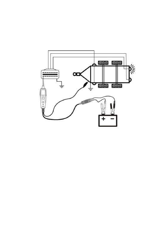
3.5 Testing Trailer Lights and Connections
While the tool in DC Voltage mode, clip the auxiliary ground lead to
the trailer ground, probe the contacts at the jack and then apply
Contact the tip to the
positive terminal of the
bulb
Connect the negative
auxiliary clip
Press
the
power
switch forward to
activate the bulb
14
voltage to the probe tip. This lets you check the function and
orientation of the connector and trailer lights. (Figure 12)
If the circuit breaker tripped, that contact is likely a ground. Reset the
circuit breaker by letting it cool down for 15 seconds and depressing
the reset button until it clicks into place.
Figure 12
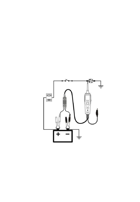
3.6 Activating Components in The Vehicle
While the tool in DC Voltage mode, contact the probe tip to the
positive terminal of the component, the green LED should light,
indicating continuity to ground. While observing the green LED,
quickly depress and release the power switch forward. If the green
LED went out and the red LED came on, you may proceed with
further activation. (Figure 13) If the green LED went off at that
instant or if the circuit breaker tripped, the tool has been overloaded.
This could happen for the following reasons:
The contact you are probing is a direct ground.
The component you are testing is short-circuited.
15
The component is a very high current component(i.e., starter
motor).
If the circuit breaker is tripped, reset it by waiting for it to cool down
(15 sec.) and then depressing the reset button.
WARNING : Haphazardly applying voltage to certain circuits can
cause damage to a vehicle’s electronic components. Therefore, it is
strongly advised to use the vehicle manufacturer’s schematic and
diagnosing procedure while testing.
NOTE : When powering up components, you can increase the life
of power switch if you first press the switch, then contact the tip to
the component. The arcing will take place at the tip instead of the
contacts of the switch.
Figure 13
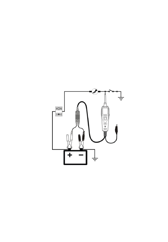
3.7 Activating Components w/Ground
While the tool in DC Voltage mode, contact the probe tip to the
negative terminal of the component, the red LED should light. While
observing the red LED, quickly depress and release the power switch
rearward. If the red LED went out and the green LED came on, you
16
may proceed with further activation. (Figure 14) If the green LED
went off at that instant or if the circuit breaker tripped, the tool has
been overloaded. This could happen for the following reasons:
The contact you are probing is a direct positive voltage.
The component you are testing is short-circuited.
The component is a very high current component(i.e., starter
motor).
If the circuit breaker is tripped, reset it by waiting for it to cool down
(15 sec.) and then depressing the reset button.
Figure 14
WARNING : With this function, if you are contacting a protected
circuit, a vehicle’s fuse can be blown or tripped if you apply ground
to it.
3.8 Checking for Bad Ground Contacts
Probe the suspected ground wire or contact with the probe tip.

17
Observe the green LED. Depress the power switch forward then
release. If the green LED went out and the red LED came on, this is
not a true ground..
If the circuit breaker tripped, this circuit is more than likely a good
ground. Keep in mind that high current components such as starter
motors will also trip the circuit breaker.
3.9 Following & Locating Short Circuits
In most cases a short circuit will appear by a fuse or a fusible link
blowing or an electrical protection device tripping (i.e., a circuit
breaker). This is the best place to begin the search.
Remove the blown fuse from the fuse box.
Use the probe tip to activate and energize each of the fuse
contacts. The contact which trips the circuit breaker is the
shorted circuit. Take note of this wire‟s identification code or
color.
Follow the wire as far as you can along the wiring harness.
Here is an example for this application.
If you are following a short in the brake light circuit, you may
know that the wire must pass through the wiring harness at the
door sill. Locate the color-coded wire in the harness and expose
it.
Probe through the insulation with the probe tip, and depress the
power switch forward to activate and energize the wire.
If the circuit breaker tripped, you have verified the shorted wire.
Cut the wire and energize each end with the probe tip. The wire
end which trips the circuit breaker again is the shorted circuit
and it will lead you to the shorted area.

18
Follow the wire in the shorted direction and repeat this process
until the short is located.
3.10 Red/Green Polarity LED
The Red/Green Polarity LED lights up when the probe tip voltage
matches the battery voltage within ±0.8 volts. It is added information
that could be valuable to the technician.
If the circuit you are testing is not within a 0.8 volt (plus or minus) of
supply voltage, you will see the voltage reading on the LCD but you
will not hear a tone or see a red or green LED. This tells you either
you have a voltage drop in excess of 0.8 volt from battery voltage or
you are probing a circuit that has an increase of a 0.8 volt or more
over battery voltage.
To determine battery voltage, simply remove the tip from the circuit
and press the power switch forward. Battery voltage will then be
displayed on the LCD. The difference between the battery voltage
and what is read on the circuit is either voltage drop or voltage
increase. This allows you to determine a voltage drop without
running back to check the battery. It‟s just another one of time saving
feature the tool has.
19
4. Test Tool Specifications
DC voltage range : 0-65V +1 digit
Resistance range : 0 – 200 KΩ
Frequency response of tone pass through
0Hz to 10Khz.
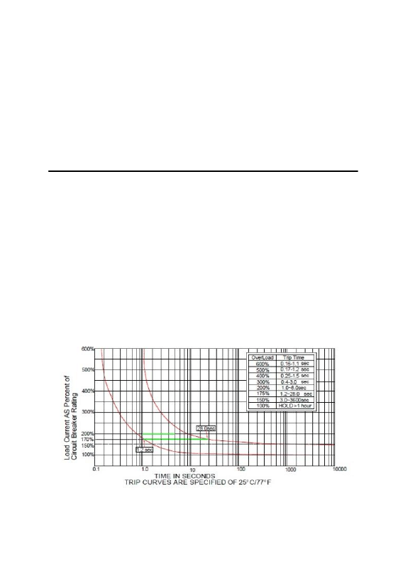
Circuit Breaker
Rating current: 1 – 10 Amp
Testing Standard
100% current : no trip
150% current: trip in one hour
200% current: trip in 3-30 seconds.
300% current: trip in 0.5-4.0 seconds.

20
5. Test Tool Know-how
1) Is the PowerScan Probe Tester computer and air bag safe?
The tool LED and LCD pull no more than 1 milliamp of current,
therefore when using it as a test light or multimeter it is computer
and airbag safe. However, pressing the power switch is a different
story. When you press the switch forward, you are conducting full
battery current to the tip of the probe. There is a nice safety feature
built into the tool. Simply connect the extra ground lead to the tool
and press the power switch forward until it trips the circuit breaker.
This will prevent power from going to the tip but still allow you to
use the tool as a multimeter. When you are away from computer
components, simple press the reset button and you are ready to
power up again.
2) Why do I have no power at the tip when I am pressing the power
switch forward but the red LED is on?
The power switch goes through a lot. It is one of the few things that
go wrong with the tool. The switch is a consumable that needs to be
replaced on occasion. We have made it real simple to not only
change it but also buy a new switch. The switch can be snapped out
and replaced in seconds.
You can buy switches from your Autel authorized tool supplier.
The tool with the Rocker Switch slots makes it easy to replace a
worn switch in the field without having to send it in for repair.
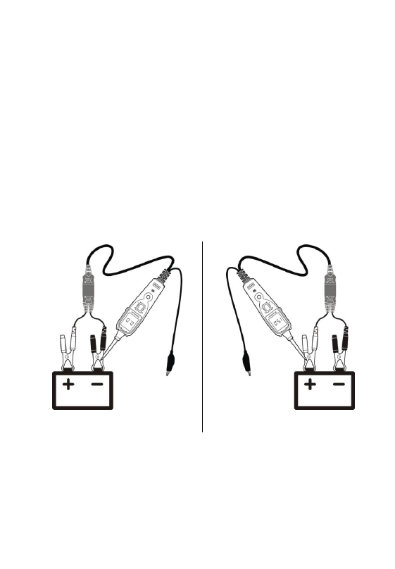
Power Switch replacement procedure:
Remove the worn switch with a pry tool. Be careful when
applying force. (Figure 15)
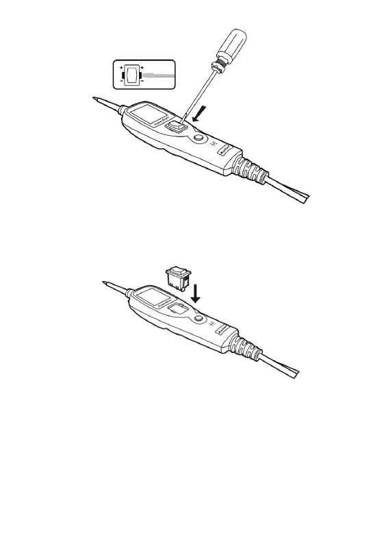
21
Figure 15
Make sure to install the switch straight and press until flush with
casing. (Figure 16)
Figure 16
It is recommended when buying you get two. This will fix your tool
now and give you a spare so you won‟t experience any down time in
the future.

22
6. Warranty and Service
6.1 Limited One Year Warranty
Autel warrants to its customers that this product will be free from all
defects in materials and workmanship for a period of one (1) year from
the date of the original purchase, subject to the following terms and
conditions:
1) The sole responsibility of Autel under the Warranty is limited to
either the repair or, at the option of Autel, replacement of the test
tool at no charge with Proof of Purchase. The sales receipt may be
used for this purpose.
2) This warranty does not apply to damages caused by improper use,
accident, flood, lightning, or if the product was altered or repaired
by anyone other than the Manufacturer‟s Service Center.
3) Autel shall not be liable for any incidental or consequential
damages arising from the use, misuse, or mounting of the test tool.
Some states do not allow limitations on how long an implied
warranty lasts, so the above limitations may not apply to you.
4) All information in this manual is based on the latest information
available at the time of publication and no warranty can be made
for its accuracy or completeness. Autel reserves the right to make
changes at any time without notice.
6.2 Service Procedures
If you have any questions, please contact your local store, distributor
or visit our website at www.auteltech.com.
If it becomes necessary to return the test tool for repair, contact your
local distributor for more information.
Wyszukiwarka
Podobne podstrony:
cas test platform user manual
CARPROG Opel ECU programmer user manual
elm327 interface viecar obd2 bluetooth scanner user manual
Chartplanner user manual
INPA User manual
all100 user manual
CARPROG user manual
FX2N 485 BD User's Manual JY992 Nieznany
mb sbc tool user manual
07 Altistart48 user manual
iphone user manual pdf
PRDM 0010 Upgrade user manual UPG 0001
TK105 GPS Tracker User Manual
ATDSK1118 User Manual
FX2N 232 IF User's Manual JY992D66701
Protek 3502C USER MANUAL
Administrator User Manual
więcej podobnych podstron