
PIPING DRAWINGS BASICS
N.P.TODKAR

There are two types of views used in the piping drawings:
a) Orthographic- Plans and Elevations
b) Pictorial - Isometric Views
Piping layout is developed in both plan view and elevation view
and section details are added for clarity wherever necessary.
These drawings are called the General Arrangement of Piping.
In complex piping system, especially within the unit/plant building
where orthographic views do not illustrate the details of design,
pictorial view in isometric presentation is drawn for clarity.

The Indian Standard IS10711 standardises the
drawing sheets as below:
SIZE OVERALL
DIMENSIONS in mm
A0
-
841 x 1189
A1
-
594 x 841
A2
-
420 x 594
A3
-
297 x 420
A4
-
210 x 297

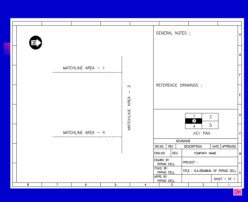
HOW TO START THE PIPING GA?
•
Obtain the drawings numbers and fill in the title block, with the
drawing number and title at the bottom right hand corner of the
sheet.
•
Place the north arrow at the top left/right hand corner of the
sheet to indicate plant north.
•
Do not plan drawing in the area above the title block of
drawing, as this is allotted for general notes, number and title of
reference drawings, brief description of changes during revision
and the bill of materials wherever applicable.
•
Process equipment and piping have priority on the Piping GA.
•
The piping drawings are started after fixing positions of the
equipments.
•
Equipment layout is reproduced on the Piping GA to its scale
and drawn on the reverse side in case of manual drafting.
•

•
In case of CAD separate layer is used. The major primary
beams and secondary beams are also shown if area covered is
indoor.
•
Pertinent background details which govern piping routing,
such as floor drains, HVAC ducting, electrical and instrument
cable trays, etc. are also drawn in faint on the reverse.
•
Utility stations are also established so that most convenient
utility header routing can be carried out.

Order of importance/preference of pipe lines in a piping
GA
1.
Alloy steel/special material of construction.
2.
Large bore piping
3.
High temp/high pr. Piping
4.
Lined piping
5.
C. S. Process Piping
6.
Utility piping

DEVELOPMENT OF PIPING GENERAL
ARRANGEMENT DRAWING
•
The piping drawings should be developed in such a way
that
all the process requirements are met with.
•
It is not always possible for the piping drawing to follow
exactly the logical arrangement of the P & IDs. Sometimes
lines must be routed with different junction sequence and
line numbers and subsequently the list may be changed.
•
Performance and economics have to be considered in
parallel while deciding the routing.
•
Piping is represented by single lines up to a size of 150NB
and double lines for sizes 200NB and above. This is to save
the time of drafting and to avoid confusion.
•
In single line representation only the center line of the
pipeline is drawn using solid line and in double line
representation the actual size to scale is drawn with center
line marked in chain-dotted lines

•
Line numbers are shown against each line exactly in the
same way as represented in the P&I diagrams.
•
The change in specification should be shown in line with
P&I diagram. This change is usually indicated
immediately to the downstream of the valve, flange or
equipment.
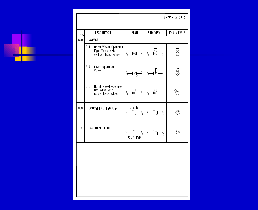
•
Valves should be drawn to scale with identification
number from the P&ID marked thereon.
•
Draw valve hand wheels to scale with stem fully
extended.
If it is lever operated, then the movement of handle
position should be marked.
•
If a valve is chain operated, note the distance of the chain
from the operating floor.
•
Show location of each instrument connection with
encircled instrument number taken from P&ID.
•
Similar arrangement shall be shown as typical detail or
covered in a separate company standard as Instrument
Hook-up drawings.

•
Draw plan view of each floor of the plant and these views
should indicate how the layout will look like between
floors as seen from top.
•
Each line should be identified by line number and should
also show the insulation, tracing requirements, etc.
•
Lines, if required, shall be broken to show the required
details of hidden lines without drawing other views.
•
Do not draw details that can be covered by a note.
•
Draw plan to a larger scale for any part needing more
details and identify it as “Detail ‘A’”, etc.
•
Draw part isometrics sketches or part elevations to clarify
complex piping or piping hidden in the plan view.
•
Full sections through the plant may be avoided if
isometric drawings are drawn for the lines. Part sections
where required shall be shown to clear the hidden details in
plan.
•
Sections in the plan views are identified by numbers say
1-1, 2-2, etc. and details by alphabets, e.g. “Detail ‘A’”.
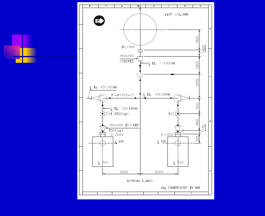
FIG.2: TYPICAL GENERAL ARRANGEMENT OF PIPING
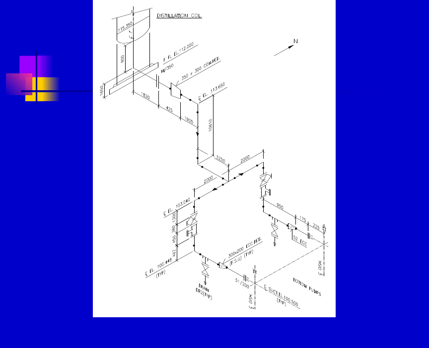
FIG.3: TYPICAL PIPING ISOMETRIC DRAWING

•
Isometric drawing should also include the following
information:
•
Dimensions and angles.
•
Reference number of P & IDs, GA Drawings, line
numbers, direction of flow, insulation and tracing.
•
Equipment location and equipment identification.
•
Give nozzle identification on the connected equipment.
•
Give the details of flange on the equipment if the
specification is different from the connecting piping.
•
Size and type of every valve/ Direction of operation.
•
Size and number of control valve.
•
Location, orientation and number of each equipment.
•
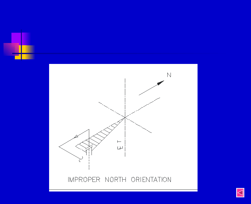
Plant North - The direction should be so selected as to
facilitate easy checking of GA with Iso

•
Field weld - preferred in all directions to take care of site
variations. Can also be covered with a general note.
•
Location of high point vents and low point drains.
Covered with a standard arrangement note.
•
Bill of Material.
•
Requirements of stress relieving, seal welding, pickling,
coating, etc.


SPOOLS
A spool is an assembly of fittings, flanges and pipes that
may be prefabricated. It does not include bolts, gaskets,
valves or instruments. A spool sheet is an orthographic
drawing of a spool drawn either from piping GA or from
an iso sheet. Each spool sheet shows only one type of
spool and,
•Instructs welder to fabricate the spool
•Lists the cut lengths of pipe, fittings and flanges etc.
needed to make the spool
•Gives material of construction and any special treatment
of finished piping
•Indicates how many spools of the same type are required

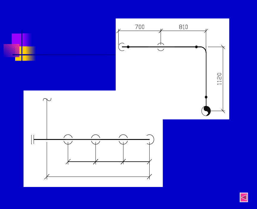
DIMENSIONING OF DRAWINGS
•
Sufficient dimensions to be given for positioning
equipment and for erecting piping.
•
Duplicating dimensions in different views should be
avoided, as this may lead to errors if changes are made.
•
Reserve horizontal dimensions for the plan view.
•
If single pipe is to be positioned or a pipe connected to
nozzle is to be indicated, then show the centre line
elevation and mark as C .
•
If several pipes are sharing a common support, show
elevation of Bottom of Pipes and mark as BOP EL. This
is more applicable to non-insulated lines.

•
In case of several pipes on a pipe rack, show the
“Top of Support” elevation and mark as TOS
EL.
•
In case of buried pipelines in trench, show
elevation of bottom of pipes.
•
In case of drains and sewers, the Invert Elevation
of the inside of the pipe is marked as IE.

•
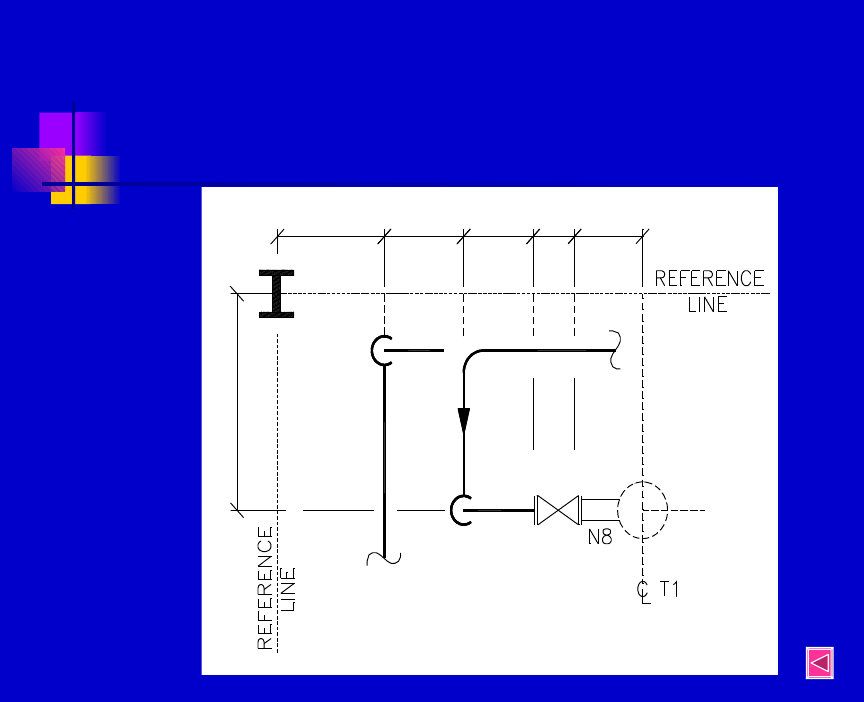
Centre lines of the equipment and pipelines shall be
located with reference to the building column centre lines or
the co-ordinates which can be considered as a reference
base.
•
The distance between the lines shall be dimensioned centre
line to centre line.
•
The horizontal nozzles on the equipment shall be located
from centre to flange face in plan. For vertical nozzles show
Face of Flange elevation (FOF).
•
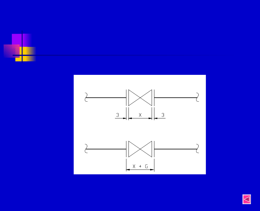
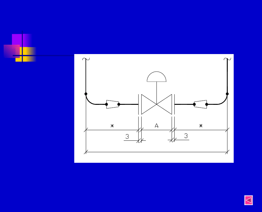
For valves, instruments and non-standard equipments,
show the dimensions from flange face to flange face.

•
Flanged valves are located with dimension to flange faces. Non-
flanged valves are dimensioned to their centres or stems.
•
For flanged joints show a small gap between dimension lines to
indicate gasket. Flanged joints can also be shown without
gasket but
cover the same with a general note and include gasket thickness
in the valve or equipment dimensions.
•
For Finished Floor (FF) the elevation shall be the high point of
•
the floor.

•
For foundation the Top of Grout (TOG) elevation is shown.
•
Show dimensions outside the drawn view - do not cut
pictures.
•
Draw dimension line unbroken with fine line. Write
dimension just above the horizontal line. For vertical lines
write sideways.
•
The dimension lines can be terminated with arrow heads or
oblique dashes.
•
If series of dimension is to be shown, string them together.
•
Show overall dimension of the string of dimensions. Avoid
one of the break-up dimensions to omit repetition and error
during changes.
•
Do not omit significant dimension other than fitting make
up.

•
For field run piping, give only those dimensions which are
necessary to route piping clear of equipments and other
obstructions. Locate only those items which are important
to
the process.
•
Underline out of scale dimensions or mark as NTS.
•
Do not terminate dimensions at screwed or welded joints.

CHECKING OF PIPING DRAWINGS
Checking shall be done only on the print or the
check plot of the drawings and by coloured
pencils/pens.
A. Corrected areas and dimensions are marked yellow.
B. Areas and dimensions which are to be deleted are
marked green.
C. Areas to be corrected/incorporated on the drawing
are marked in red.
The new print after correction is “back checked” for
incorporation.
Points to be checked on the piping drawing includes:
Title of the drawing.

•
Title of the drawing.
•
Orientation - North arrow against plot plan.
•
Inclusion of graphic scale (if drawings is to be reduced).
•
Co-ordinates of equipments against equipment layout.
•
Equipment numbers and their appearance on the piping
drawing.
•
Correct identification on all lines in all views.
•
Line specification changes.
•
Reference drawing numbers and files.
•
Correctness of all dimensions.
•
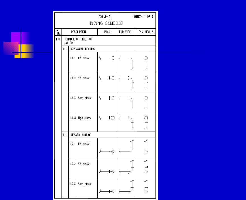
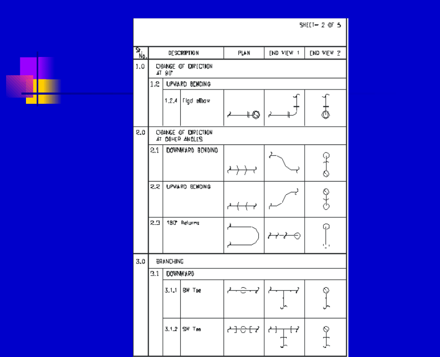
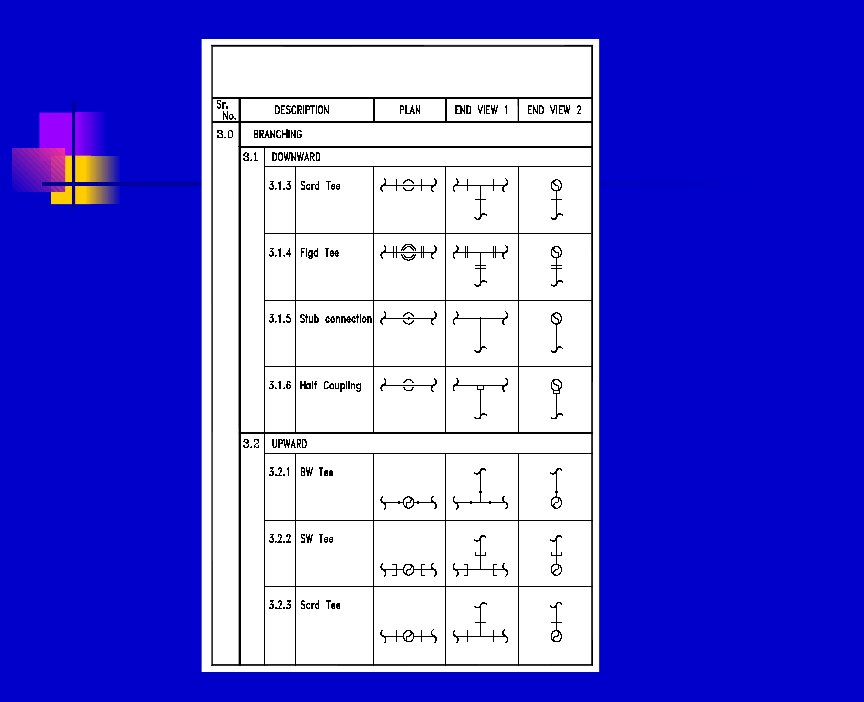
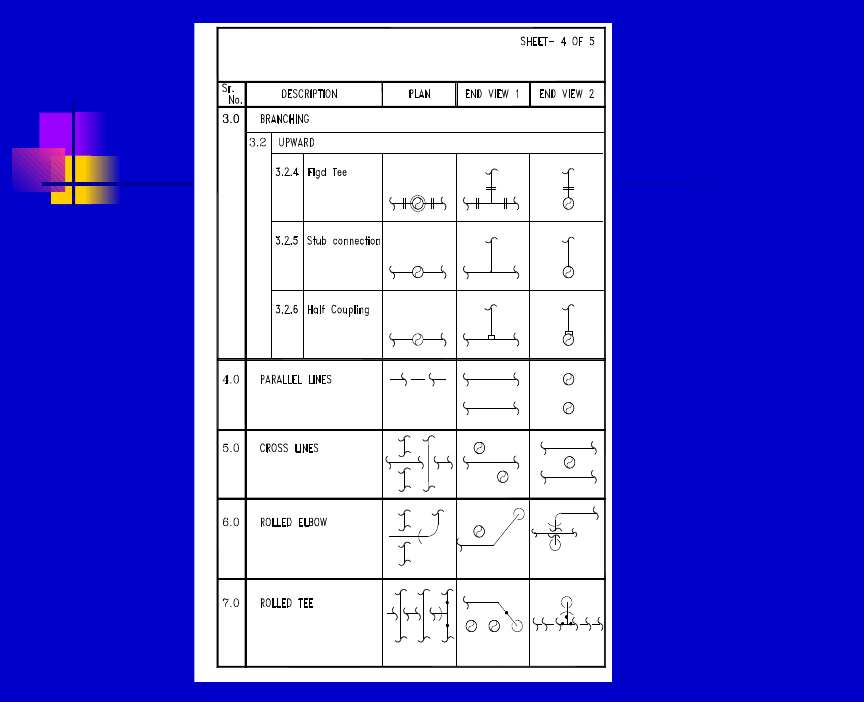
Whether representation is correctly made in line with
the standard symbols or not.
•
Location and identification of all instruments.
Requirements of upstream/downstream straight lengths.
•
Insulation requirements as per P&IDs.
•
Piping arrangement against P&ID requirements such as
gravity flow, seals, etc.
•
Possible interference
•
Floor and wall openings.

•
Correctness of scale in case of General Arrangement
Drawings
•
Whether all stress analysis requirements are met or not
•
Adequacy of clearance from civil structures, electrical
apparatus and instrument consoles.
•
Accessibility of operation and maintenance space and
provision of drop out and handling areas.
•
Foundation drawings and vendor equipment requirements
•
Details and section identification match.
•
“Matchline” provision and accuracy.
•
Presence of signatures and dates.
•
Accuracy of BOM in Isometrics.
•
Number of issues and revision.
********
Wyszukiwarka
Podobne podstrony:
Eaton VP 33 76 Ball Guide Unit Drawing
Fashion Artist Drawing Techniques to Portfolio Presentation
2009 11 17 arduino basics
LV Basics I (2)
Excel VBA Course Notes 1 Macro Basics
Anime drawing tutorials [ENG]
CATIA V5 Training Basics
LAB 18mm drawing 4
K3V180DPDT Parts Drawing
027 drawing swer distr trf 32 kva english
AT2H Basics Hindu Culture Part 2
Drawing1 recover000 recover recover Layout1 (1)
AT2H Basics Education in Ancient India
Nowy VISIO 4 Drawing vsd
Basics I
Basics of Assembler
Finished drawing for air reservoir,pressure tank,calorifer
P001034 A Fin Mechanical drawings
więcej podobnych podstron