
361
In This Chapter
15
Creating Table Driven Parts
You can assign variables to the parametric dimensions
that control a generic part and then use a table (an
external spreadsheet) to control the size and shape of
the part. The spreadsheet can contain several versions of
the part. Each version uses different values for the
variables you define. Autodesk
®
Mechanical Desktop
®
redraws the part using the variables linked to that
version.
Documentation for all versions can be simplified by
plotting one drawing representing the generic part. You
can paste the spreadsheet into your drawing to list the
values for each version.
For this tutorial, you need Microsoft
®
Excel on your
system.
■
Creating a table
■
Displaying part versions
■
Editing a table
■
Solving common problems with
table driven parts
■
Suppressing features in table
driven parts
■
Setting up a generic drawing to
define the table driven part

362
|
Chapter 15
Creating Table Driven Parts
Key Terms
Term
Definition
active part variable
A parametric variable used in the dimensions that control features of the active
part.
feature suppression
Temporarily removing features from the calculation of a part. Features can be
suppressed manually through the Desktop Browser, or through a linked external
table.
global variable
A parametric variable that can be used by any number of parametric features and
parts. Also used for single parts and to constrain parts.
linked spreadsheet
An external spreadsheet linked to the current drawing file. This spreadsheet can
be used to change parts in the drawing file, if the variables in the spreadsheet are
used in the drawing file.
manual suppression
Suppressing features through the browser or command line. These features will
remain suppressed unless manually unsuppressed or a version of a linked table
that unsuppresses it becomes active.
part version
The version of variables that the active part is currently using from the external
table. Part versions can be changed through the Desktop Browser or the Design
Variables dialog box.
table
An external spreadsheet that drives versions of a part.
table driven
suppression
Features suppressed in an external spreadsheet. A table driven suppressed feature
is suppressed only in the part version specified in the spreadsheet.
table driven variable
A global or active part design variable controlled by values in a linked external
spreadsheet.
Basic Concepts of Table Driven Parts
|
363
Basic Concepts of Table Driven Parts
In the manufacturing industry, you often have parts that are similar to each
other except for size or a particular feature. Some examples are springs, brackets,
plates, nuts, and bolts. By driving part versions from an external spreadsheet,
you can document a number of similar parts using one drawing.
The external spreadsheet, or table, is where you make modifications to your
design specifications once your drawing is set up. By controlling a part from
a table, you avoid errors due to design changes that have not been imple-
mented across a number of drawings. All design data is contained in the
table, with one drawing representing many parts.
Open the file tdpart1.dwg in the desktop\tutorial folder.
NOTE
Back up the tutorial drawing files so you still have the original files if you
make a mistake. See “Backing up Tutorial Drawing Files” on page 40.
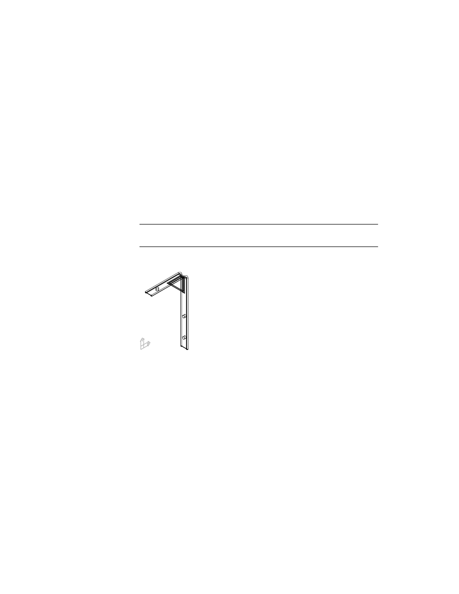
The drawing is a simple bracket that you link to a spreadsheet.
The part is controlled by its relationships to nine active part design variables.
Changing the value of one variable affects every dimension that has a rela-
tionship to it. For information on creating and modifying design variables,
see chapter 11, “Using Design Variables.”
364
|
Chapter 15
Creating Table Driven Parts
Setting Up Tables
A table is a spreadsheet that contains the various part versions and the values
of the design variables for each version. You use Microsoft Excel to create
table driven parts.
First, examine the part, using the Desktop Browser. Expand the Browser by
clicking the plus sign in front of TDPART1 and PART1_1. The bracket is con-
structed from three extrusions, three holes, and five fillets.
Each feature is controlled by a design variable. In this exercise, you create a
table containing the design variables, and define four different part versions.
To set up a table
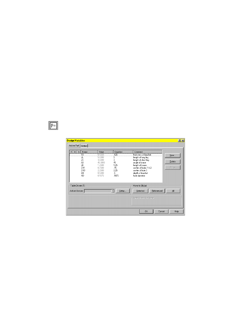
1
Use
AMVARS
to open the Design Variables dialog box and set up a table.
Desktop Menu
Part ➤ Design Variables
2
In the Design Variables dialog box, verify that the Active Part tab is selected.
Examine the active part design variables.
3
Under Table Driven, choose Setup.
4
In the Table Driven Setup dialog box, verify that the Active Part tab is
selected. Under Layout, specify:
Version Names:
Across
Choose Create.
Setting Up Tables
|
365
5
In the Create Table dialog box, select the desktop\tutorial folder and specify
tdpart1.xls as the name of your table.
Choose Save to exit the dialog box.
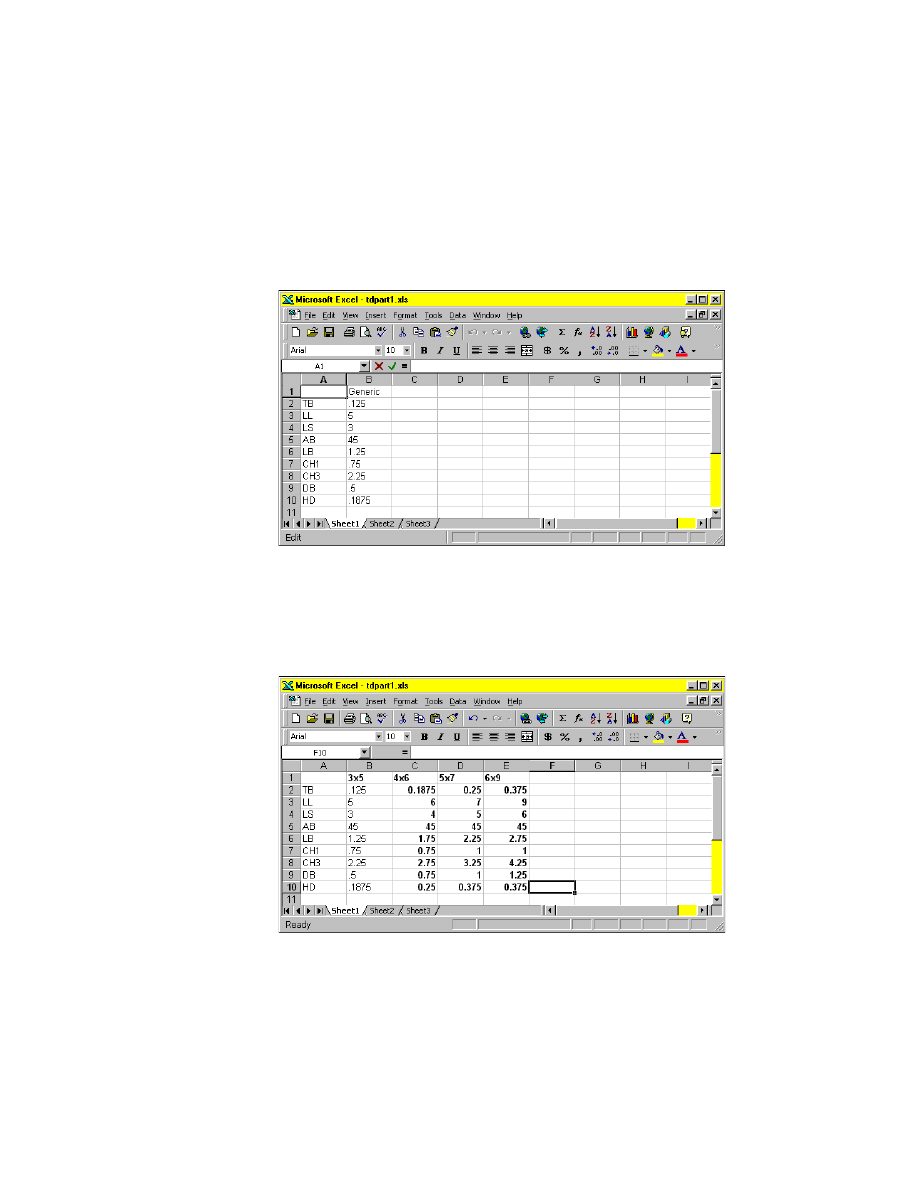
Microsoft Excel opens a new spreadsheet containing a generic part and a
value for each design variable assigned to it.
Next, change the name of the generic part to 3
5 and add three more part
versions.
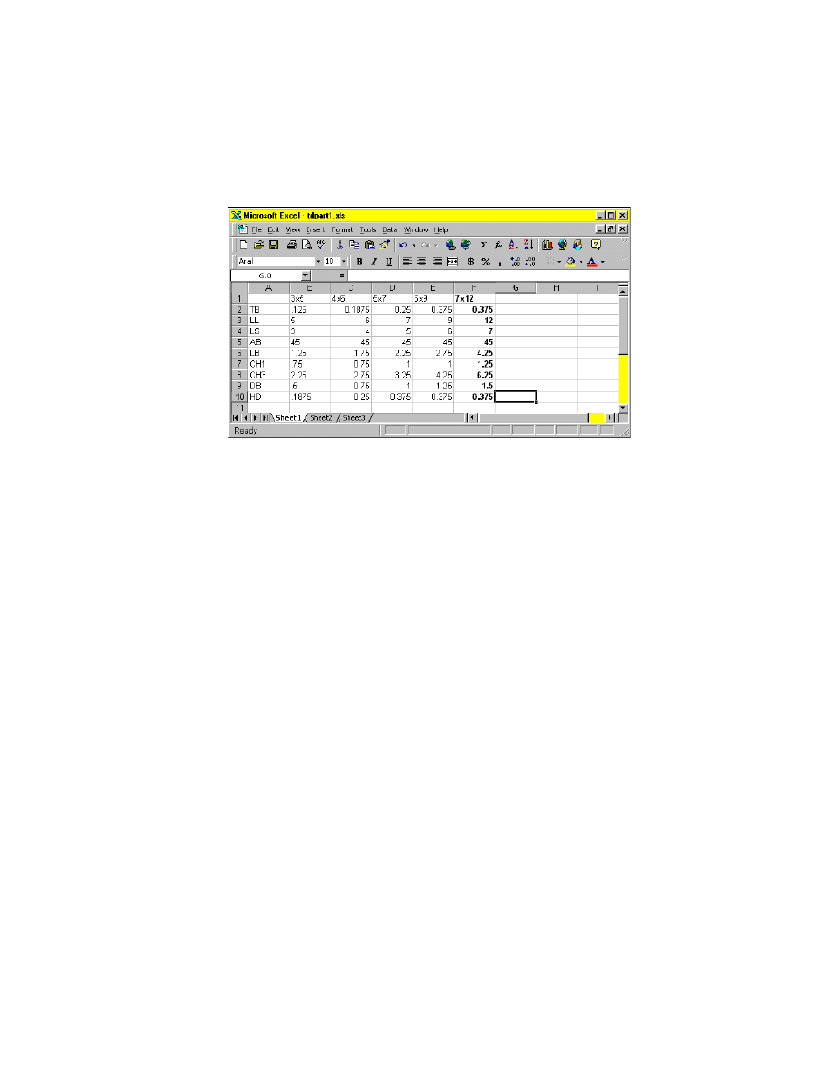
To define additional part versions
1
Fill in the value of the design variable for each new part definition, as shown
in the following illustration:
2
Save the file and exit Microsoft Excel.
366
|
Chapter 15
Creating Table Driven Parts
3
In the Table Driven Setup dialog box, select Update Link and choose OK.
Choose OK to exit the Design Variables dialog box.
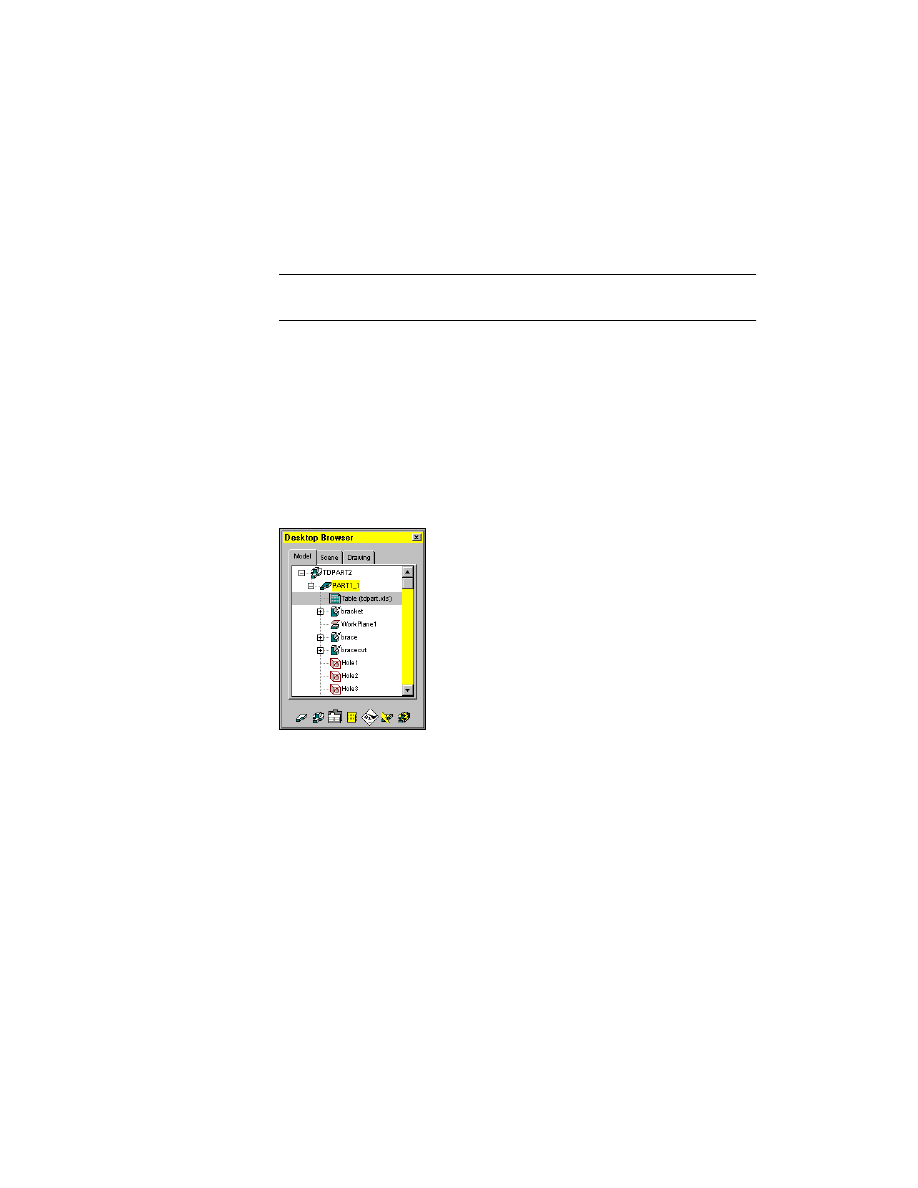
The Desktop Browser now contains a Table icon nested below PART1_1. The
four part versions you created in the spreadsheet are listed below the Table
icon.
The PART1_1 (3
5) icon displays the active version in parentheses. The Table
(tdpart1.xls) icon indicates the name of the spreadsheet that is linked to your
drawing.
Next, display each version of the table driven part. When you select a ver-
sion, Mechanical Desktop recalculates the part, using the values for the vari-
ables that correspond to the selected version.
Displaying Part Versions
You display part versions by selecting them from the Desktop Browser.
To display a part version
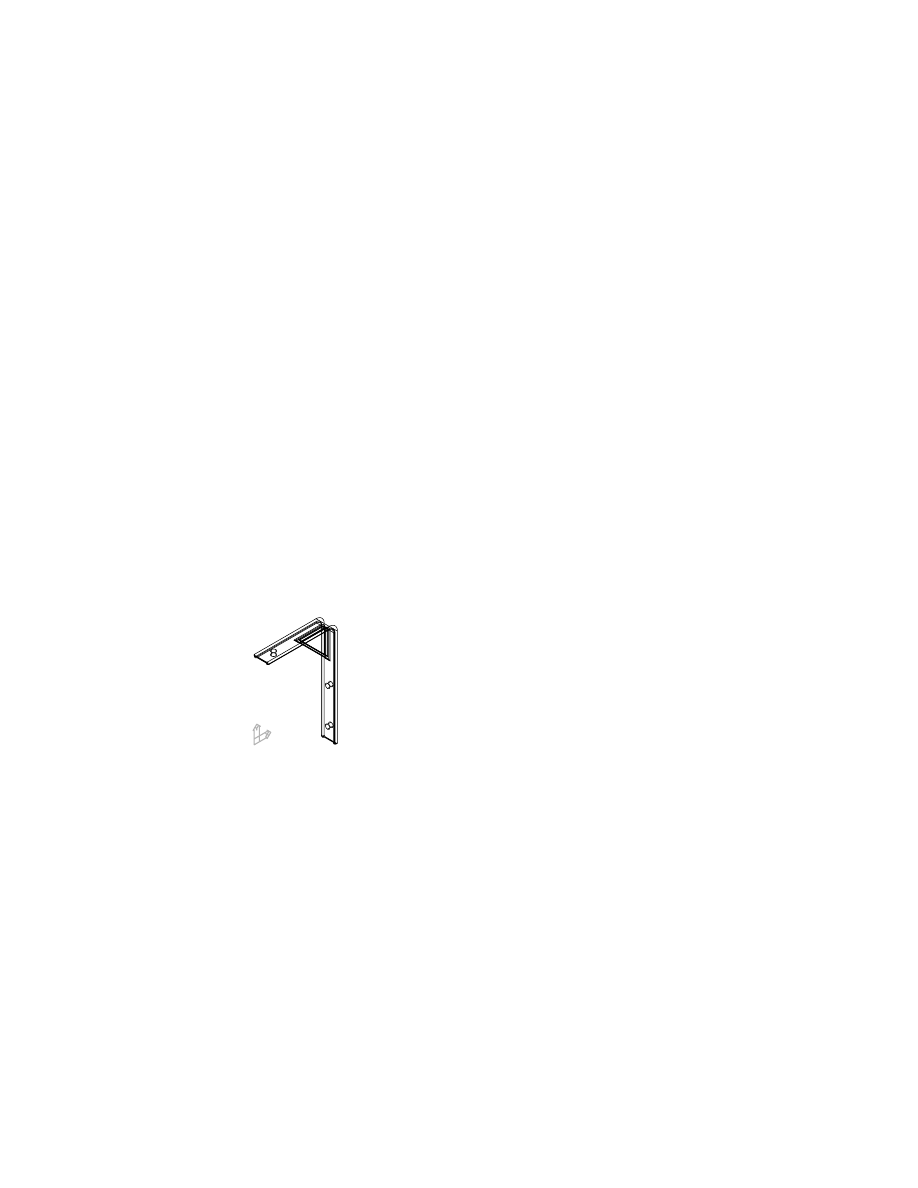
1
Display the 4
6 part version.
Browser
Double-click the 4x6 icon.
The 4x6 version is calculated and displayed.
2
Repeat step 1 for the other two versions.
The part versions do not differ, except in size. In the next lesson, you add
another part version by editing the spreadsheet.

Editing Tables
|
367
Editing Tables
Using a table to drive multiple versions of a part gives you flexibility in
designing the part. You can quickly create variations of the part, and easily
edit the design parameters by changing values in the cells of the spreadsheet.
To add a part version to an existing table
1
Open the spreadsheet to edit.
Browser
Right-click Table (tdpart1.xls) and choose Edit.
NOTE
The part definition in the Browser displays the current version of the
part for easy reference.
Microsoft Excel opens, displaying your spreadsheet.
368
|
Chapter 15
Creating Table Driven Parts
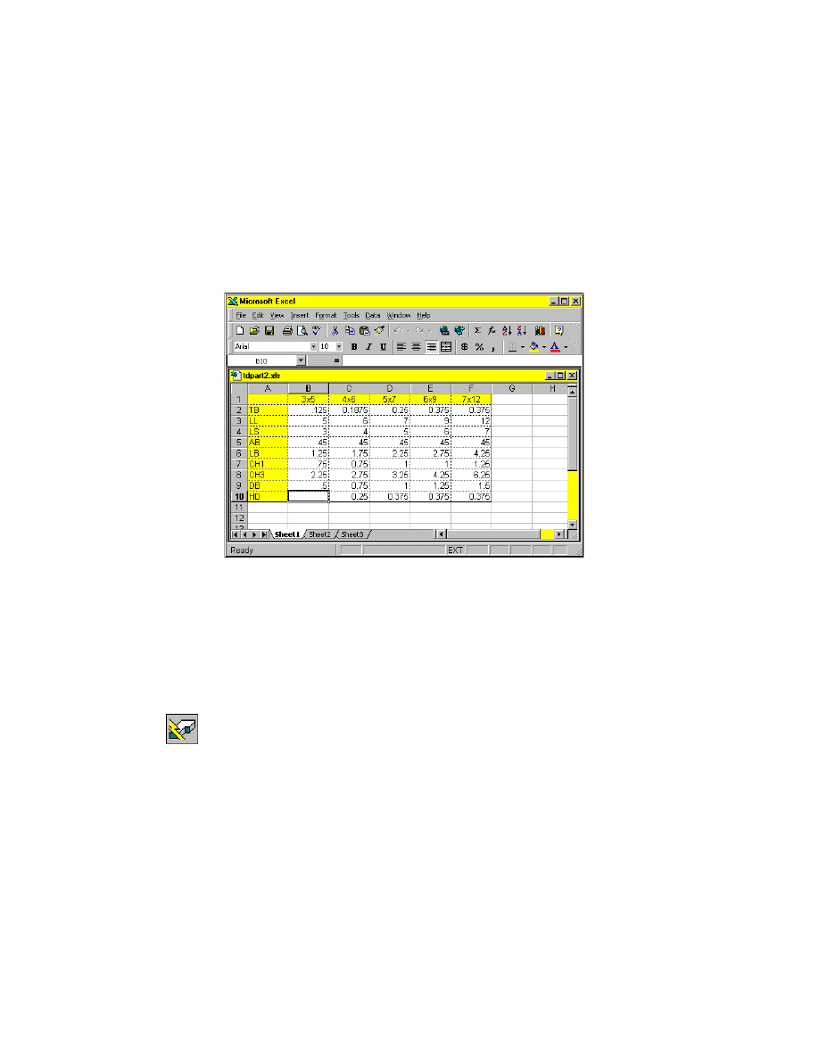
2
Add a new part version in the spreadsheet, using the values in the following
illustration:
3
Save the spreadsheet and exit Microsoft Excel.
4
Update the link to the spreadsheet.
Browser
Right-click Table (tdpart1.xls) and choose Update.
Examine the Browser. It now displays five part versions under the Table
(tdpart1.xls) icon.
Occasionally, errors occur when you link a spreadsheet to Mechanical
Desktop. In the next section, you learn how to fix errors such as
■
Spreadsheets that cannot be found
■
Spreadsheets that have been modified since the drawing was saved
■
Incorrect or missing data in a spreadsheet
Resolving Common Table Errors
|
369
Resolving Common Table Errors
Open the file tdpart2.dwg in the desktop\tutorial folder.
NOTE
Back up the tutorial drawing files so you still have the original files if you
make a mistake. See “Backing up Tutorial Drawing Files” on page 40.
The drawing contains a version of the simple bracket used in the previous
example, but it is linked to a different spreadsheet.
Before you can look for errors in the link between the drawing and the
spreadsheet, you need to expand the part hierarchy.
To expand a part hierarchy
1
Expand the part hierarchy.
Browser
Click the plus sign in front of TDPART2 and then click
PART1_1.
Notice the red background behind the Table icon. This indicates that the
spreadsheet cannot be found, it has been modified since the drawing was last
saved, or it contains incorrect data in one or more cells. Before the spread-
sheet can be used to drive the part, you must resolve the conflict.
370
|
Chapter 15
Creating Table Driven Parts
To resolve a conflict with a linked spreadsheet
1
Resolve the conflict between the drawing and the linked spreadsheet.
Browser
Right-click Table (tdpart.xls) and choose Resolve Conflict.
An AutoCAD message dialog box is displayed asking if you would like to
update the table.
2
In the message dialog box, choose Yes.
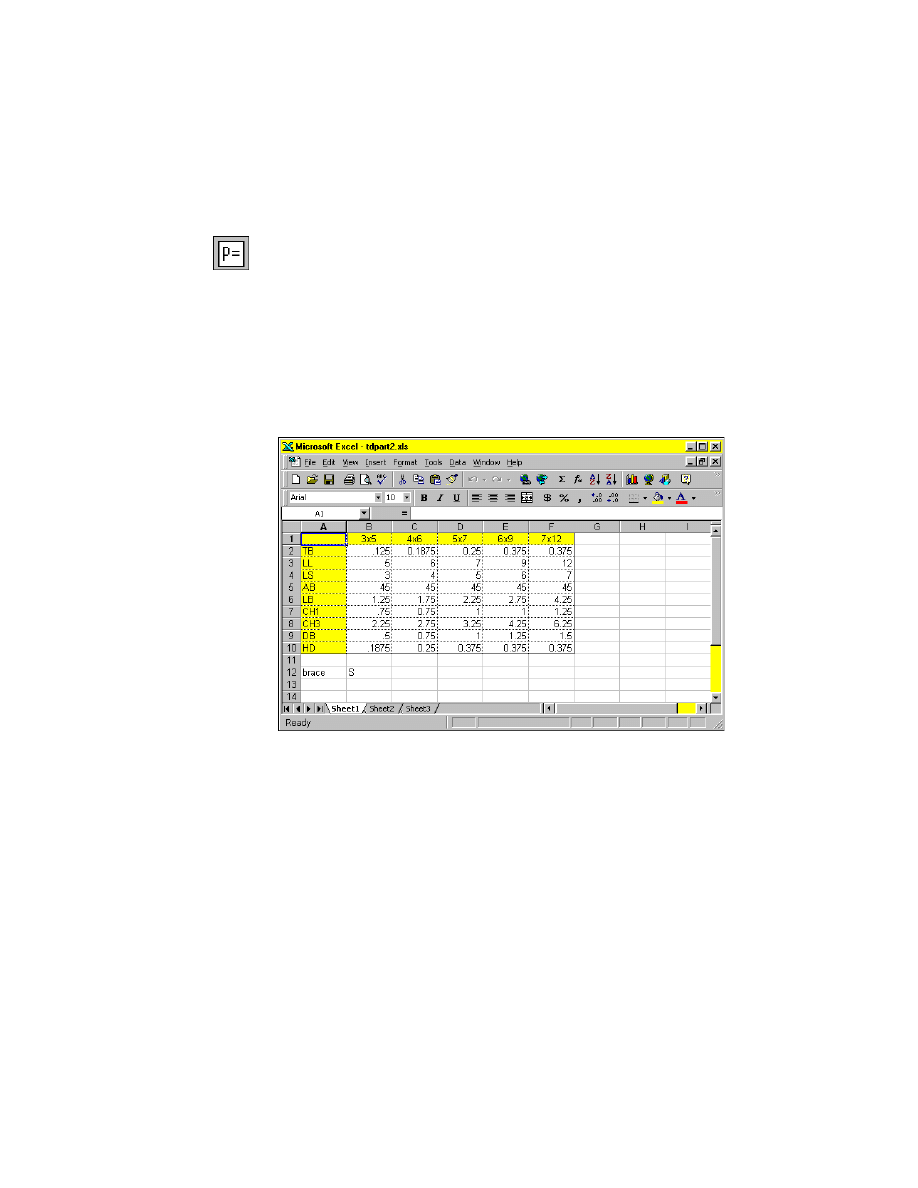
The HD variable controls the diameters of the holes for the bracket. The first
part version is missing an entry in cell B10.
3
In cell B10, enter .1875. Then save the spreadsheet and exit Microsoft Excel.
4
Update the link to the table.
Browser
Right-click Table (tdpart2.xls) and choose Update.
Mechanical Desktop updates the link.
5
Use
AMUPDATE
to update the part.
Context Menu
In the graphics area, right-click and choose Update Part.
Next, display the part versions.

Suppressing Features
|
371
To display the first part version
1
Display the first part version.
Browser
Double-click the 3
5 icon nested under PART1_1.
The 3
5 angle bracket is recalculated from the values in the table and then
displayed.
2
Repeat step 1 for the remaining four part versions.
Save your file.
Next, you suppress features for some of the part versions in your table. The
smaller brackets do not require the brace, so you will suppress the features
associated with it for those versions.
Suppressing Features
Suppressing features can be done in the Browser, in a linked table, or in the
Suppress By Type dialog box. Suppressing a feature manually in the Browser
affects all part versions. Suppressing a table driven feature gives you control
over each version.
Use the Suppress By Type dialog box to suppress and unsuppress features by
specific type.
With an existing table, you append the features you want suppressed to the
table. First, you manually suppress the brace feature and the bracecut feature
in the Browser. It is not important which version of the part is active when
the features are suppressed.
372
|
Chapter 15
Creating Table Driven Parts
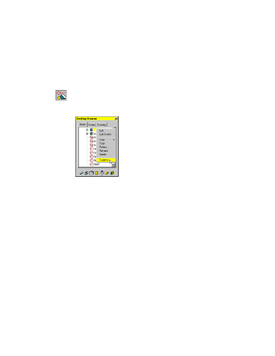
To suppress a feature
1
Display the first part version.
Browser
Double-click the 3
5 icon nested under PART1_1.
2
Use
AMSUPPRESSFEAT
to suppress the brace feature, responding to the
prompt.
Browser
Right-click Brace and choose Suppress.
The highlighted features will be suppressed.
Continue? [Yes/No] <Yes>:
Press
ENTER
The brace feature is suppressed and is no longer visible on your screen. The
bracecut feature and four fillets are dependent on the brace feature, so they
are also suppressed.
Manually suppressed features are represented in the Browser by a circle and
a dashed line preceding the grayed-out feature name. These features can be
unsuppressed at any time.
Next, append the suppressed features to the table.
Suppressing Features
|
373
To append a suppressed feature to a table
1
Use
AMVARS
to append the suppressed features to the spreadsheet.
Desktop Menu
Part ➤ Design Variables
2
In the Design Variables dialog box, under Table Driven, choose Setup.
3
In the Table Driven Setup dialog box, specify:
Type:
Both
Format:
Concatenate Tables
Choose Append.
Microsoft Excel spreadsheet tdpart2.xls is displayed. A new entry, brace, has
been added under the existing design variables. The letter “S” in the 3
5 col-
umn indicates that this feature is suppressed.
Next, suppress the brace and its dependent features for the 4
6 version.
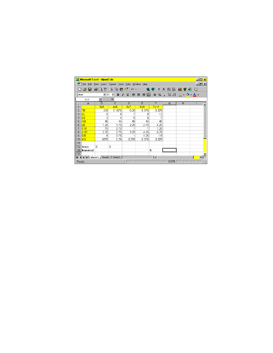
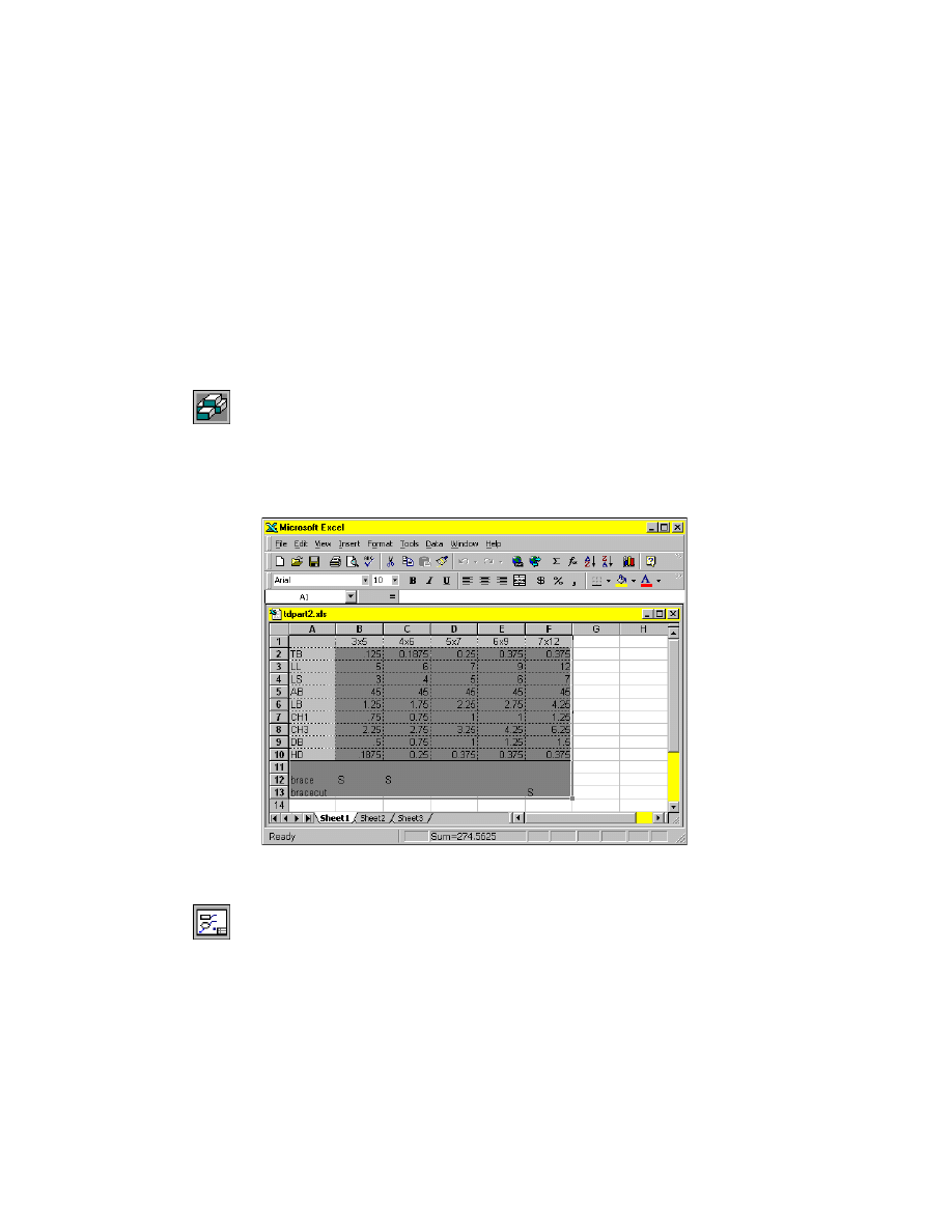
4
In the spreadsheet, enter S in cell C12.
For the largest bracket, you suppress the bracecut feature while retaining the
brace feature for strength.
374
|
Chapter 15
Creating Table Driven Parts
To create a suppressed feature in a table
1
In the spreadsheet, in cell A13 enter bracecut.
2
In cell F13 enter S.
3
Save the spreadsheet and exit Microsoft Excel.
4
Choose OK to exit the Table Driven Setup dialog box without updating the
link.
5
Choose OK to exit the Design Variables dialog box.
You have created two table driven suppressed features. To activate the table
driven suppression of these features, you update the link to the table. After
the table has been linked to the drawing, these features cannot be manually
unsuppressed. To unsuppress these features, you edit the spreadsheet.
Manually suppressed features affect all part versions so you must manually
unsuppress the features in the Browser before you update the link to the
table.
Suppressing Features
|
375
To manually unsuppress a feature
1
Use
AMUNSUPPRESSFEAT
to unsuppress the brace feature.
Browser
Right-click Brace and choose Unsuppress+.
NOTE
By using Unsuppress+ in the Browser, you unsuppress the feature you
select and all dependent features. If you use the Browser, the dialog box is not
displayed.
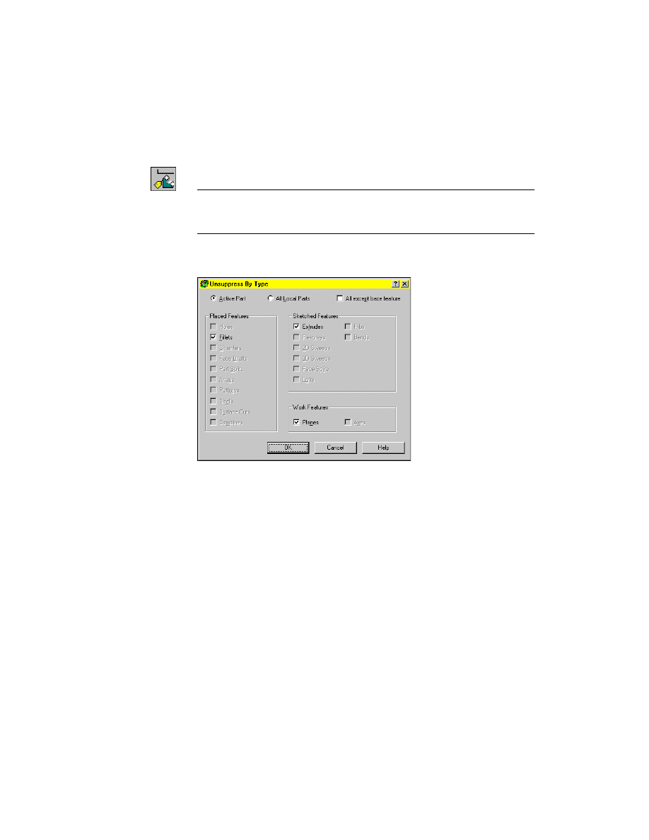
2
If you use the Unsuppress By Type dialog box, verify that Fillets, which are
the dependent features, and Extrudes are selected.
Choose OK.
The brace and its dependent features are unsuppressed. Look at the Browser.
There should be no suppressed features visible.
3
Update the link to the table.
Browser
Right-click Table (tdpart2.xls) and choose Update.
The suppressed features for the active version are now represented in the
Browser by a different symbol. A circle with a diagonal line through it indi-
cates that the feature is suppressed by the table and can be unsuppressed only
by editing the table.
Next, display the 3
5 version of the bracket.
376
|
Chapter 15
Creating Table Driven Parts
To display a part version
1
Display the part.
Browser
Double-click the 3
5 icon nested below Table (tdpart2.xls).
The part is recalculated using the values for the 3
5 version in the linked
table. In the Browser, the suppressed features are grayed out.
2
Repeat step 1 for the 4
6 version. The brace and its dependent features in this
version are suppressed.
3
Repeat step 1 for the 5
7 and 69 versions. Note that the features are not sup-
pressed in these versions.
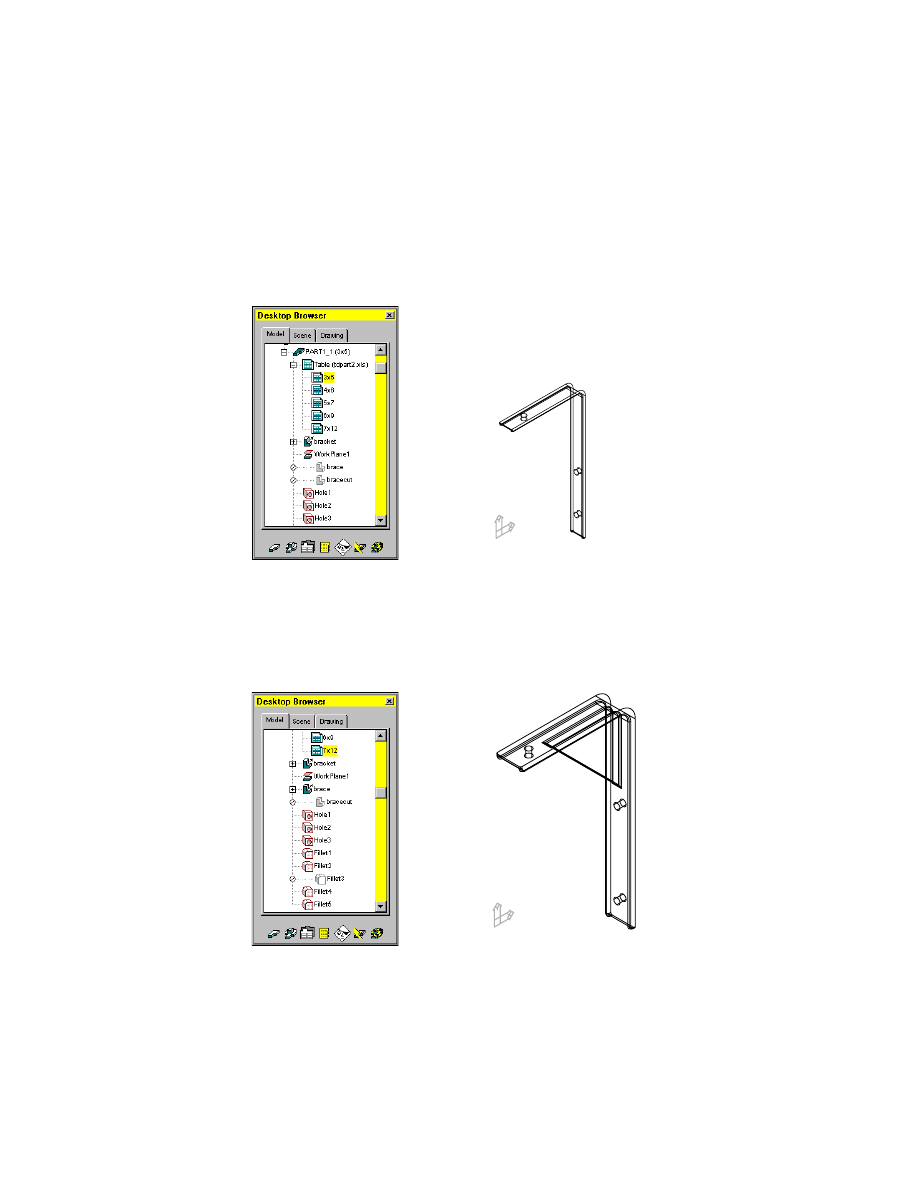
4
Repeat step 1 for the 7
12 version. The brace feature remains in this version,
but the bracecut and its dependent features are suppressed.
Save your file.
3
5 version
7
12 version
Working with Two Part Versions
|
377
Working with Two Part Versions
You can create copies of a part and work with different versions to create
assemblies. In this lesson, you copy a part and display two versions
simultaneously.
To copy a part definition
1
Display the 3
5 version of the bracket.
Browser
Double-click the 3
5 icon nested below Table (tdpart2.xls).
2
Use
UCS
to return to the World Coordinate System so that the copy of the
part is oriented the same as the original.
Desktop Menu
Assist ➤ New UCS ➤ World
3
Use
AMCATALOG
to make a copy of
PART1_1
.
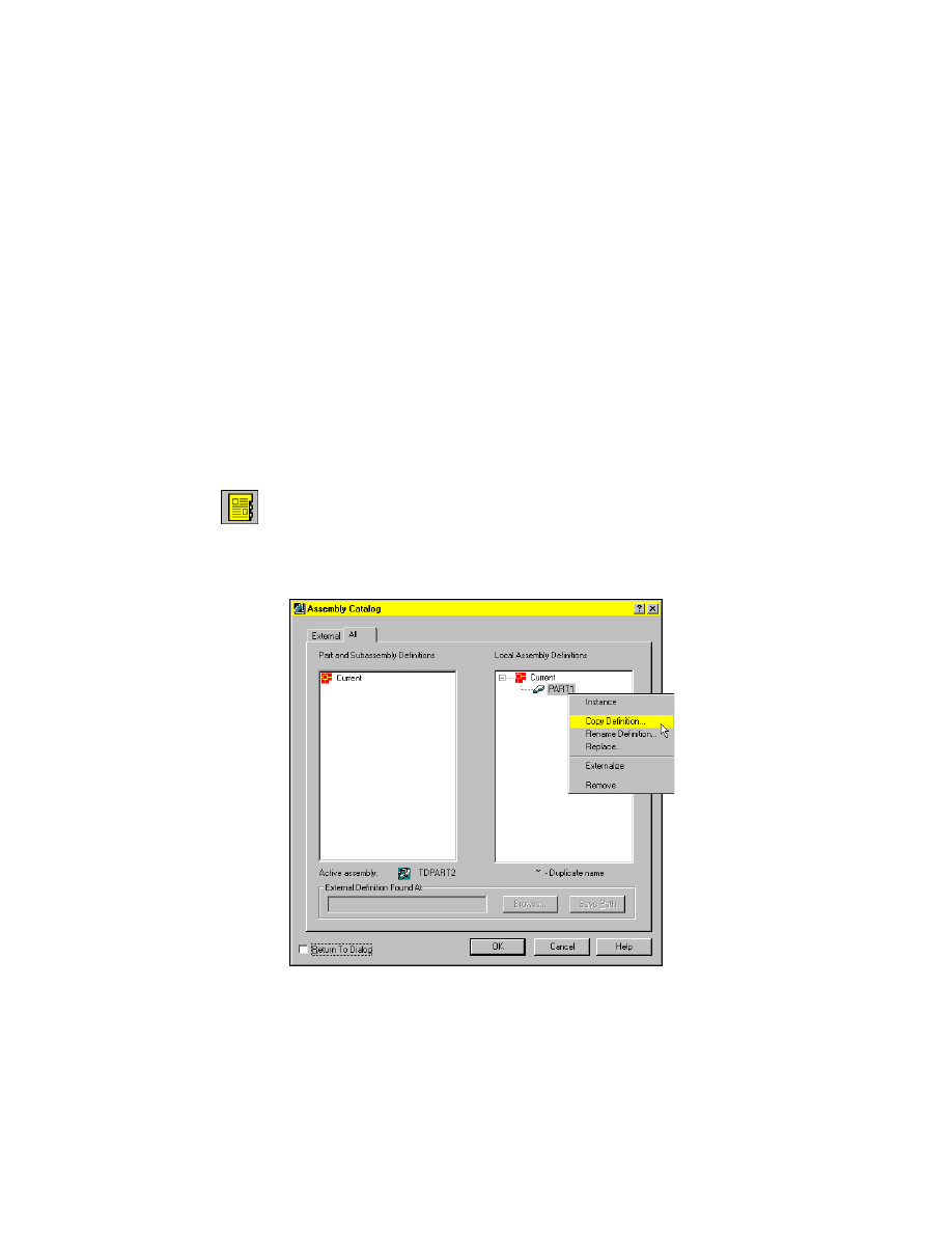
Context Menu
In the graphics area, right-click and choose Catalog.
4
In the Assembly Catalog, clear the Return to Dialog check box and select the
All tab.
5
In Local Assembly Definitions, right-click
PART1_1
and choose Copy
Definition.
378
|
Chapter 15
Creating Table Driven Parts
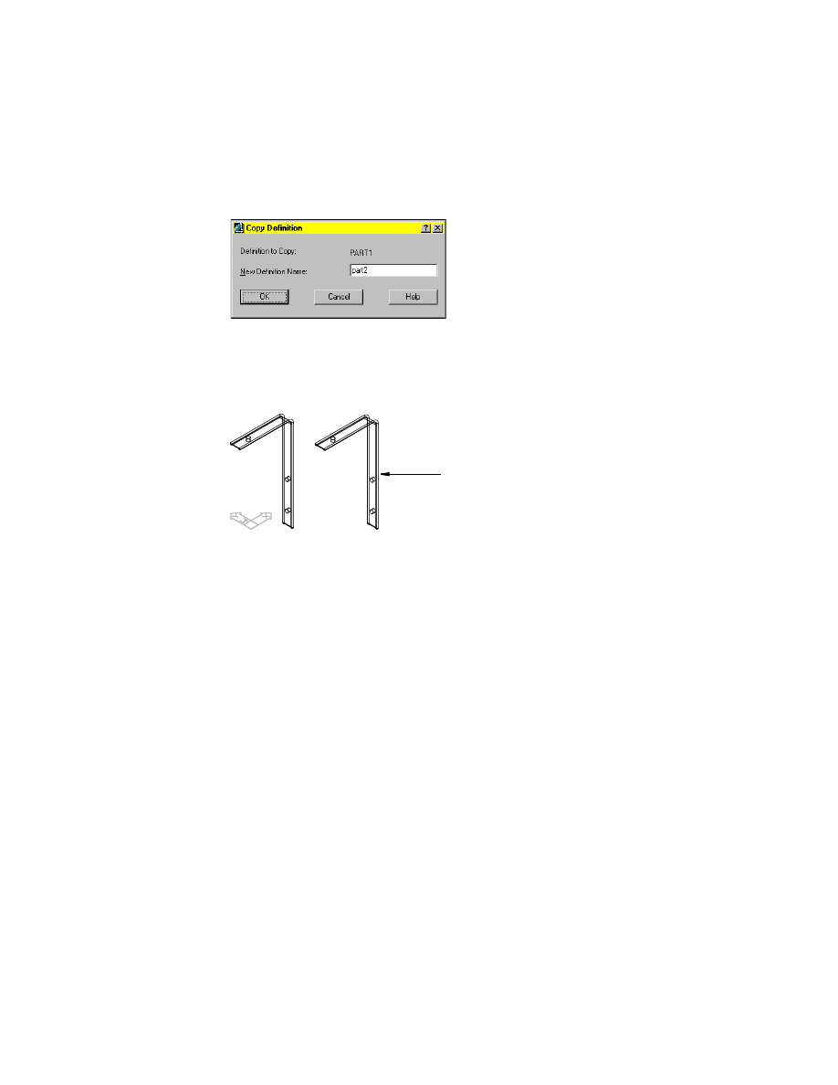
6
In the Copy Definition dialog box, specify:
New Definition Name:
Enter part2
Choose OK.
7
Continue on the command line.
Specify new insertion point:
Specify a point to the right of the existing part
Specify insertion point for another instance or <continue>:
Press
ENTER
Choose OK to close the Assembly Catalog dialog box.
The Browser now contains a
PART2_
1 definition. Because you copied the orig-
inal part definition, its relationship to the spreadsheet, tdpart2.xls, has been
duplicated in the new part.
Next, change the version of the copied part in your drawing.
copied part definition
Creating Drawing Views
|
379
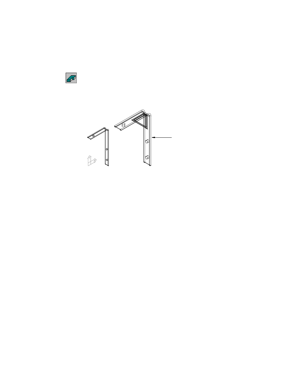
To display a different version
1
Use
AMACTIVATE
to activate
PART2_1
.
Browser
In the Browser, right-click PART2_1 and choose Activate
Part.
2
Display the 5
7 version for
PART2_1
.
Browser
Double-click the 5
7 icon nested under
PART2_1
.
The 5
7 version of
PART2_
1 is displayed.
Save your file.
Next, you set up the drawing for plotting. Instead of using numeric dimen-
sions to annotate five separate parts, you define views for one part and
annotate the drawing, using active part design variables and equations.
You paste into the drawing a copy of your spreadsheet that lists the values
of those variables for each part version.
First, create drawing views to display the part.
Creating Drawing Views
The first view you create is the base view. You define the plane to orient your
view using a part face or work feature, and then position the view in Drawing
mode.
Because you are creating a generic view to represent all versions of the part,
you use the 5
7 version, which contains the brace. When you import the
table, it will indicate the versions for which the brace is suppressed.
PART2_1
380
|
Chapter 15
Creating Table Driven Parts
To create a base view
1
Use the Browser to turn off the visibility of PART1_1.
Browser
Right-click PART1_1 and choose Visible.
2
Use
AMMODE
to switch to Drawing mode.
Browser
Select the Drawing tab.
Mechanical Desktop switches to Drawing mode. A title block has been
inserted into the drawing.
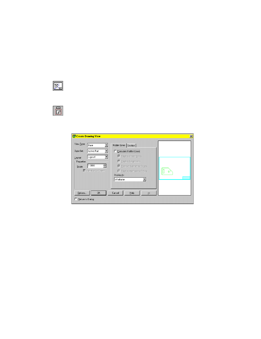
3
Use
AMDWGVIEW
to create the base view.
Context Menu
In the graphics area, right-click and choose New View.
In the Create Drawing View dialog box, select the Hidden Lines tab and specify:
Calculate Hidden Lines:
Clear the check box
Display As:
Wireframe
Choose OK, and continue on the command line.
Select planar face, work plane or [Ucs/View/worldXy/worldYz/worldZx]:
Specify the front edge (1)
Enter an option [Accept/Next] <Accept>:
Enter n to highlight the front face, or press
ENTER
Select work axis, straight edge or [worldX/worldY/worldZ]:
Specify the top edge (2)
Adjust orientation [Flip/Rotate] <Accept>:
Verify that the UCS is upright, and press
ENTER
Creating Drawing Views
|
381
4
Continue on the command line to place the base view.
Specify location of base view:
Specify a point in the top center of the title block
Specify location of base view:
Press
ENTER
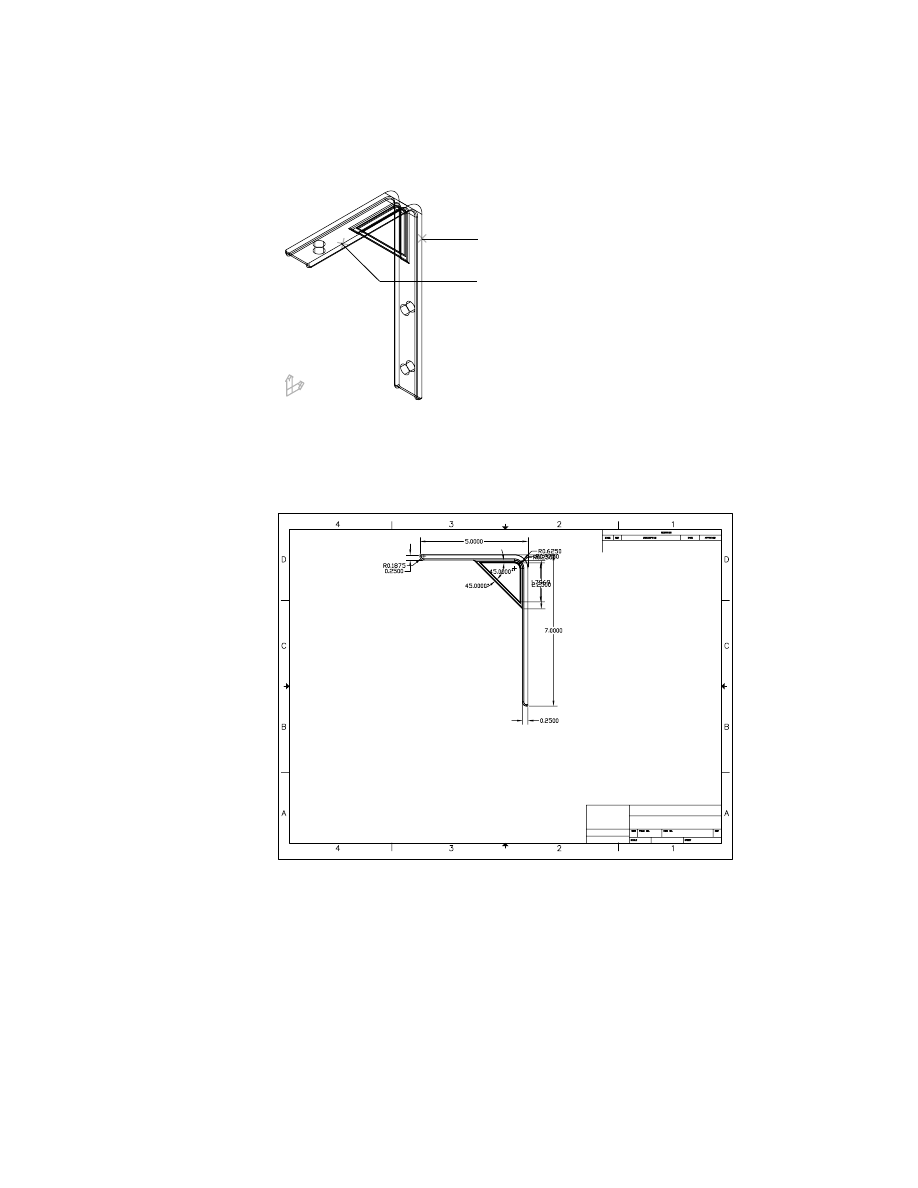
Your drawing should look like this.
Next, create side and bottom orthographic views of the part.
1
2
382
|
Chapter 15
Creating Table Driven Parts
To create an orthographic view
1
Create the orthographic view.
Context Menu
In the graphics area, right-click and choose New View.
2
In the Create Drawing View dialog box, select the view type Ortho. On the
Hidden Lines tab, specify:
Display As:
Wireframe
Choose OK.
3
On the command line, respond to the prompts as follows:
Select parent view:
Pick a point inside the base view
Specify location for orthogonal view:
Specify a point to the left of the base view
Specify location for orthogonal view:
Press
ENTER
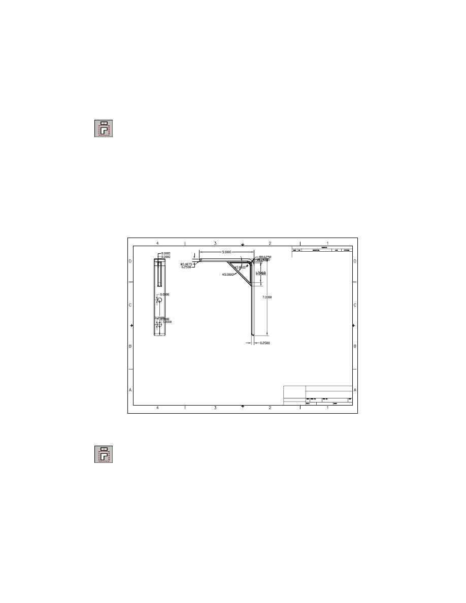
Your drawing should look like this.
Next, create a bottom ortho view.
4
Create the orthographic view.
Context Menu
In the graphics area, right-click and choose New View.
Creating Drawing Views
|
383
5
In the Create Drawing View dialog box, select the view type Ortho. On the
Hidden Lines tab, specify:
Display As:
Wireframe
Choose OK.
6
On the command line, respond to the prompts as follows:
Select parent view:
Pick a point inside the base view
Specify location for orthogonal view:
Specify a point below the base view
Specify location for orthogonal view:
Press
ENTER
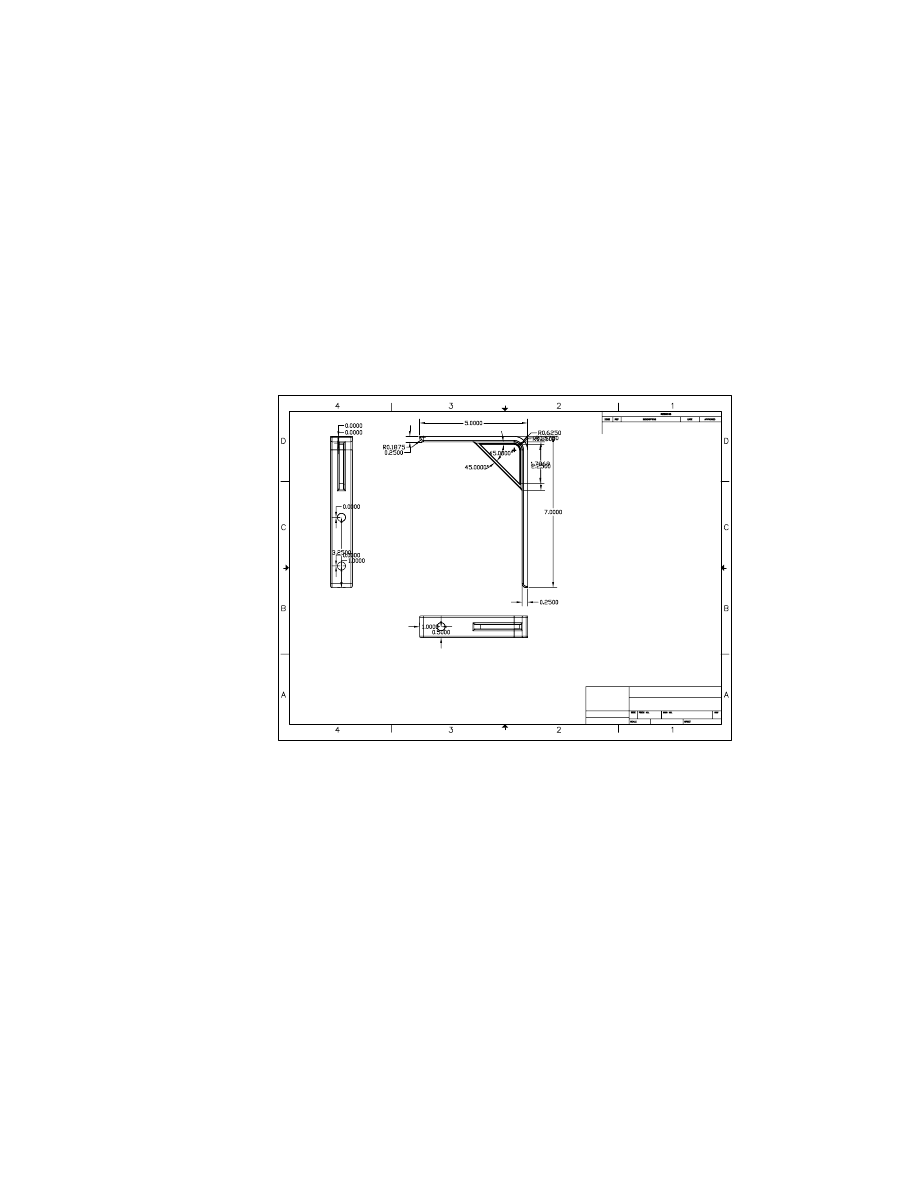
Your drawing should look like this.
Save your file.
Look at the Browser. There are two ortho views and a base view. Because the
ortho views are dependent on the base view, they are nested below the Base
icon.
The parametric dimensions that define the part are displayed in each view.
Because Mechanical Desktop displays the parametric dimensions in the order
in which they were created, dimensions may conflict with each other, over-
lap, or be redundant in a drawing view.
Next, clean up the display of parametric dimensions in each of the views.

384
|
Chapter 15
Creating Table Driven Parts
Cleaning Up the Drawing
To clean up the drawing, you change the parametric dimensions to be dis-
played as parameters, hide extraneous dimensions, and move dimensions for
clarity.
NOTE
For detailed cleanup instructions see “Cleaning Up Drawings” on page
322 in chapter 13.
Displaying Dimensions as Parameters
The parametric dimensions used to define a part are displayed with the val-
ues for the active version of the part. Because you are creating a drawing of
the generic part and linking a table to describe the values for the parameters
controlling each part version, you change dimensions to be displayed as
parameters.
To change a dimension to be displayed as a parameter
1
Display the dimensions as parameters, responding to the prompt.
Desktop Menu
Drawing ➤ Parametric Dim Display ➤ Dimensions as
Parameters
Select dimension or [All/View/Select dimensions] <Select dimensions>:
Enter a
Cleaning Up the Drawing
|
385
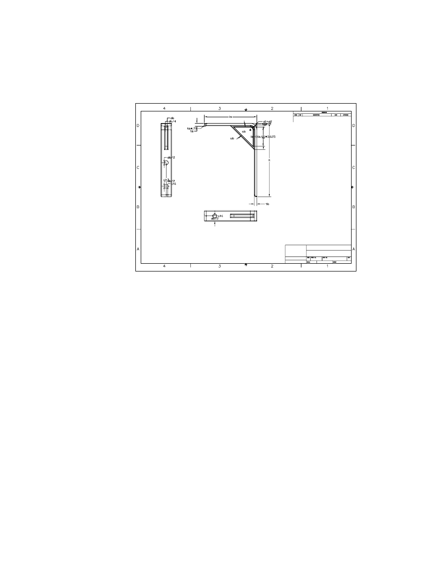
Your drawing should look like this.
Next, hide the extraneous dimensions.
Hiding Extraneous Dimensions
When drawing views are created, Mechanical Desktop displays all the para-
metric dimensions that are related to the part display in each view. Usually,
some cleanup is required because of overlapping or redundant dimensions.
386
|
Chapter 15
Creating Table Driven Parts
To hide an extraneous dimension in a base view
1
Use
AMVISIBLE
to hide extraneous dimensions.
Desktop Menu
Drawing ➤ Drawing Visibility
In the Desktop Visibility dialog box, choose Select.
NOTE
If you choose the toolbutton method to hide the dimensions, the
Desktop Visibility dialog box is not displayed. Select the dimensions to hide. Use
Zoom Realtime while selecting the dimensions.
2
Respond to the prompts as follows:
Select drawing objects to hide:
Specify the d1+d2 dimension (1)
Select drawing objects to hide:
Specify the ab dimension (2)
Select drawing objects to hide:
Specify the tb dimension (3)
Select drawing objects to hide:
Specify the tb dimension (4)
Select drawing objects to hide:
Press
ENTER
In the Desktop Visibility dialog box, choose OK.
3
2
1,4
Cleaning Up the Drawing
|
387
To hide a dimension in an orthographic view
1
Use
AMVISIBLE
to hide dimensions.
Desktop Menu
Drawing ➤ Drawing Visibility
2
In the Desktop Visibility dialog box, choose Select.
NOTE
If you choose the toolbutton method to hide the dimensions, the
Desktop Visibility dialog box is not displayed. Select the dimensions to hide.
3
In the side ortho view, hide the db dimension, the two db/2 dimensions, and
the db/4 dimension.
You do not need to hide dimensions in the bottom ortho view.
The ortho views should look like this.
Now that the extraneous dimensions are hidden, it is easier to move the
remaining dimensions for clarity.
Moving Dimensions
Because several of the remaining dimensions overlap, you need to rearrange
them so that they are easy to view.
side view
bottom view
388
|
Chapter 15
Creating Table Driven Parts
To move a dimension
1
Use
AMMOVEDIM
to move the parametric dimensions in the base view,
responding to the prompts.
Context Menu
In the graphics area, right-click and choose Edit
Dimensions ➤ Move Dimension.
Enter an option [Flip/Move/move mUltiple/Reattach] <Move>:
Press
ENTER
Select dimension to move:
Select the dimension for the long leg of the bracket (1)
Select destination view:
Specify a point in the base view (2)
Select location:
Specify a point to the right (3)
Select location:
Press
ENTER
1
2
3
Cleaning Up the Drawing
|
389
2
Continue moving dimensions until your base view looks like this.
3
Move the dimensions in the ortho views.
The ortho views should look like this.
Next, add reference dimensions, to fully define the part.
side view
bottom view
390
|
Chapter 15
Creating Table Driven Parts
Enhancing Drawings
To finalize the presentation of the drawing, you add power dimensions, dis-
played as parameters and create a hole note to describe the three holes in the
bracket.
Creating Power Dimensions
The drawing views are intended to display the generic part. When you dis-
play parametric dimensions using design variables, and you power dimen-
sion your drawing views, the views represent the generic part.
Because reference dimensions are not displayed as parameters, you use power
dimensioning to create dimensions represented as parameters. Power dimen-
sioning allows you to specify tolerance and fit information for your parts as
you dimension and to modify the default value of a dimension as you create it.
Later, when you paste the spreadsheet into the drawing, you will have a list
of values for the variables in each version that cross-references the dimen-
sions in each view.
To add a reference dimension
Before you begin this procedure, enable Osnaps. If Osnaps are set to off, you
will be unable to create the dimension. Work in the base view.
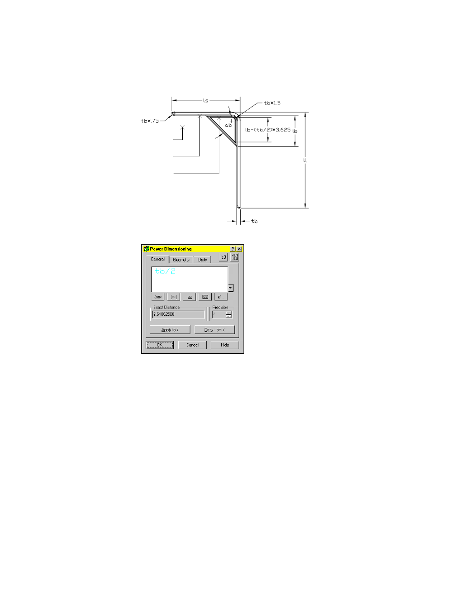
1
Use
AMPOWERDIM
to create power dimensions, responding to the prompts.
Context Menu
In the graphics area, right-click and choose Power
Dimensioning.
(Single) Specify first extension line origin or [Angular/Options/Baseline/Chain/
Update] <Select>:
Specify a point at the bottom of the short leg (1)
Specify second extension line origin:
Specify a point at the inside top of the bracecut (2)
Place dimension line [Options/Pickobj] <Options>:
Specify a location (3)
Enhancing Drawings
|
391
2
In the Power Dimensioning dialog box, change the default text to tb/2.
Choose OK.
3
1
2
392
|
Chapter 15
Creating Table Driven Parts
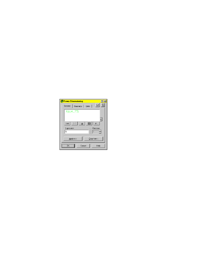
3
Continue on the command line to add a power dimension to the fillet at the
bottom of the long leg:
(Single) Specify first extension line origin or [Angular/Options/Baseline/Chain/
Update] <Select>:
Press
ENTER
Select arc, line, circle, or dimension:
Specify the arc
Enter an option [Next/Accept} <Accept>:
Press
ENTER
Specify dimension line location or [Linear/Diameter/Options]:
Specify a location for the dimension
(Single) Specify first extension line origin or [Angular/Options/Baseline/Chain/
Update] <Select>:
Press
ENTER
Select arc, line, circle, or dimension <Exit>:
Specify the dimension
4
In the Power Dimensioning dialog box, specify tb*.75 for the dimension text.
Choose OK.
5
Continue on the command line.
Select arc, line, circle, or dimension <Exit>:
Press
ENTER
Enhancing Drawings
|
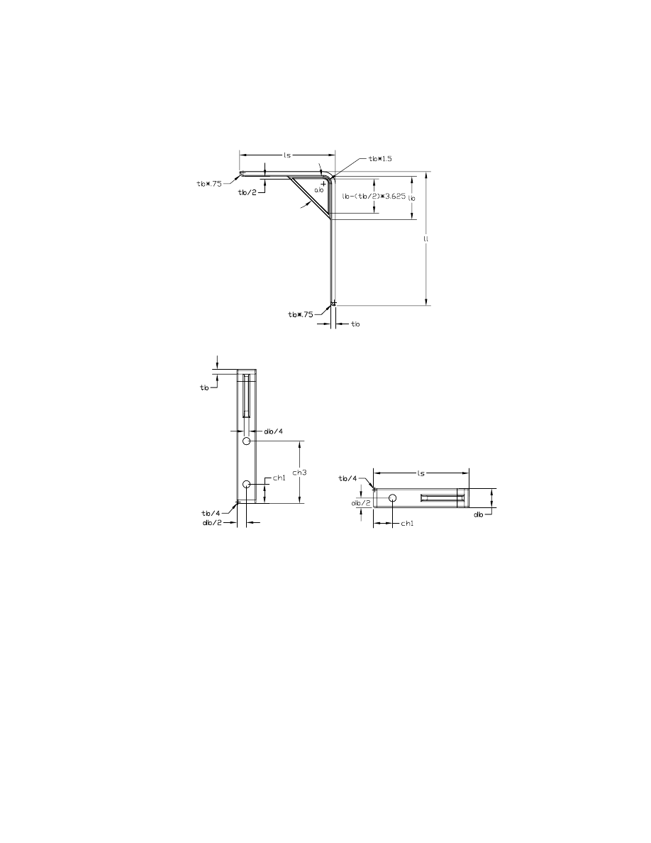
393
Your drawing should resemble the following illustration.
6
Place power dimensions so that the orthographic views look like this.
Next, create a hole note that describes the three holes in the bracket.
Creating Hole Notes
Mechanical Desktop provides a tool for creating hole notes, which saves you
time when annotating your drawing.
In the side view, create a hole note for one of the holes in the long leg of the
bracket.
394
|
Chapter 15
Creating Table Driven Parts
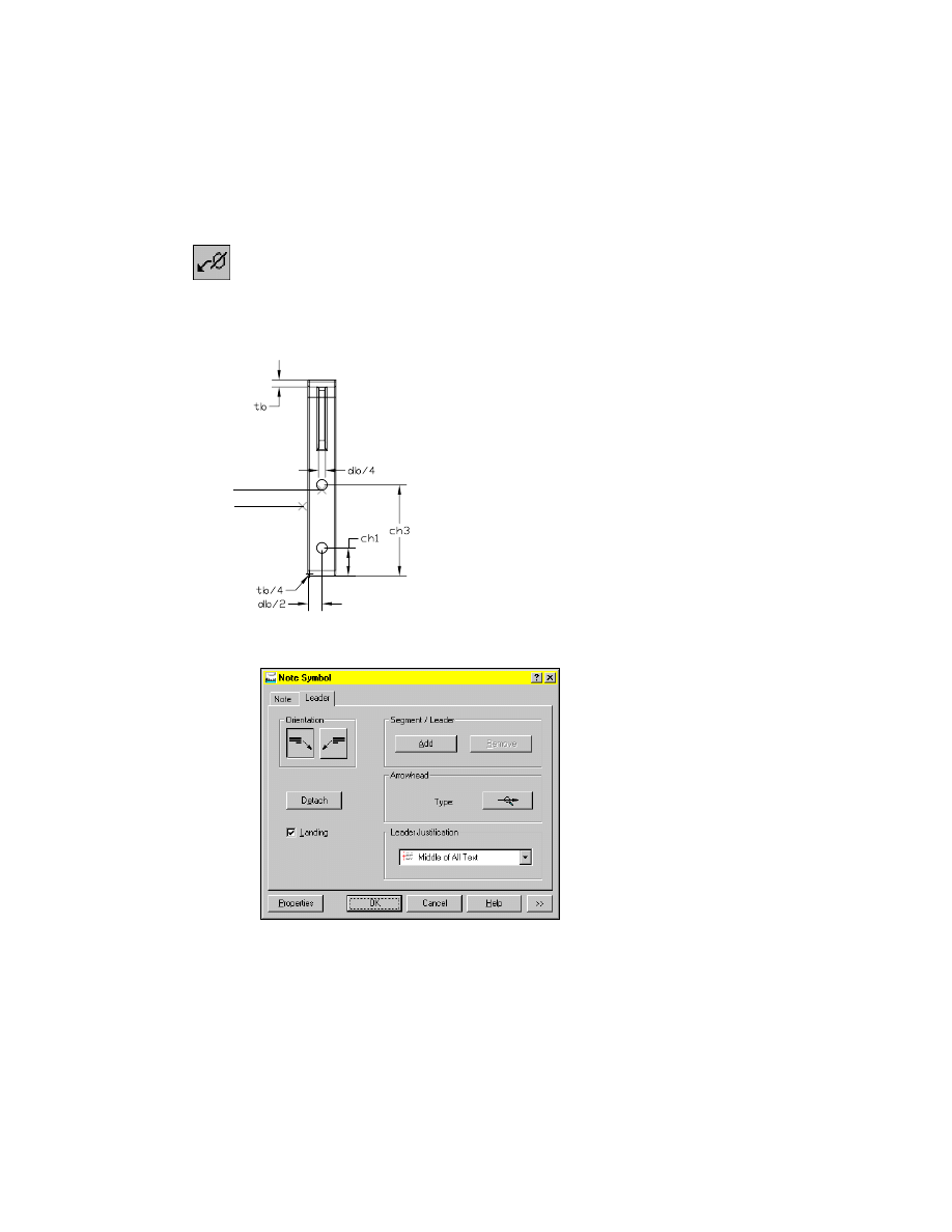
To create a hole note
1
Use
AMNOTE
to create the hole note, responding to the prompts.
Context Menu
In the graphics area, right-click and choose Annotation ➤
Hole Note.
Select object to attach [rEorganize]:
Specify the upper hole in the long leg of the bracket (1)
Next Point <Symbol>:
Specify the location (2) and press
ENTER
.
2
In the Note Symbol dialog box, select the Leader tab. In Leader Justification,
specify Middle of All Text.
Choose OK.
The hole note is displayed in your drawing.
1
2
Enhancing Drawings
|
395
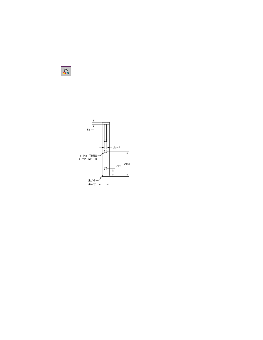
Edit the hole note so that it is typical for all three holes.
3
Use
AMPOWEREDIT
to edit the hole note, responding to the prompt.
Context Menu
Select the hole note, then right-click the note and choose
Edit.
4
In the Note Symbol dialog box, select the Note tab, and change the text to
read as follows:
%%c hd THRU
(typ of 3)
Choose OK.
The side view should now look like this.
Save your file.
Now that the power dimensions and annotations are in place, paste the
linked spreadsheet into the drawing.
396
|
Chapter 15
Creating Table Driven Parts
Pasting Linked Spreadsheets
Pasting a linked spreadsheet into a drawing provides more flexibility for
working with the table that defines the values for the part versions. The
external spreadsheet can be opened and modified while you are working, and
the results are reflected in the drawing.
To paste a linked spreadsheet into a drawing
1
Use
AMMODE
to return to the Part/Assembly environment.
Browser
Select the Model tab.
2
Open the spreadsheet.
Browser
Right-click Table (tdpart2.xls) and choose Edit.
The Microsoft Excel spreadsheet is displayed.
3
Select the cells to be copied.
4
In Microsoft Excel, choose Edit ➤ Copy.
5
In the drawing, return to Drawing mode.
Browser
Select the Drawing tab.
Pasting Linked Spreadsheets
|
397
6
Paste the selected area of the spreadsheet into the drawing.
Desktop Menu
Edit ➤ Paste Special
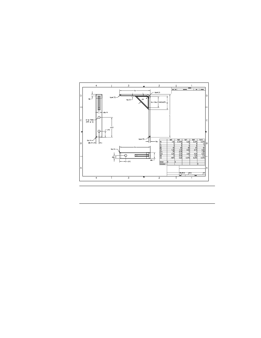
7
In the Paste Special dialog box, choose Paste Link.
8
Place the selected cells in the drawing. Your drawing should look like this.
NOTE
Depending on the zoom factor of your display at the time you paste the
image, you may have to resize it. Select the image, and use a corner grip to resize
it to fit in the drawing.
Save your file.
Now that the linked spreadsheet has been pasted into the drawing, any
changes made in the spreadsheet will automatically be reflected in the draw-
ing. Experiment with modifications to the spreadsheet to see how your part
and the table are automatically updated.

398
Wyszukiwarka
Podobne podstrony:
Genomes3e ppt ch15
Okidata Okipage 14e Parts Manual
oak dining table
Kyocera FS 1010 Parts Manual
Brother PT 2450 Parts Manual
Coffee Table 1
A10VO Series 31 Size 28 Service Parts list
table style2, ♥Dokumenty
table cellspacin5, ❀KODY RAMEK I INNE, Ramki
table border (2)
Foresight Resolution Table
Fly Model 030 B17G interiors some custom parts
Ch12 Shafts with Standard Parts
PARTS MANUAL TL120 BT3Z001 1(21200008~)
Body Parts 3
więcej podobnych podstron