DS-350 Graphic Modular GM Service Info SKYAZÚL RESOURCES
Page 1
DS-350 Graphic Modular GM
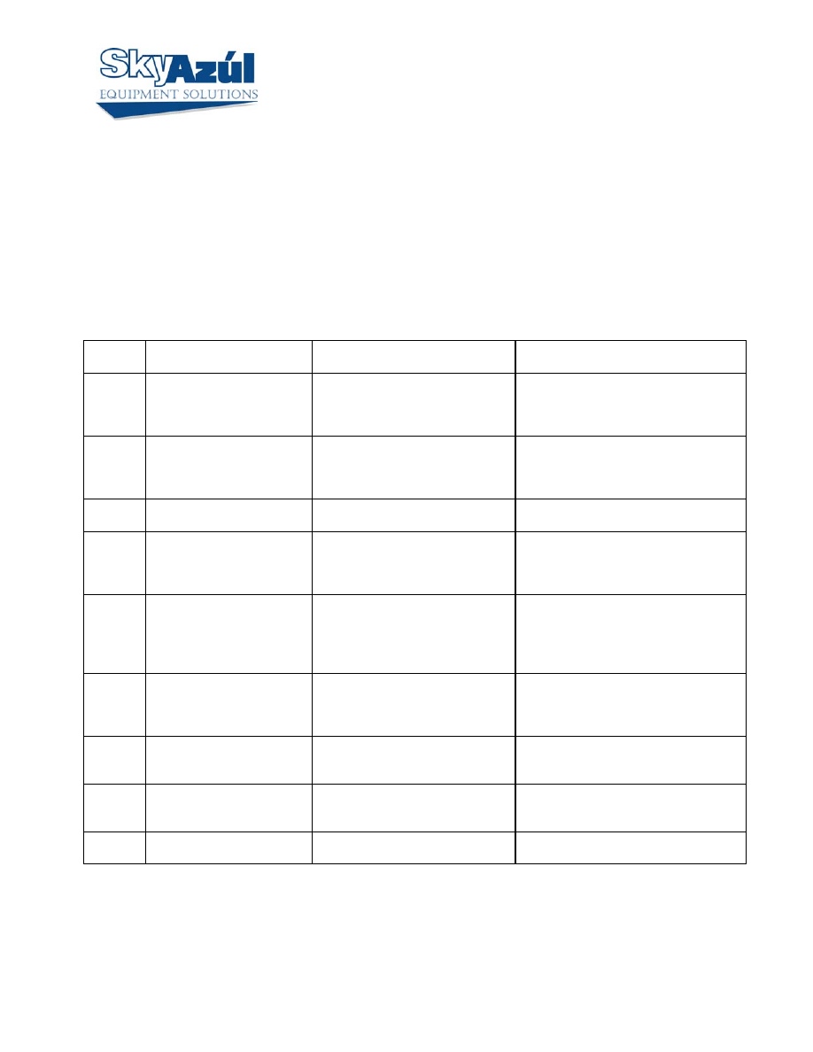
ERROR CODE TABLE
ERROR
CODE
ERROR CAUSE
ACTION
E01
Minimum radius or
maximum angle range
exceeded
Fallen below the minimum radius
or above the angle given in the
load chart due to raising the boom
to far.
Lower boom back to a radius or angle
given in the load chart.
E02
Maximum radius or
minimum angle range
exceeded
The maximum radius or minimum
angle given in the load chart was
exceeded due to lowering the
boom too far.
Raise boom back to a radius or angle
given in the load chart.
E03
Prohibited slewing range
(no load area)
Slewing range prohibited with
load.
Slew back into admissible range.
E04
Operating mode not
available
Operating mode switch in the
console set incorrectly. Operating
mode is not permissible with actual
crane configuration.
Set operating mode switch correctly to
the code assigned to the operating mode
of the crane.
E05
Length range not permitted
Boom has been extended too far or
not far enough. Length sensor
adjustment changed; i.e. length
sensor cable slid off the cable
drum.
Refer to Section 3.7.
Retract or extend boom to correct length
given in the load chart.
E06
Fallen below angle range
with luffing jib operation.
Fallen below the minimum jib
angle specified n the respective
load chart due to luffing out the jib
too far.
Luff in the jib to a radius or angle
specified in the load chart.
E07
No acknowledgment signal
from overload relay (K1).
Overload relay is stuck, defective
or not being selected.
Replace main board in central unit.
Refer to Drawing 4 and Procedure 3 in
Section 5.3
E08
No acknowledgment signal
from Anti-Two-Block
switch relay (K2).
Anti-Two-Block switch relay is
defective or not being selected.
Replace main board in central unit.
Refer to Drawing 4, Section 4.4, and
Procedure 3 in Section 5.3.
E10
Error in length
measurement
With the boom fully retracted, the
length differs by more than 2%.
Refer to Section 3.7.

DS-350 Graphic Modular GM Service Info SKYAZÚL RESOURCES
Page 2
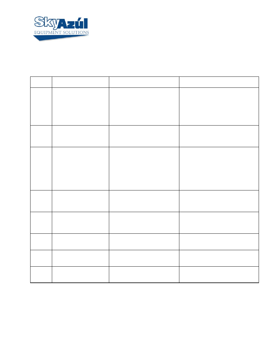
ERROR
CODE
ERROR CAUSE
ACTION
E11
Fallen below limit for the
measuring channel
“length”.
a.) Cable between length sensor
and central unit defective, not
connected or water in the
connectors.
b.)Length sensor Potentiometer
defective.
c.)Electronic board in the
measuring channel defective.
Refer to Section 3.7
a.)Check cable and connector
b.) Check and reset length sensor
Potentiometer. Refer to Procedure 5.
c.) Check signal on main board and
analog input module.
E12
Fallen below lower limit
value for the measuring
channel “pressure
transducer piston side”.
a.) Cable leading from the central
unit to the pressure transducer
defective, loose or water in the
connector.
b.)Pressure transducer on piston
side defective.
c.)Electronic component in the
measuring channel defective.
Refer to Section 3.9
a.)Check cable and connector
b.)Check pressure transducer and reset
pressure channel.
c.) Check signal on main board and
analog input module.
E13
Fallen below lower limit
value for the measuring
channel “pressure
transducer rod side”.
a.)Cable leading from the central
unit to the pressure transducer
defective, loose or water in the
connector.
b.)Pressure transducer on rod side
defective.
c.)Electronic component in the
measuring channel defective.
Refer to Section 3.9
a.)Check cable and connector
b.) Check pressure transducer and reset
pressure channel.
c.) Check signal on main board and
analog input module.
E14
Fallen below lower limit
value for the measuring
channel “force”.
a.)Cable leading from the central
unit to the pressure transducer
defective, loose or water in the
connector. b.)Force transducer
defective. c.)Electronic component
in the measuring channel defective.
a.) Check cable and connectors as well
and replace, if necessary.
b.)Check force transducer.
c.) Check signal on main board and
analog input module.
E 15
Fallen below lower limit
value for the measuring
channel “angle main
boom”.
a.)Cable from central unit to the
length/angle sensor defective or
loose.
b.)Angle sensor defective.
c.)Electronic component in the
measuring channel defective.
Refer to Section 3.8
a.) Check cable.
b.) Check angle sensor and reset
adjustment. Refer to Procedure 5
c.) Check signal on main board and
analog input module.

DS-350 Graphic Modular GM Service Info SKYAZÚL RESOURCES
Page 3
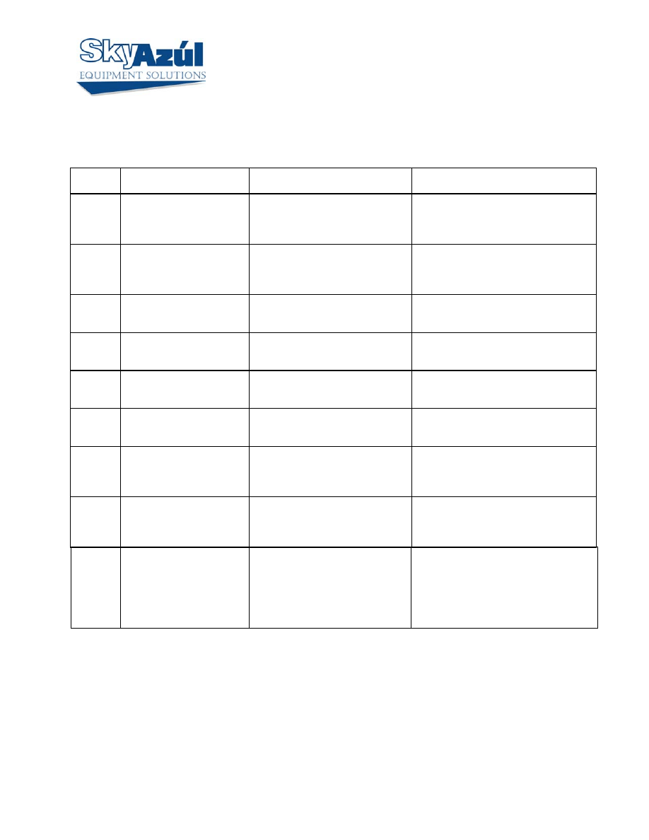
ERROR
CODE
ERROR CAUSE
ACTION
E16
Fallen below lower limit
value for measuring channel
“Luffing Jib Angle”.
a.)Cable from central unit to angle
sensor defective or disconnected or
water inside the plug.
b.)Angle sensor defective.
c.)Electronic component in the
measuring channel defective.
a.) Check cable.
b.) Check angle sensor and reset
adjustment.
c.) Check signal on main board and
analog input module.
E17
Fallen below lower limit
value for the measuring
channel 7.
a.)Cable leading from the central
unit to the sensor of channel 7
defective, loose or water in the
connectors.
b.)Sensor of channel 7 defective.
c.)Electronic component in the
measuring channel 7 defective.
a.) Check cable and connectors.
b.) Check sensor of channel 7 and reset
adjustment.
c.) Check signal on main board and
analog input module.
E18
Outrigger overloaded
Front outrigger overloaded
Check outrigger sensor
E19
Error in the reference
voltage.
Electronic component on the main
board defective.
Replace main board. Refer to Drawing 4
and Procedure 3.
E1A
E1B
Below limiting value for
slewing angle 1.
Below limiting value for
slewing angle 2.
a.)Cable from central unit to the
slewing angle sensor defective or
loose.
b.)Slewing angle potentiometer
defective.
c.)Electronic component in the
measuring channel defective on
main board.
a.) Check cable.
b.) Check and reset slewing angle
potentiometer.
c.) Check signal on main board and
analog input module.
E21
Upper limiting value for the
measuring channel “length”
exceeded.
a.)Cable from central unit to the
length/angle sensor defective or
loose.
b.)Length potentiometer defective.
c.)Electronic component in the
measuring channel defective on
main board.
Refer to Section 3.7
a.) Check cable and connector
b.) Check and reset length sensor
Potentiometer. Refer to Procedure 5.
c.) Check signal on main board and
analog input module.

DS-350 Graphic Modular GM Service Info SKYAZÚL RESOURCES
Page 4
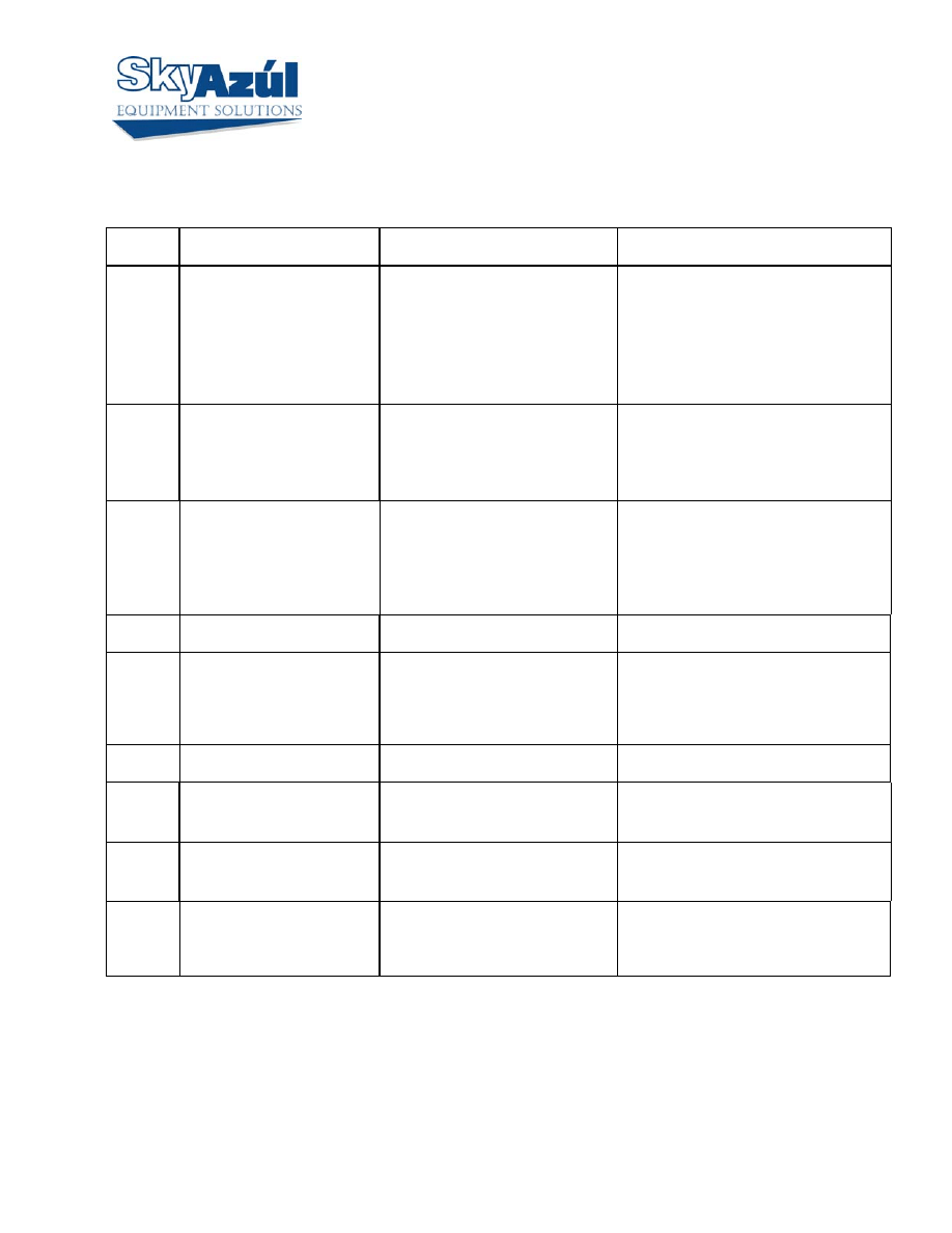
ERROR
CODE
ERROR CAUSE
ACTION
E22
Upper limiting value for the
measuring channel
“pressure piston side”
exceeded.
a.)Cable from central unit to the
pressure transducer defective,
loose or water in the plug.
b.)Pressure transducer on piston
side defective.
c.)Electronic component in the
measuring channel defective on
main board.
Refer to Section 3.9
a.) Check cable and connector
b.) Check pressure transducer and reset
pressure channel.
c.) Check signal on main board and
analog input module.
E23
Upper limit value for the
measuring channel
“pressure transducer rod
side” exceeded.
a.) Cable lead in from the central
unit to press trans defective, not
connected or water in the
connectors.
b.) Pressure transducer on rod side
defective.
c.) Electronic component in the
measuring channel defective.
Refer to Section 3.9
a.) Check cable and connector
b.) Check pressure transducer and reset
pressure channel.
c.) Check signal on main board and
analog input module.
E24
Upper limit value for the
measuring channel “force”
exceeded.
a.) Cable leading from the central
unit to the force transducer
defective, not connected or water
in the connectors.
b.) Force transducer defective.
c.) Electric component in the
measuring channel defective.
a.) Check cable and connectors as well
and replace, if necessary. b.) Check
force transducer.
c.) Check signal on main board and
analog input module.
E25
Upper limit value for the
measuring channel “angle
main boom” exceeded.
a.) Cable leading from the central
unit to the length/angle sensor
defective, loose or water in the
connectors.
b.) Angle sensor defective
c.) Electronic component in the
measuring channel defective.
Refer to Section 3.8
a.) Check cable.
b.) Check angle sensor and reset
adjustment. Refer to Procedure 5
c.) Check signal on main board and
analog input module.
E26
Upper limit value for the
measuring channel “Luffing
Jib Angle” exceeded.
a.) Cable leading from the central
unit to the jib angle sensor
defective, loose or water in the
connectors.
b.) Jib angle sensor defective. c.)
Electronic component in the
measuring channel defective.
a.) Check cable.
b.) Check angle sensor and reset
adjustment.
c.) Check signal on main board and
analog input module.
DS-350 Graphic Modular GM Service Info SKYAZÚL RESOURCES
Page 5
ERROR
CODE
ERROR CAUSE
ACTION
E27
Upper limit value for the
measuring channel 7
exceeded.
a.) Cable leading from the central
unit to the sensor of channel 7
defective, loose or water in the
connectors.
b.) Sensor of channel 7 defective.
c.) Electronic component in the
measuring channel 7 defective.
a.) Check cable and connectors.
b.) Check sensor of channel 7 and reset
adjustment.
c.) Check signal on main board and
analog input module.
E29 Reference
voltage
defective.
a.) The total of the supply and the
reference voltages on MP10 is
more than 3.3V
b.) A/D converter defective.
a.) Check supply voltages.
b.) Replace main board or analog input
module. Refer to Drawing 4 and
Procedure 3 Steps 1,2,4, 11,12..
E2A
E2B
Above limiting value for
slewing angle 1.
Above limiting value for
slewing angle 2.
a.)Cable from central unit to the
slewing angle sensor defective or
loose.
b.)Slewing angle potentiometer
defective.
c.)Electronic component in the
measuring channel defective on
main board.
a.) Check cable.
b.) Check and reset slewing angle
potentiometer.
c.) Check signal on main board and
analog input module.
E31
Error in the system
program.
a.) EPROM with system program
defective.
b.) Electronic component on the
main board defective.
a.) Replace system program EPROM
b.) Check signal on main board and
analog input module.
E37
Error in the program run
a.) EPROM with system program
defective.
b.) Electronic component on the
main board defective.
a.) Replace system program EPROM.
b.) Check signal on main board and
analog input module.
E38
System program and Data
EPROM do not match.
The system program in the LMI
does not correspond to the
programming in the data EPROM
Replace system program EPROM or
Data EPROM. Refer to Procedure 2
E39
System program and TLK
EPROM do not match.
The system program in the LMI
does not correspond to the
programming in the data EPROM
Replace system program EPROM or
TLK EPROM. Refer to Procedure 2
E41
Error in the external RAM.
Defective electronic component.
Replace main board or analog input
module. Refer to Drawing 4 and
Procedure 3, Steps 1,2,4, 11, and 12.
DS-350 Graphic Modular GM Service Info SKYAZÚL RESOURCES
Page 6
ERROR
CODE
ERROR CAUSE
ACTION
E42
Error in the external
write/read memory
(RAM). Part 1
Internal defect in digital part of
CPU.
Exchange write/read memory (CMOS-
RAM). Replace CPU module. Refer to
Drawing 4 and Procedure 3, Steps 1-3,
13,14.
E43
Error in the external
write/read memory
(RAM). Part 2.
Internal defect in digital part of
CPU.
Exchange write/read memory (CMOS-
RAM). Replace CPU module. Refer to
Drawing 4 and Procedure 3, Steps 1-3,
13,14.
E45
Redundancy error in A/D
conversion.
Defective electronic component.
Replace analog input module. Refer to
Drawing 4 and Procedure 3, Steps 1,2,4,
11,12.
E46
Error in A/D conversion.
Defective electronic component.
Replace analog input module. Refer to
Drawing 4 and Procedure 3 Steps 1,2,4,
11,12.
E47
Malfunction in the
monitored write/read
memory.
Internal defect in digital part of
CPU
Replace CPU module. Refer to Drawing
4 and Procedure 3 Steps 1-3, 13,14
E48
Cyclic RAM test: Error in
the internal write/read
memory.
Internal defect in digital part of
CPU
Replace CPU module. Refer to Drawing
4 and Procedure 3 Steps 1-3, 13,14
E51
Error in data EPROM.
EPROM Module not bridged
correctly
Data EPROM on the main board
defective.
Replace Data EPROM. Make sure BR3
on the main board is installed. Refer to
Procedure 2.
E52
Error in load chart
EPROM.
EPROM Module not bridged
correctly
Data EPROM on the main board
defective.
Replace EPROM Module and reset
pressure channels. Refer to Drawing 4
and Procedure 4.
E56
Error in crane data
EEPROM.
emory module wrongly
bridged.
rane data EEPROM defective
idge memory module acc. To
memory type
eplace crane data EEPROM
Replace EPROM Module and
reset pressure channels. Refer to
Drawing 4 and Procedure 4.
DS-350 Graphic Modular GM Service Info SKYAZÚL RESOURCES
Page 7
ERROR
CODE
ERROR CAUSE
ACTION
E57
Error in serial crane data
EEPROM.
erial crane data EEPROM
does not contain valid data.
emory module defective
rite data on the serial crane data
EEPROM (by means of test
program or on-line function), then
restart the LMI
eplace EPROM Module and reset
pressure channels. Refer to
Drawing 4 and Procedure 4.
E58
Error in the serial analog data
EEPROM.
o valid data in the serial analog
data EEPROM.
MI main board defective.
rite data on the serial analog data
EEPROM by means of the test
program, then, restart the LMI
eplace LMI main board.
E69
Error in the load chart
EPROM
emory module wrongly bridged idge memory module acc. to
memory type
The number of the selected
EPROM base and the
programmed value are not
identical
oad chart EPROM defective
eplace load chart EPROM
E70
Error in digital output
module.
Central unit unable to correspond
with digital output module.
a.) Check supply voltage.
b.) Replace digital output module.
E71 Incorrect
acknowledgment
of the 1. Relay on the main
board.
a.) Anti Two-block relay is stuck
or defective.
b.) Anti Two-Block relay is not
being selected due to a break on
the main board.
Replace main board. Refer to Drawing 4
and Procedure 3.
E72 –
E77
Analogous to E71 for the
relays 2...7.
Analogous to E71 for the relays
2...7.
Analogous to E71 for the relays 2..7.
E84
Wrong rigging condition.
he selected rigging condition is
not contained in the data
EPROM.
elect another rigging condition
heck the programming in the data
EPROM.
E85
Error in the radius
determination
he computed radius is too
small (negative deflection)
heck the programming in the data
EPROM.
E89
Change of the operating
code during lifting a load.
The operating mode switch in the
console was used during lifting a
load.
Lower the load and set the operating
mode switch correctly to the code
assigned to the actual operating mode of
the crane.

DS-350 Graphic Modular GM Service Info SKYAZÚL RESOURCES
Page 8
ERROR
CODE
ERROR CAUSE
ACTION
E 91
No data transmission from
console to central unit.
(Refer to Section 9)
a.)24V supply of console
interrupted.
b.)Interruption or accidental
ground in the line from console
electronics to central unit.
c.)Transmitter/receiver module
defective.
a.) Check 24V at terminal X1 of console
electronics.
b.) Check the connection between
console electronics and central unit.
c.) If accidental ground occurs, the
transmitter module in the console
electronics can be damaged. Replace the
console electronics or main board
respectively.
E92
Error in the data
transmission from console
to central unit. (Refer to
also Section 3.10)
a.) Temporary interruption of the
data line from console electronics
to central unit. b.)
Transmitter/receiver module
defective.
a.) Check the connection between
console electronics and central unit.
E93
Error in the data
transmission from central
unit to console. (Refer to
also Section 3.10)
a.) Temporary interruption of the
data line from console electronics
to central unit. b.)
Transmitter/receiver module
defective.
Refer to Section 3.10.
a.) Check the connection between
console electronics and central unit.
b.) Replace console electronics or main
board respectively.
E94
No data transmission for
central unit to console.
(Refer to also Section 3.10)
a.) Interruption or accidental
ground in the line from console
electronics to central unit.
b.) Transmitter/receiver module
defective.
c.) Data-EPROM defective.
d.) CPU defective.
e.) Electromagnetic interference
(when switching contractors or
valves)
Refer to Section 3.10.
a.) Check the connection between
console electronics and central unit. If
you find an accidental ground, the
transmitter module in the console
electronics can be damaged. Replace
the console electronics.
b.) Replace console electronics or main
board respectively. c.)Check data
EPROM.
d.) Replace CPU module. Refer to
Drawing 4 and Procedure 3 Steps 1-3,
13,14.
e.) Eliminate interference source by
inverse diodes or varistors.

DS-350 Graphic Modular GM Service Info SKYAZÚL RESOURCES
Page 9
ERROR
CODE
ERROR CAUSE
ACTION
E95
Error in the crane data
EPROM
a.) Data EPROM defective
b.) Position of jumper for the
selection of the type of EPROM is
wrong
c.) Electronics component on the
main board defective.
a.) Replace data EPROM
b.) Check the jumper position
c.) Replace CPU module. Refer to
Drawing 4 and Procedure 3 Steps 1-3,
13,14
E96
Error in the internal RAM
of the CPU of the console
CPU or main board of the console
defective
Replace CPU module. Refer to Drawing
4 and Procedure 3 Steps 1-3, 13,14
E97
Error in the external RAM
of the CPU of the console
a.) External RAM of the console
defective
b.) Electronic component on the
main board defective.
a.) Replace console main board
b.) Replace console main board Refer to
Drawing 5.
E98
Wrong jumper position in the
console
a.) The jumper position BR 9/BR
10 in the console does not
correspond to the actual type of
central unit.
b.) Electronic component on the
main board defective.
a.) Check the jumper position
b.) Replace console main board Refer
to Drawing 5.
EAB
Short circuit in the A2B
switch circuit
hort circuit in the A2B switch
hort circuit in the cable to the
A2B switch
ectronic component on the
analog input module
defective.
efer to Section 3.6.
eplace A2B switch
eplace cable to the A2B switch
heck analog input module.
Replace if necessary., Refer to
Drawing 4 and Procedure 3
Steps 1,2,4, 11,12.
DS-350 Graphic Modular GM Service Info SKYAZÚL RESOURCES
Page 10
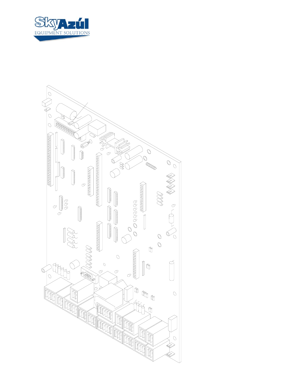
CENTRAL UNIT MAIN BOARD LAYOUT
BOARD P/N
024-352-300-001
MP1 = KGND
MP4 = +5V
MP8 = +9V
MP9 = +6V
MP24 -= +BATT
MP25 -= +UBS console, sensors,
DI’s
MP26 -= GND
MP29 -= +5V hand terminal
LED’S
H08 - LOAD
H09 - A2B
H10 - MAIN IN/OUT
H11 - POWER
H12 - TxD
HYDRAULIC LINES.
36
54
X1
9
52
62
7776
69
60
MP1
MP25
1
MP4
MP9
MP8
MP26
MP24
35 34 33
31
32
27
28
29
30
26
23
24
25
20
21
22
15
17
18
19
16
11
12
13
10
14
51
53
59 58 57
61
65
66
67
68
64
87
6 5 4
2 1
3
DI6
THRU
DI1
H8
H9
H11
H10
H12
K10

DS-350 Graphic Modular GM Service Info SKYAZÚL RESOURCES
Page 11
PRESSURE TRANSDUCER ZERO ADJUSTMENT PROCEDURE
USING GRAPHIC CONSOLE FOR ZERO-SETTING OF PRESSURE
TRANSDUCER & FORCE INPUTS
The zero setting consists of defining zero-point offset. The zero point offset is added to the transducer
measurement to calculate the real physical pressure or force.
To define the zero-point offset the pressure transducer or force sensor must be in equilibrium (no load
condition). Therefore the boom must be lowered all the way down (no rest pressure) and the hydraulic
hoses disconnected from the pressure transducers.
CAUTION: Ensure there is no pressure in the hydraulic line when disconnecting the hoses from
pressure transducers.
ACTIVATING THE ZERO-SETTING FUNCTION
To activate the zero-setting Function, press the INFO key on the console to activate the INFO Function.
Now press the CTRL key. At this point, a five digit Authorization Number must be entered. Only
authorized personnel may adjust the zero-point settings.
Example: 6 4 3 5 6
ZERO-SETTING THE TRANSDUCER INPUTS
Now, having successfully entered a valid password, the piston-side zero-point setting function is
activated.
The display shows which transducer (piston-side, rod-side or force) is being zeroed and a horizontal
dial marks the present pressure (or force) difference in %. By pressing the + key, the input pressure (or
force) is adjusted upwards, and by pressing the minus (-)key, the input value is adjusted downwards.
When the plus (+) and minus (-) keys are pressed simultaneously, the zero setting occurs
automatically. Manual adjustments may be preformed using + or -.
The return key toggles between the piston-side, the rod-side, and the force zero-setting.
When the operator is finished, pressing the EXC or INFO key returns the console display to normal.
Wyszukiwarka
Podobne podstrony:
PAT DS 350 G & GW Service Data
PAT DS 350 G & GW Service Data
PAT DS 160 Service Data
ENGINE MECHANICAL Service data
ENG DS 1 1414305 0 DATA SHEET 1
Prezentacja firmy MARSTATE SERVICE BHP PPOZ PPT
PaT eczki G( ), niefermentujT ce
Gatunki dziennikarskie licencjat PAT czesc 2
CW2006EX Mill Turn data sheet web
hplj 5p 6p service manual vhnlwmi5rxab6ao6bivsrdhllvztpnnomgxi2ma vhnlwmi5rxab6ao6bivsrdhllvztpnnomg
3 Data Plotting Using Tables to Post Process Results
An%20Analysis%20of%20the%20Data%20Obtained%20from%20Ventilat
233511 DS
więcej podobnych podstron