The
µ-counter, a PIC based programmable frequency meter
Project Overview
This project proposes a simple frequency reader specifically designed for QRP rigs, also if you may
employ it also as a workbench instrument. In fact it exhibits several very interesting features, like a
maximum working frequency above 40 MHz, a 10 Hz resolution, a low consumption (15 mA) and a
very simple assembly. Moreover it is possible to program an IF value and mode simply by means of
two push buttons.
The basic idea comes from the AN592 Microchip application note: "Frequency counter using
PIC16C5x"
(1)
, where you may find a simple software wich implements a frequency counter using a
PIC microcontroller. I read also a couple of interesting articles concerning this matter on "QST"
(2)
,
and so I was encouraged to go ahead with the project. I wrote a specifically designed software to
improve the counter resolution, to handle the IF mode and value by means of an operating menu, to
decode and edit the read frequency on an LCD display. The result was a simple and effective
device, equipped with a free software available to those who could be interested.
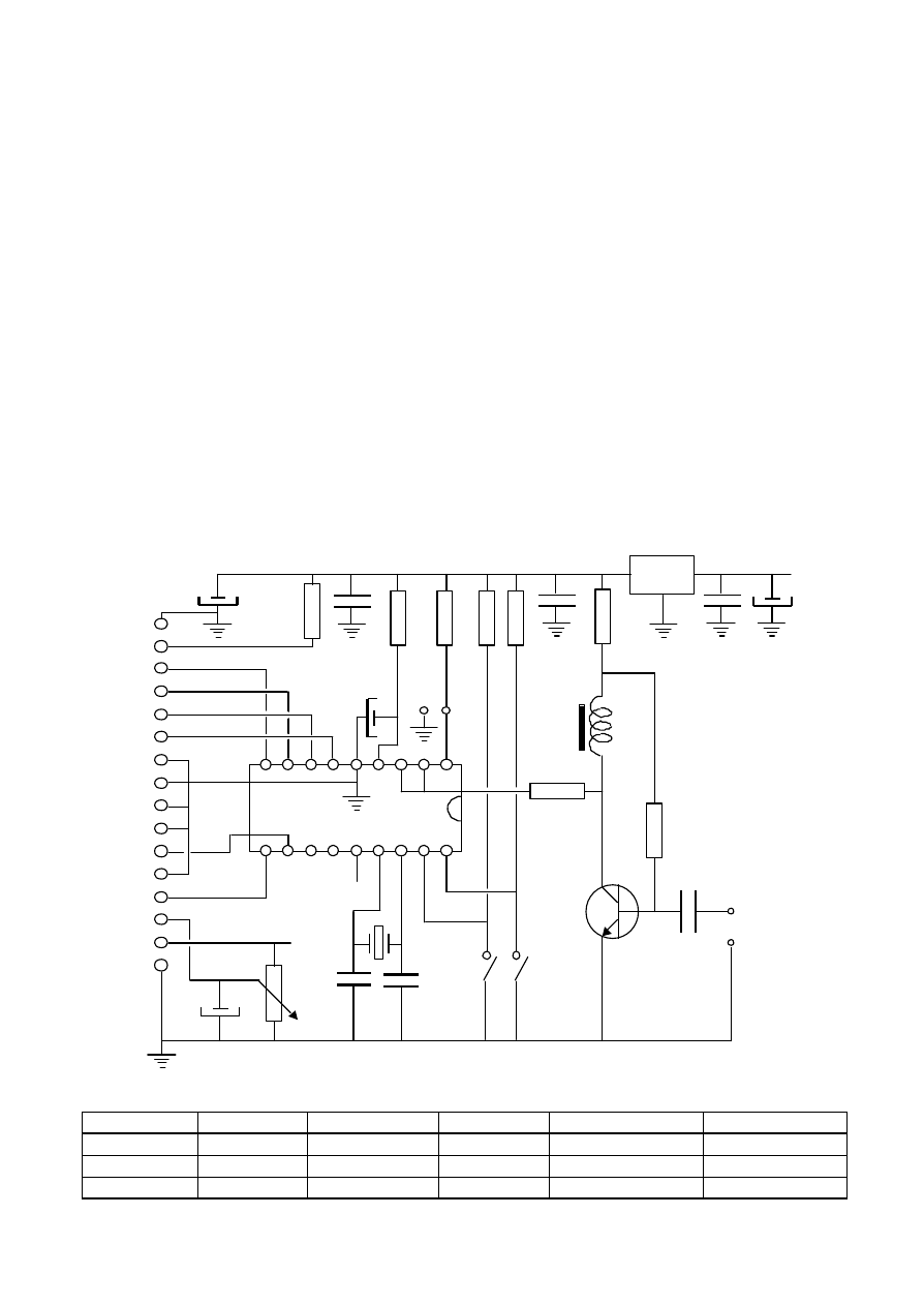
The electrical schematic
R1 : 22
Ω
R5 : 18 K
Ω
R9 : 10 K
Ω
var.
C4 : 100 nF
C8 : 33 pF
U2 : 78L05 see text
R2 : 22 K
Ω
R6 : 470
Ω
C1 : 10
µ
F
C5 : 10
µ
F
C9 : 33 pF see text
T1 : 2N2369
R3 : 18 K
Ω
R7 : 470
Ω
C2 : 100 nF
C6 : 1
µ
F
C10 : 10 nF
L1 : 10
µ
H
R4 : 18 K
Ω
R8 : 10 K
Ω
C3 : 100 nF
C7 : 4.7
µ
F
U1 : PIC16F84
input
+ 5 V
12 V
SET
>
+ 5 V
U1
PIC16F84
T1
2N2369
C1
C2
C6
C7
C8
C9
XTAL
C10
C3
R2
R6
R7
R8
R9
U2
78L05
R3
DB7
DB6
DB5
DB3
DB2
DB1
DB0
E
R/W
RS
Vo
Vdd
Vss
DB4
LD+
LD-
C4
R1
R4
R5
L1
JP
C5

The electrical schematic is very simple, given that most of the functions are implemented by the
microprocessor. It was needed only an amplifier stage to raise the input signal level from 200-300
mV p.p. to about 3 volts p.p., so as to drive correctly the RA4 (pin 3) triggered gate of the PIC. I
implemented a common emitter amplifier using a 2N2369 transistor, with a small inductance series
connected to the collector load, so as to improve the frequency response at the high frequencies. So
it was obtained a suitable gain from 100 KHz up to about 50 MHz, the lower limit being forced only
by the C10 capacitor. The R8 value is chosen so as to obtain about 1,6-1,8 V on the transistor
collector, such a value is necessary to drive correctly the PIC gate, and you may verify this voltage
after completing the assembly, and before inserting the PIC on its socket.
The time base is provided from a 4 MHz, parallel resonant, microprocessor crystal, if you have at
your disposal a professiona l frequency meter, you may tune accurately the frequency by adjusting
the value of C9, which could also be replaced by a little plastic trimmer, otherwise the reading will
be in any case within the quartz tolerance (typically 50 p.p.m. max).
The 78L05 regulator is well suited to feed the 15 mA required, however if you want to employ a
back-lighted LCD module, it will be necessary to replace it with a 7805 model, capable to supply
about 60 mA without excessive heating. On the 16 pin connector two pins are provided (15, 16) to
drive the LCD LED panel. The supply voltage should be in the 8-12 volts range, and you may
control the display brightness by turning the R9 trimmer, the maximum value being obtained with
the cursor completely turned toward the ground.
The Software Functions
The counter works using the 8 bits internal counter (TMR0) and the 8 bits prescaler of the PIC. The
prescaler cannot be read directly by means of the PIC basic instructions, therefore it is necessary to
employ a trick in the software, the whole process is well described in the Microchip application
note
(1)
where you may find further details. To improve the resolution I managed a third 8 bits
counter, which is increased by the program when a timer overflow is detected. So it was possible to
improve the overall counters capacity to 24 bits. The counting period is obtained by means of some
accurate delay routines, tuned precisely using my workbench instrumentation.
Several readings / second are implemented, so as to simulate a continuous display refresh.
The counter programming is obtained using two push buttons SET and ">" in the following
manner :
-
Pressing the SET button a first time, the IF value will be displayed ("IFset" function) and the
flashing cursor is positioned on the first digit you may modify (ten MHz), now you may modify
the digit value by means of the ">"
push button in the 0 - 9 range. After changing this digit
you may go to the next digit by pressing again the SET button, and so on until you reach the last
digit to the right.
-
Another pressing of the SET button starts the "Mode set" function, and now you may choose,
by means of ">" button, between the three operating modes : "VFO + IF", "IF - VFO", "VFO -
IF".
-
Now a new SET button pressing enters the "Prescaler" setting mode allowing, by means of
">" button, to select one of the provided ratios (see below)
-
A last SET button pressure closes the menu, saves the setting parameters in the PIC EEPROM,
and re-activate the frequency reading function.
Keep in mind that, when operating in the "IF - VFO" or "VFO - IF" modes, the frequency value will
be displayed only if the result of the subtraction is positive.
By inserting the JP jumper the
µ
-counter may be connected to a prescaler, so as to enhance the
frequency reading range up to 1.5 GHz.
The following settings may be chosen :
prescaler ratio
Max frequency
resolution
Readings/sec
10
500 MHz
100 Hz
9
32
1.5 GHz
100 Hz
3
64
1.5 GHz
200 Hz
3
128
1.5 GHz
400 Hz
3
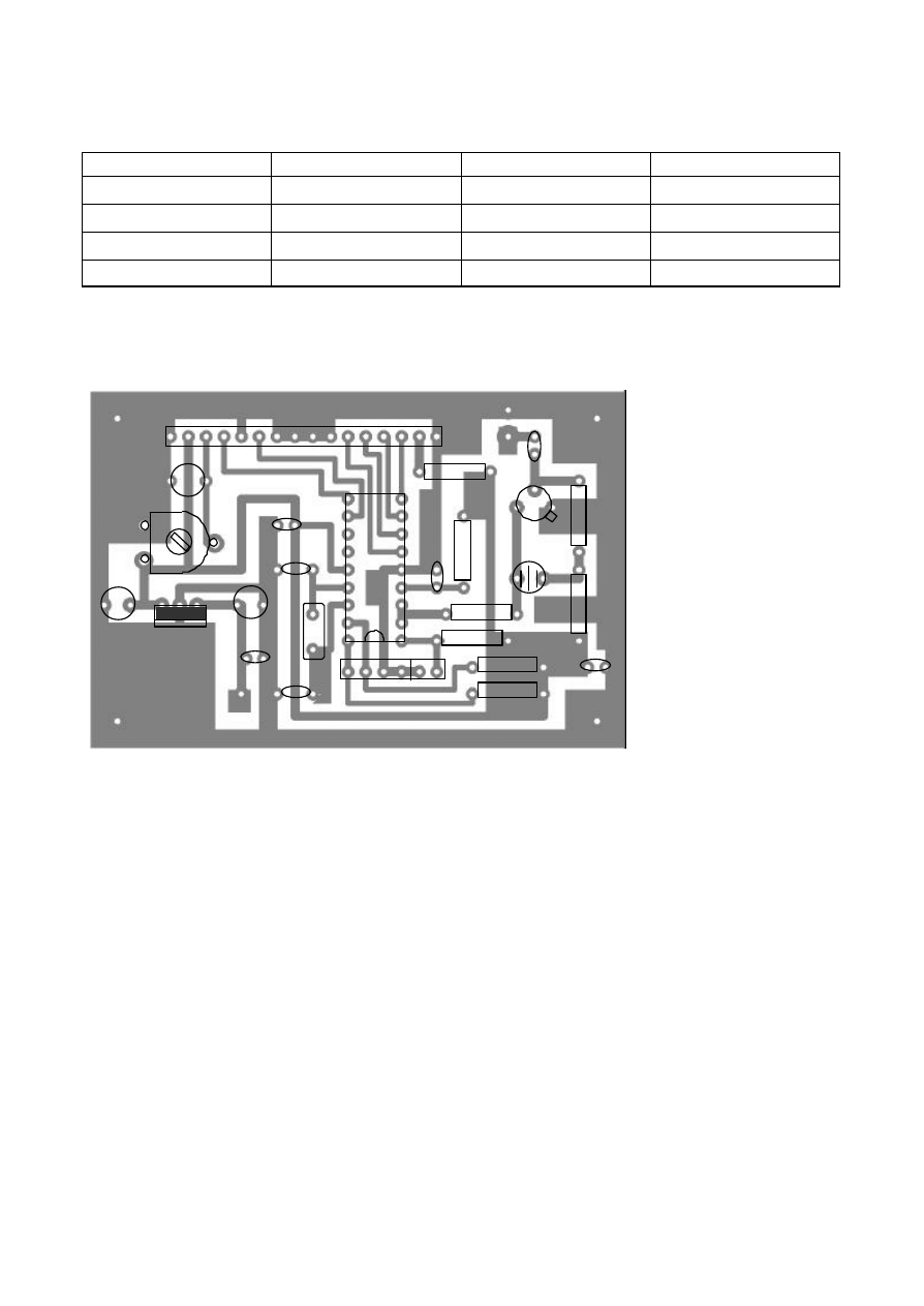
The device assembly
The assembly is done on a single sided PC board measuring 76 x 51 mm. On the board are placed
also a female 16 pin connector, 2.5 mm spacing, to match the LCD module and a male 6 pin
connector to link the two push buttons and the JP jumper. The components placement is shown
clearly in the picture, and the assembly is very simple, due also to the small number of parts.
The LCD module may be connected using a 14 wires flat cable (16 wires if back- lighted) or it may
be inserted directly on the connector, as shown in the photo. In this case, a male connector must be
soldered on the LCD, choosing a "long size" pin model, so as to leave some free space under the
module, while the 7805 regulator will be folded against the board. I recommend to employ small
sized components, like multi layer ceramic and tantalum capacitors, which will fit better to the PCB
size, using a 7805 regulator if a back-lighted LCD is employed.
The PIC microprocessor must be inserted on a 18 pin socket, so it will be possible to extract it if
some software upgrade should be needed.
Vss
Vdd
Vo
RS
R/W
E
DB0
DB1
DB2
DB3
DB4
DB5
DB6
DB7
LD+
LD-
+
+
C5
C4
U2
U1
R9
C7
C8
C9
XTAL
C2
R2
C6
R4
R5
>
SET
JP
R7
R3
T1
L1
R8
C3
R6
C10
input
+12
R1
+
C1

The 1:1 scale PCB (76x51 mm)
The 1:1 PCB may be reproduced in several ways. I suggest to copy it on a transparent using a good
quality laser photocopier, or by means of a scanner and an inkjet printer. Next you may employ a
usual photo etching technique. I may provide the master in CIRCAD format to those who are
interested.
Conclusions
I built several units of this device, and it always proved to be very effective and easy to assemble.
By tuning accurately the oscillator, it is also possible to use it as a workbench instrument, also if it
was thought mainly as a QRP complement. The power consumption is very low (about 15 mA
without back-light), so you may use a common 9 V radio battery to feed it. I may provide the
software, the CIRCAD master and also the programmed PIC to those who are interested in the
project.
You may contact me for any question, writing to my E- mail address :
francesco_morgantini@libero.it
or visiting my WEB site :
www.qsl.net/ik3oil
.
Notes
(1)
- See the AN592 application note at the WEB address :
http://www.microchip.com/1010/suppdoc/appnote/all/an592/index.htm
(2)
- A PIC based Digital Frequency Display, by Neil Heckt, QST, May 1997
- The Unicounter, a multipurpose frequency counter/electronic dial, by Ron Stone KA3J,
QST, Dec 2000
Wyszukiwarka
Podobne podstrony:
2003 Is coming to an Eng 2003 Zbliża się do inż
Eurocode 4 Part1 2 (ENG) prEN 1994 1 2 (2003 Mai)
docu betz 2003 eng webversie
Eurocode 3 Part1 5 (ENG) prEN 1993 1 5 (2003 Set)
ostre stany w alergologii wyklad 2003
Brasil Política de 1930 A 2003
Technologia spawania stali wysokostopowych 97 2003
chrystus jest zyciem mym ENG
Pirymidyny 2003
KONSERWANTY 2003
Nawigacja fragmenty wykładu 4 ( PP 2003 )
WYKŁAD 2 prawa obwodowe i rozwiązywanie obwodów 2003
ISM Code 97 2003
obiektywne metody oceny postawy ciała (win 1997 2003)
więcej podobnych podstron