9
B7A Link Remote I/O Components Overview
Parts Summary and Configuration Guide to Build a Wire-Saving B7A Link
Remote I/O System
1
Just two wires transmit data, simplifies
installation and troubleshooting
1
High-speed (100 m max. at 3 ms) and
long distance (500 m max. at 19.2 ms)
configurations available
1
Wide range of transistor and relay
blocks to meet application needs
Ordering Information
3
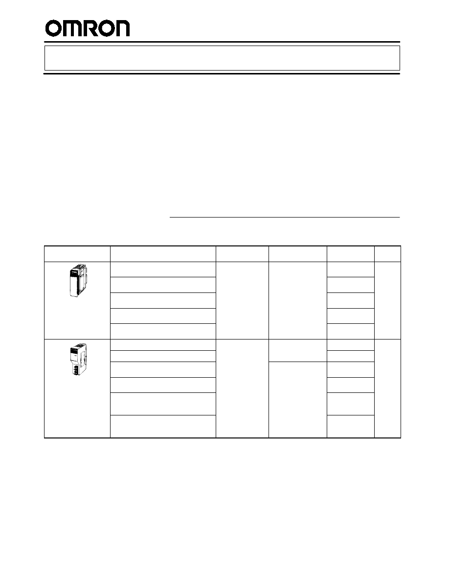
PLC MASTER LINK MODULES
Appearance
I/O classification
I/O configuration
System
compatibility
Part number
Stan-
dards
16-point output, long distance and
high-speed systems
Use B7A/B7AS
input and output
i
l
CQM1 compact
PLCs
CQM1-B7A02
UL
CSA
CE
32-point output, long distance and
high-speed systems
in ut and out ut
terminals
PLCs
CQM1-B7A03
CSA
CE
(See
Note)
16-point input, long distance and
high-speed systems
CQM1-B7A12
Note)
32-point input, long distance and
high-speed systems
CQM1-B7A13
16-point input/16-point output, long
distance and high-speed systems
CQM1-B7A21
16-point input, long distance system
Use B7A/B7AS
input and output
CS1, C200H Alpha
and C200HS PLCs
C200H-B7AI1
UL
CSA
16-point output, long distance system
input and output
terminals
and C200HS PLCs,
Special I/O
C200H-B7AO1
CSA
CE
(S
32-point output, long distance and
high-speed systems
CS1, C200H Alpha
and C200HS PLCs,
G
2 S
i l I/O
C200H-B7A02
(See
Note)
32-point input, long distance and
high-speed systems
and C200HS PLCs,
Group-2 Special I/O
C200H-B7A12
Mixed I/O, 16-point input/
16-point output; long distance and
high-speed systems
C200H-B7A21
Mixed I/O, 32-point input/ 32-point
output; long distance and high-speed
systems
C200H-B7A22
Note: Information on EC Directives
Individual OMRON products that comply with EC Directives conform to the common emission standards of EMC Directives. How-
ever, the emission characteristics of these products installed on customers’ equipment may vary depending on the configuration,
wiring, layout, and other conditions of the control panel used. For this reason, customers are requested to check whether the emis-
sion characteristics of the entire machine or equipment comply with the EMC Directives.
B7A Link Overview
B7A Link Overview
2
3
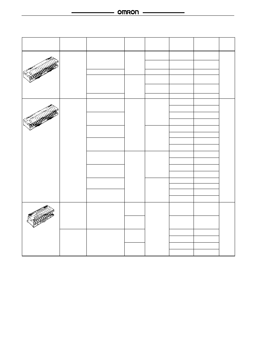
16-POINT TERMINALS
Transistor I/O Link Modules
Appearance
I/O
classification
I/O configuration
I/O delay
(typical)
Internal I/O
common
Error
processing
(See Note 1)
Part number
Stan-
dards
Input,
16 points
NPN compatible
Normal
speed
19 2
-- common
------
B7A-T6A1
(See Note 2)
UL
CSA
CE
s eed
19.2 ms
+/-- common
------
B7A-T6B1
(See Note 2)
CSA
CE
(See
Note 5)
PNP compatible
+/-- common
------
B7A-T6C1
Note 5)
NPN compatible
High
speed
3
-- common
------
B7A-T6A6
(See Note 2)
s eed
3 ms
+/-- common
------
B7A-T6B6
(See Note 2)
PNP compatible
+/-- common
------
B7A-T6C6
Output,
16 points
NPN open collector
100 mA/point
Normal
speed
+ common
HOLD
B7A-R6B11
UL
CSA
16 points
100 mA/point
speed
19.2 ms
LOAD OFF
B7A-R6B31
CSA
CE
(S
NPN open collector
500 mA/point (See
HOLD
B7A-R6C11
(See
Note 5)
500 mA/point (See
Note 3)
LOAD OFF
B7A-R6C31
Note 5)
PNP open collector
100 mA/point
-- common
HOLD
B7A-R6F11
100 mA/point
LOAD OFF
B7A-R6F31
PNP open collector
500 mA/point (See
HOLD
B7A-R6G11
500 mA/point (See
Note 4)
LOAD OFF
B7A-R6G31
NPN open collector
100 mA/point
High
speed
+ common
HOLD
B7A-R6B16
100 mA/point
speed
3 ms
LOAD OFF
B7A-R6B36
NPN open collector
500 mA/point (See
HOLD
B7A-R6C16
500 mA/point (See
Note 3)
LOAD OFF
B7A-R6C36
PNP open collector
100
A/
i t
-- common
HOLD
B7A-R6F16
100 mA/point
LOAD OFF
B7A-R6F36
PNP open collector
500 mA/point (See
HOLD
B7A-R6G16
500 mA/point (See
Note 4)
LOAD OFF
B7A-R6G36
Input.
16 points
NPN compatible
Normal
speed
19.2 ms
+/-- common
------
B7AS-T6B1
UL
CSA
CE
(S
High
speed
3 ms
------
B7AS-T6B6
(See
Note 5)
Output,
16 points
NPN open collector
100 mA/point
Normal
speed
HOLD
B7AS-R6B11
16 points
100 mA/point
speed
19.2 ms
LOAD OFF
B7AS-R6B31
High
speed
HOLD
B7AS-R6B16
speed
3 ms
LOAD OFF
B7AS-R6B36
Note: 1. HOLD:
The previous output condition will be on hold when an error occurs.
LOAD OFF: All outputs will be OFF when an error occurs.
2. The 16-point B7A-T6A
P
and 16-point B7A-T6B
P
are different from each other in terminal configuration.
3. N-channel MOSFET open drain output
4. P-channel MOSFET open drain output
5. Information on EC Directives
Individual OMRON products that comply with EC Directives conform to the common emission standards of EMC Directives.
However, the emission characteristics of these products installed on customers’ equipment may vary depending on the configu-
ration, wiring, layout, and other conditions of the control panel used. For this reason, customers are requested to check whether
the emission characteristics of the entire machine or equipment comply with the EMC Directives.
B7A Link Overview
B7A Link Overview
3
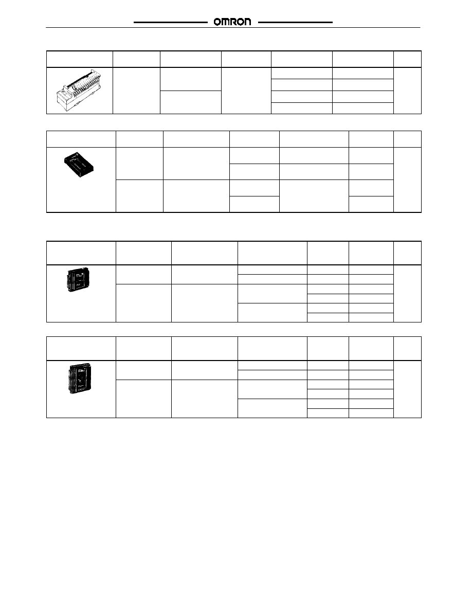
16-point Relay Output Link Modules
Appearance
I/O
classification
I/O configuration
I/O delay
(typical)
Error processing
(See Note 1)
Part number
Stan-
dards
Output,
16 points
Relay outputs
G6D-1A DC24
Normal speed
19 2 ms
HOLD
G70D-R6R11-B7A
UL
CSA
16 points
(SPST-NO)
G6D-1A DC24
19.2 ms
(See Note 2)
LOAD OFF
G70D-R6R31-B7A
CSA
CE
(S
(
)
Power MOSFET
relay outputs
(
)
HOLD
G70D-R6M11-B7A
(See
Note 3)
relay outputs
G3DZ-2R6PL DC24
LOAD OFF
G70D-R6M31-B7A
Note 3)
PCB Models
Appearance
I/O
classification
I/O configuration
I/O delay
(typical)
Error processing
(See Note 1)
Part number
Stan-
dards
Input,
16 points
TTL input
Normal speed
19.2 ms
------
B7A-T6D2
UL
CSA
CE
16 oints
High speed
3 ms
------
B7A-T6D7
CSA
CE
(See
Note 3)
Output,
16 points
NPN open collector
50 mA/point
Normal speed
19.2 ms
HOLD/LOAD OFF
selected by wiring
B7A-R6A52
Note 3)
16 oints
50 mA/ oint
High speed
3 ms
selected by wiring
B7A-R6A57
3
LINK MASTER ADAPTERS FOR HIGH--DENSITY I/O PLC MODULES
16-point Adapters
Appearance
I/O classification
I/O configuration
I/O delay (typical)
Error
processing
(See Note 1)
Part number
Stan-
dards
Input,
16
i t
NPN compatible
Normal speed 19.2 ms
------
B7A-T6E3
UL
CSA
,
16 points
High speed 3 ms
------
B7A-T6E8
CSA
CE
Output,
16
i t
NPN open collector
50
A/
i t
Normal speed 19.2 ms
HOLD
B7A-R6A13
CE
(See
,
16 points
50 mA/point
LOAD OFF
B7A-R6A33
(See
Note 3)
High speed 3 ms
HOLD
B7A-R6A18
LOAD OFF
B7A-R6A38
32-point Adapters
Appearance
I/O classification
I/O configuration
I/O delay (typical)
Error
processing
(See Note 1)
Part number
Stan-
dards
Input,
32
i t
NPN compatible
Normal speed 19.2 ms
------
B7A-T3E3
UL
CSA
,
32 points
High speed 3 ms
------
B7A-T3E8
CSA
CE
Output,
32
i t
NPN open collector
50
A/
i t
Normal speed 19.2 ms
HOLD
B7A-R3A13
CE
(See
,
32 points
50 mA/point
LOAD OFF
B7A-R3A33
(See
Note 3)
High speed 3 ms
HOLD
B7A-R3A18
LOAD OFF
B7A-R3A38
Note: 1. HOLD:
The previous output condition will be on hold when an error results.
LOAD OFF: All outputs will be OFF when an error results.
2. These G70D Relay Output Link Modules cannot be connected to high-speed B7A.
3. Information on EC Directives
Individual OMRON products that comply with EC Directives conform to the common emission standards of EMC Directives.
However, the emission characteristics of these products installed on customers’ equipment may vary depending on the configu-
ration, wiring, layout, and other conditions of the control panel used. For this reason, customers are requested to check whether
the emission characteristics of the entire machine or equipment comply with the EMC Directives.
B7A Link Overview
B7A Link Overview
4
3
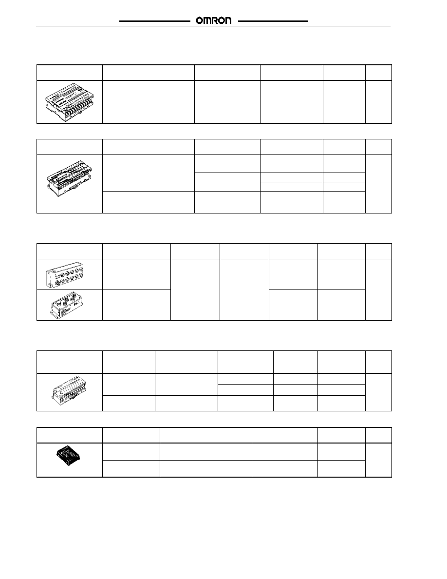
MIXED I/O LINK MODULES
Screw Terminal Model (with 16 Input and 16 Output Points)
Appearance
I/O configuration
I/O delay (typical)
Error processing
(See Note 1)
Part number
Stan-
dards
NPN compatible/
NPN open collector 100 mA/point
16 input/16 output points
Normal speed 19.2 ms
High speed 3 ms
(switch selectable)
HOLD/
LOAD OFF (switch
setting)
B7AM-6BS
------
Screw Terminal Models (with 8 Input and 8 Output Points)
Appearance
I/O configuration
I/O delay (typical)
Error processing
(See Note 1)
Part number
Stan-
dards
NPN compatible/
NPN
ll
t
100
A/
i t
Normal speed 19.2 ms
HOLD
B7AM-8B11
------
NPN open collector 100 mA/point
8 input/8 output points
LOAD OFF
B7AM-8B31
8 input/8 output points
High speed 3 ms
HOLD
B7AM-8B16
LOAD OFF
B7AM-8B36
PNP compatible/
PNP open collector 100 mA/point
8 input/8 output points
Normal speed 19.2 ms
LOAD OFF
B7AM-8F31
3
INPUT LINK CONNECTOR MODULE (M12 CONNECTORS)
10-point Terminal Models
Appearance
Description
I/O
configuration
I/O delay
(typical)
Enclosure
rating
Part number
Stan-
dards
B7A 10-point sealed
input module
NPN compatible
19.2 ms
IP67
B7AC-T10A1
UL
CSA
CE
(See
Note 3)
DeviceNet interface
module connects up to
3 B7AC modules
IP66
DRT1-B7AC
Note 3)
3
10-POINT TERMINALS
Transistor I/O Link Modules
Appearance
I/O classification
I/O configuration
Internal I/O
common
Error
processing
(See Note 1)
Part number
Stan-
dards
Input,
10 points
NPN compatible (No
two-wire sensor can
-- common
------
B7A-T10S1
UL
CSA
10 points
(See Note 2)
two-wire sensor can
be connected.)
+/-- common
------
B7A-T10S3
CSA
CE
(S
Output,
10 points
NPN open collector
100 mA/point
+ common
HOLD
B7A-R10SC01
(See
Note 3)
Printed Circuit Board Models
Appearance
I/O classification
I/O configuration
Error processing
(See Note 1)
Part number
Stan-
dards
Input, 10 points
TTL input
------
B7A-T10M2
UL
CSA
CE
Output, 10 points
NPN open collector 50 mA/point
HOLD
B7A-R10MC
CE
(See
Note 3)
Note: 1. HOLD:
The previous output condition will be on hold when an error results.
LOAD OFF: All outputs will be OFF when an error results.
2. The 10-point B7A-T10S1 and 10-point B7A-T10S3 are different from each other in terminal configuration.
3. Information on EC Directives
Individual OMRON products that comply with EC Directives conform to the common emission standards of EMC Directives.
However, the emission characteristics of these products installed on customers’ equipment may vary depending on the configu-
ration, wiring, layout, and other conditions of the control panel used. For this reason, customers are requested to check whether
the emission characteristics of the entire machine or equipment comply with the EMC Directives.
B7A Link Overview
B7A Link Overview
5
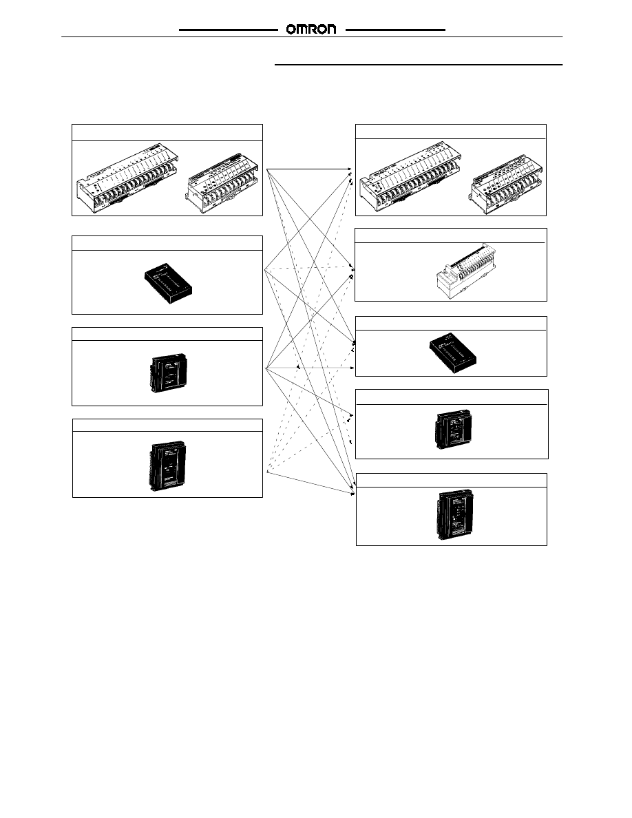
Configuration Guidelines
3
16-POINT TRANSISTOR I/O LINK MODULES
Note: The I/O delay time values of 16-point Link Terminals with Adapters are either 3 ms (typical, for high-speed models) or 19.2 ms
(typical, for normal-speed models). Use a combination of an Input and an Output Link Terminal with the same I/O delay time.
Connect two 32-point Link Terminals with Adapters together or a 32-point Link Terminal with an Adapter to two 16-point Link
Terminals.
B7A
B7A
B7A
B7A
B7A
B7A
B7A
B7A
Screw terminal model
PCB model
PCB model
Link master adapter (16 points)
Screw terminal model
Input (Transmission)
Output (Reception)
B7AS
B7AS
Link master adapter (32 points)
Link master adapter (16 points)
Link master adapter (32 points)
G70D-R6-B7A
Relay output screw terminal model
B7A Link Overview
B7A Link Overview
6
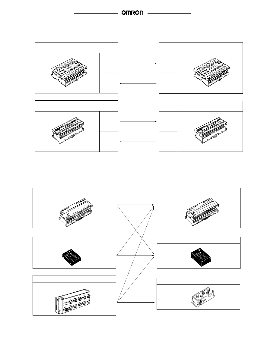
3
MIXED I/O LINK MODULES
Note: The Mixed I/O Link Terminals are either 3 ms (typical, for high--speed models) or 19.2 ms (typical, for normal--speed models).
Use a combination of an Input and an Output Link Terminal with the same transmission speed (I/O delay time).
Screw terminal model
(16 input and 16 output points)
Screw terminal model
(16 input and 16 output points)
B7AM
B7AM
Screw terminal model
(8 input and 8 output points)
Screw terminal model
(8 input and 8 output points)
Input
Output
Input
Output
Input
Output
Input
Output
B7AM
B7AM
16 Inputs/16 Output or 8 Inputs/8 Outputs
3
10-POINT TRANSISTOR I/O LINK MODULES
Note: The 10-point model has a normal I/O delay of 19.2 ms (typical); 10-point models with short I/O delay are not available.
The transmission signals of the 16-point Link Master Adapters are not compatible with those of the 10-point model. The
16-point Link Master Adapter models and 10-point models cannot be used in combination.
B7A
B7A
B7AC
B7A
B7A
M12 connector model
PCB model
PCB model
Screw terminal model
Screw terminal model
Input (Transmission)
Output (Reception)
DRT1-B7AC
connects up
to 3 B7AC
modules
DeviceNet Interface Module

B7A Link Overview
B7A Link Overview
Cat. No. GC RIO-1
04/00
Specifications subject to change without notice.
Printed in U.S.A.
OMRON ELECTRONICS, INC.
One East Commerce Drive
Schaumburg, IL 60173
NOTE: DIMENSIONS SHOWN ARE IN MILLIMETERS. To convert millimeters to inches divide by 25.4.
1-800-55-OMRON
OMRON CANADA, INC.
885 Milner Avenue
Scarborough, Ontario M1B 5V8
416-286-6465
9
Document Outline
Wyszukiwarka
Podobne podstrony:
Abolicja podatkowa id 50334 Nieznany (2)
4 LIDER MENEDZER id 37733 Nieznany (2)
katechezy MB id 233498 Nieznany
metro sciaga id 296943 Nieznany
perf id 354744 Nieznany
interbase id 92028 Nieznany
Mbaku id 289860 Nieznany
Probiotyki antybiotyki id 66316 Nieznany
miedziowanie cz 2 id 113259 Nieznany
LTC1729 id 273494 Nieznany
analiza ryzyka bio id 61320 Nieznany
pedagogika ogolna id 353595 Nieznany
Misc3 id 302777 Nieznany
cw med 5 id 122239 Nieznany
D20031152Lj id 130579 Nieznany
mechanika 3 id 290735 Nieznany
więcej podobnych podstron