The VGA standard (video graphics
array) is widely accepted as the current
industry standard. Modern VGA-com-
pliant computer monitors are capable
of handling line frequencies from
30 kHz up to 100 kHz and more. Con-
sequently, these monitors can only be
used in combination with a computer,
because the highest line frequency
supplied by most TV test pattern gener-
ators is about 16 kHz.
One serious risk of connecting a faulty
VGA display to a PC is that the fault can
also cause damage the PC, and, in
particular, the expensive video card.
A small, simple to operate display tester
like the one described here may well fill
a ‘niche’ in the market for PC acces-
sories. The fact that the tester is battery-
powered makes it ideal for quick and
efficient faultfinding and on-site testing.
Before we continue with the description
of the circuit, here are the relevant
design targets we set out to achieve:
- battery powered;
- simple and reliable
- simple to use
- adjustable frequency
- adjustable line-sync levels;
- recognisable picture on display.
In practice
Although the above list of requirements
may cause different assumptions, the
present project is simple and easy to
reproduce, even without blocking the
way to a fairly universal design. The cir-
cuit diagram of the tester is shown Fig-
ure 1. As you can see, the design is
based on common-or-garden CMOS
logic and a handful of discrete com-
ponents. Because VGA displays can
handle many different line frequencies
between (roughly) 30 kHz and 100 kHz,
there is a point in making the line fre-
quency adjustable. In this circuit, that
has been achieved by means of a sim-
14 - 9/98 Elektor Electronics
EXTRA
——————————————— PC T
OPICS
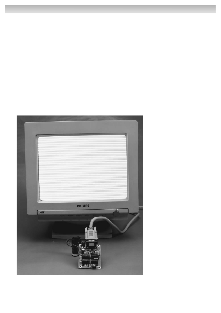
The vast majority of today’s computer displays are
VGA compatible. To be able to subject such displays
to a quick test, a signal source has to be available
that supports the rather high frequencies normally
associated with the various VGA display modes. The
VGA tester described in this article is a compact bat-
tery-powered unit that enables you to tell, at a glance,
if a computer monitor is working properly or not.
Design by B. de Graaff
small VGA-tester
check computer displays within seconds
ple R-C oscillator consisting of compo-
nents IC1d, C1, R1 and P1. In the pro-
totype, the values of the passive part s
were found to guarantee a raster fre-
quency range from 47 Hz up to 115 H z ,
which should be ample for all applica-
tions.
The clock signal is processed by four
dividers whose scaling factor is preset
by means of diodes. The divider cas-
cade IC2a-IC3b divides by 525. This
unusual divisor is achieved by making
IC2a divide by 7, IC2b and IC3a by 5,
and IC3b by 3. The pulse train supplied
by the divider cascade is shown in F i g-
u r e 2. The pulse sequence is used to
generate a colour pattern as well as
the video sync signals. More about this
further on.
From pulse to picture
Any VGA display requires three essen-
tial signals: horizontal sync pulses, ver-
tical sync pulses, and video informa-
t i o n. Most VGA displays have three
analogue inputs. Unusually, the present
tester drives these inputs with digital sig-
nals, so that the screen will only show
fully saturated colours. Based on 3-bit
colour information up to eight different
colours can be displayed: red, green,
blue, magenta, cyan, yellow, white
and black.
The circuit diagram shows that each of
the three video inputs on the monitor is
driven by a separate buffer transistor.
Each of these output drivers is pro-
tected by a 68-
series resistor to make
it short-circuit resistant and at the same
time define the desired output source
impedance.
That leaves us with the sync pulses to
K1
10
11
12
13
14
15
1
2
3
4
5
6
7
8
9
JP1
JP2
IC4b
RCX
CX
≥
1
14
15
12
13
R
10
9
11
IC4a
RCX
CX
≥
1
2
1
4
3
R
6
7
5
C2
10n
C3
120p
R6
R5
R4
R3
R2
R7
D1
D2
D3
D4
D5
D6
D7
D8
D9
13
12
11
IC1d
&
R1
P1
50k
C1
1n5
R14
1k5
R16
68
Ω
R15
T1
BC547B
R11
1k5
R13
68
Ω
R12
T2
BC547B
R8
1k5
R10
68
Ω
R9
T3
BC547B
C10
10µ
63V
C8
220µ
25V
C9
100n
C4
100n
L4805
IC5
BT1
9V
IC1
14
7
IC2
16
8
C5
100n
IC3
16
8
C6
100n
IC4
16
8
C7
100n
1
2
3
IC1a
&
5
6
4
IC1b
&
8
9
10
IC1c
&
5V
5V
5V
5V
5V
5V
5V
VGA
IC1 = 4093
IC4 = 4528
980054 - 11
D1 ... D9 = 1N4148
IC2, IC3 = 4518
CTRDIV10
IC3a
CT=0
≥
1
1
2
7
3
5
6
4
+
0
1
2
3
C
E
CTRDIV10
IC2a
CT=0
≥
1
1
2
7
3
5
6
4
+
0
1
2
3
C
E
CTRDIV10
IC3b
CT=0
≥
1
10
15
11
13
14
12
9
+
0
1
2
3
C
E
CTRDIV10
IC2b
CT=0
≥
1
10
15
11
13
14
12
9
+
0
1
2
3
C
E
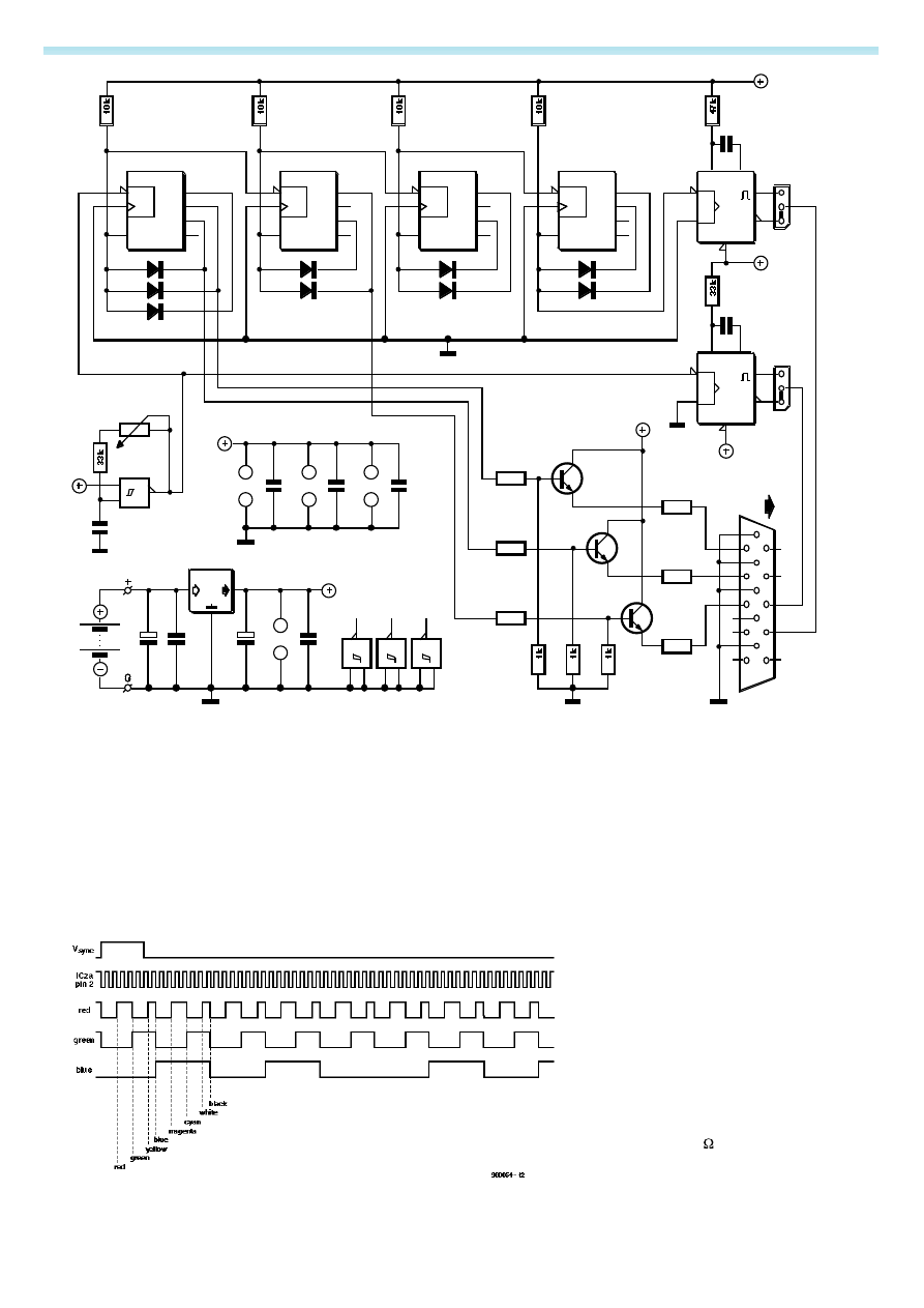
Figure 1. Circuit diagram of the VGA display tester. The circuit is simple and cheap thanks to the use of commonly available parts.
Figure 2. All the necessary signals are derived from central clock signal by means of a
divider cascade.
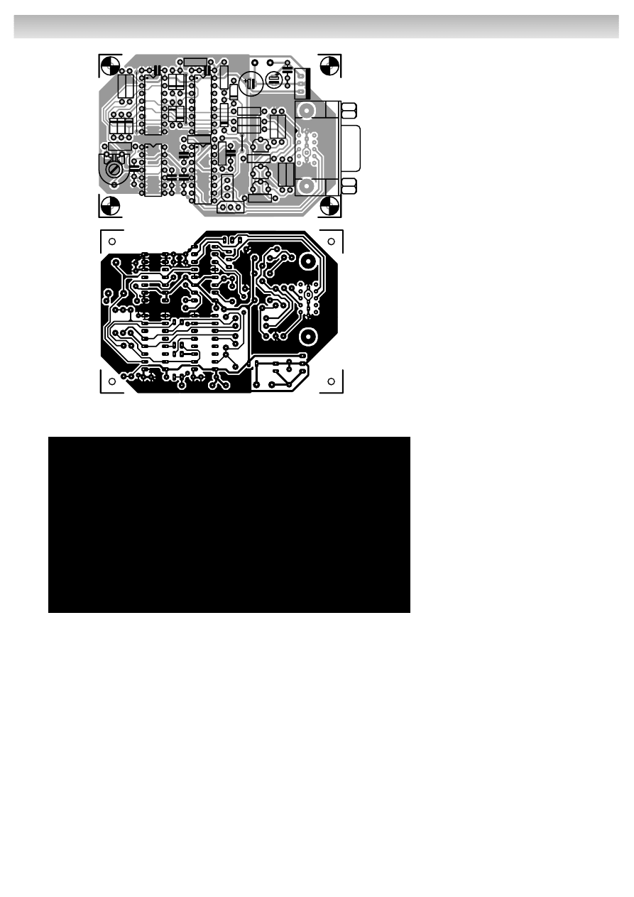
of the circuit board designed for the
VGA display tester may be found in Fig-
ure 3. The single-sided board is com-
pact, contains all parts and is simple to
fit in a small plastic case.
Connector K1 is a PCB-style 15-pin
‘high-density’ VGA socket. If so desired,
the two jumpers for the sync polarity
selection may be replaced by toggle
switches. This is, in fact, recommended
whenever the circuit is to be used ‘on
the road’.
Practical use
and adjustment
There is not much to be said about
these matters. The line frequency is
adjusted with the aid of preset P1. All
displays should be able to trigger on
the signal from about 30 kHz onwards.
The display will show a pattern consist-
ing of coloured lines. In case it is essen-
tial to test for the reproduction of indi-
vidual colours, the preset may be
replaced by a potentiometer or a
rotary switch with a number of fixed
resistors at its contacts. In this way it
becomes possible to select specific line
frequencies like 30 kHz, 50 kHz, 80 kHz
or 100 kHz. If you find it easier to work
with raster frequencies (sometimes
referred to as ‘display refresh rates’),
then the switch may be calibrated so
that you can select between, say,
50 Hz, 60 Hz, 70 Hz, 72 Hz and 75 Hz. Of
course, this requires determining the
requisite resistor values. Using a fre-
quency meter, a potentiometer and a
multimeter, these values should not be
too difficult to establish. Alternatively,
you may use a couple of fixed 10-k
Ω
resistors. The frequencies will then be
reasonably close to the target values.
Testing is very simple: use a display
cable to connect up the VGA display
to the tester. If necessary invert the
sync signals and see if a horizontal line
pattern appears on the screen. As
soon as the picture is synchronized,
you know for sure that the timing of the
display works at the frequency set on
the tester. When the bars appear in all
eight different colours, the video (RGB)
amplifiers may safely be assumed to
work all right. If colours are missing, it is
easy to determine which of the basic
colour circuits (R, G or B) is defective. If
a defect is discovered in this way, the
best thing to do is take the display to
an authorized repair shop. Attempts at
home repair are not recommended
because of the high voltages that exist
inside the display, and the fact that the
necessary circuit diagrams will rarely
be available!
(980054-1)
16 - 9/98 Elektor Electronics
EXTRA
——————————————— PC T
OPICS
Figure 3. Copper track layout and component mounting plan of the PCB designed for
the tester (board not available ready-made).
(C) ELEKTOR
980054-1
C1
C2
C3
C4
C5
C6
C7
C8
C9
C10
D1
D2
D3
D4
D5
D6
D7
D8
D9
H1
H2
H3
H4
IC1
IC2
IC3
IC4
IC5
JP1
JP2
K1
P1
R1
R2
R3
R4
R5
R6
R7
R8
R9
R10
R11
R12
R13
R14
R15
R16
T1
T2
T3
980054-1
+
0
(C) ELEKTOR
980054-1
COMPONENTS LIST
Resistors:
R1,R7 = 33k
Ω
R2-R5 = 10k
Ω
R6 = 47k
Ω
R8,R11,R14, = 1k
Ω5
R9,R12,R15 = 1k
Ω
R10,R13,R16 = 68
Ω
P1 = 50k
Ω preset H
Capacitors:
C1 = 1nF5
C2 = 10nF
C3 = 120pF
C4-C7,C9 = 100nF
C8 = 220
µF 25V radial
C10 = 10
µF 63V radial
Semiconductors:
D1-D9 = 1N4148
T1-T3 = BC547B
IC1 = 4093
IC2,IC3 = 4518
IC4 = 4528
IC5 = L4805
Miscellaneous:
JP1,JP2 = 3-way pinheader with jumper
K1 = 15-way high-density VGA socket,
PCB mount, angled pins
Bt1 = 9V PP3 battery with clip and leads.
be generated by the circuit. These
pulses are generated using two mono-
stable multivibrators (MMVs). The clock
signal of IC1d duplicates as the hori-
zontal sync pulse, triggering mono-
stable IC4a. The output of this IC sup-
plies a pulse with a length of 2.8
µs.
Since either the Q and the
Q
output
may be taken to the output by way of
a jumper, the output signal is available
in ‘true’ or ‘inverted’ form. A similar
approach has been adopted for the
vertical sync, although in that case the
clock frequency divided by 525 is used
as supplied by the divider cascade.
The vertical sync pulse is generated by
IC4b, and has a length of 175
µs. The
other three pulse signals are combined
in the video buffers (Tt-T2-T3) to provide
a line pattern with random colours.
Although the sync and video signals
are generated in a very simple man-
ner, the result is perfectly suitable for a
vast number of VGA displays.
The rest of the circuit remains limited to
a compact power supply. To ensure the
circuit works reliably on a 9-volt battery,
a low-drop 5-V regulator (IC5) has been
added. The upshot is that the tester
continues to work reliably even if the
battery is almost ‘flat’.
Construction
The component mounting plan, a.k.a.
‘overlay’ and the copper track layout
Wyszukiwarka
Podobne podstrony:
e989X12
więcej podobnych podstron