
Zbigniew Wasiak, Tadeusz Wojciechowski
Ć
w i c z e n i e nr 1
CHECKING MACHINE TOOL GEOMETRIC ACCURACY BASED ON LATHES
One of the conditions to obtain high accuracy and dimensions-shape repeatability of items made by ma-
chining is to preserve relevant geometric accuracy of machine tool. The purpose of this exercise is to learn
the methods and ways of checking geometric accuracy of machine tool, in practical part selected meas-
urements will be carried out for universal central lathe.
1. Introduction
The accuracy of each machine, and hence the machine tools for metals, is determined by:
- Geometric accuracy which is meant a dimension-shape mistakes and mistakes of relative positions of
components and machine assemblies.
- Kinematic accuracy, determined by the accuracy of kinematic couplings (joints),
- Accuracy of the adjustment, the specified precision mechanisms for traversing the dimensional setting
machine
- Precision machining.
This manual is devoted to only check the geometric accuracy of technological machine from a group of
machine tools. This check is covered by the Polish Standard PN-93/M-55580/01 title: " Dokładność geo-
metryczna obrabiarek pracujących bez obciążenia lub w warunkach obróbki wykańczającej " based on
ISO/DIS-230-1.
Checking geometric concerns the size, shape and position of the components of the machine and their
mutual displacement (surface flatness, compliance and intersecting axes, parallel and perpendicular of
straight lines, flat surfaces with respect to the surface plane or any other). It relates only to the dimensions,
shapes and relative movements which can affect the accuracy of the machine and machining. Values of
checked points must be between fix bounds, depending on the class of machine accuracy, as the elements
included in the machine tool components and assemblies are made of dimensionally-shaping tolerance
specified by the constructor. It requires that used gauges were at least a class more accurate than the
measured values.
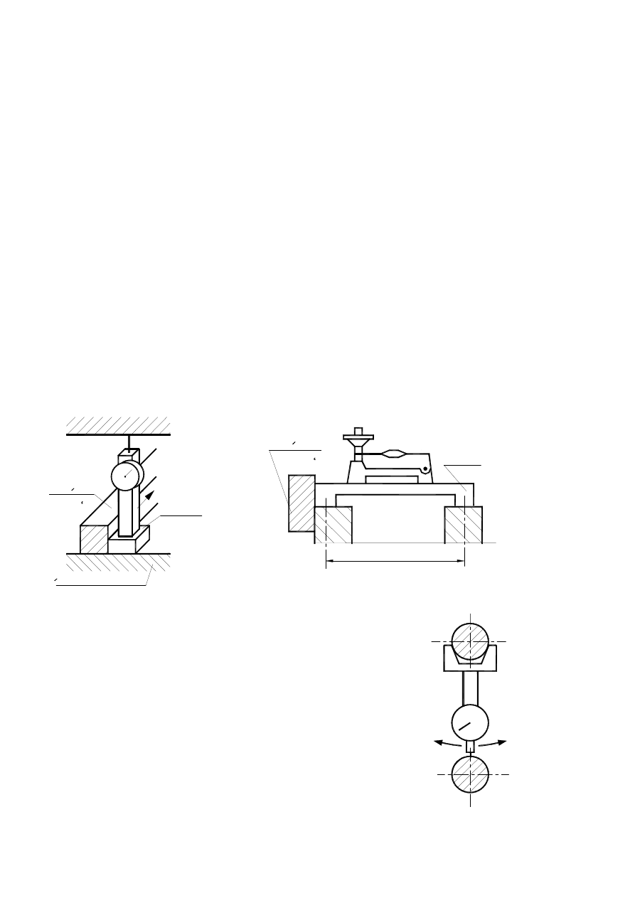
Sketch nr. 1 shows basic quantities referring to measurements during geometrical precision validation pro-
cess of shaping machine.

On vertical plane
perpendicularism
Shape deviation
On horizontal plane
surface flatness
Between two planes
parallelism
two axes or concentrici-
ty of two axes
Validation
of
Plane and axis
Coordinative
deviation
Two planes
perpendicularism
Two axes
Axis and plane
Radial
Spin imbalance
axial
Frontal plane
Distance to plane
displacement
perpendicular
Distance to axis
Distance Between
curves
Rys.1. Basic quantities concern-
ing measurements during the
process of geometrical preci-
sion validation of shaping ma-
chine.
Plane and curve
parallel
Axis and curve
Distance between
curves
2. Preliminary checking operations
- Before executing shaping machine examination, it is necesarry to place it on proper foundation and lev-
el it. By doing that machine gets its stability, which is helpful during examination,
- examination should be executed on machine Fuldy prepared to work. Disassembly of particular parts is
allowed Only special circumstances and With thorough respekt to producer instructions.,
- during geometrical examination each part (eg. Spindles) should be in the state of regular work parame-
ters (temperature should be as referred by producer instruction) ,

- geometrical examination should be exercised on idle run Or clogged machine.
3. Methods of examination
During geometrical precision examination several metods are allowed. A few of them are described be-
low on sketch nr. 1.
3.1. Line measurement process.
It refers to shaping tool's devetal ways, on which tables, sleighes or supports are being moved while
work is on. Work piece or tool are stiffly constrained with these supports, so line measurement deviations
of devetal ways are strictly related to dimensions-shape repeatability of work pieces.
Sprawdzanie to jest tematem odrębnego ćwiczenia i nie będzie tu bliżej omawiane.
3.2. Surface flatness validation.
Surface is considered as flat, when each point resides between two planes parallel to the surface and dis-
tance between planes is within flatness tolerance.
Flatness validation may be done by: estimation plate, estimation plate and indicator, ruler and size
block, ruler and strict level and indicator, strict level and also optical methodes (with autocollimator, opti-
cal angle bar and laser). Such validation is not a part of today's exercise.
3.3. Validation of planes' and lines' parallelism deviations.
Two lines are parallel to each other, when the distance between them is within parallelism tolerance on
any given normal plane.
Two planes are considered paralell, when distances betw themeen measured in at least two planes per-
pendicular to each other and to planes are equal (within parallelism tolerance).
Max. parallelism deviation is different between maximal and minimal taken result during the examina-
tion.
Differences are measured on given planes' (vertical, horizontal, perpendicular to examined plane, cut-
ting examined axis etc.) distance (e.g. on the sector of 300mm or whole plane).
During axes paralellism validation, these axes should be represented by oval planes with high accuratici-
ty of shape, relevant smoothness and sufficient lenght. If it is an interior plane, on which sensor can't be
placed, it should be taken from extra cyrindrical surface as a test tongue.
Mount and centering of test tongue is being done on its tapered end, in cylindrical or tapered hole sub-
jected to setting tool and other tools. Usually it is not possible to set-back of tongue in machining spindle
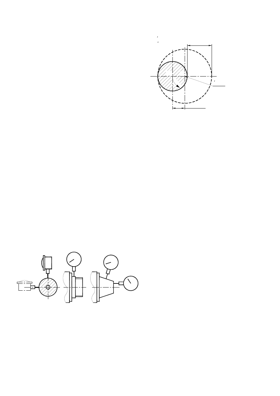
axis in a way, so it represents pivotal axis. While machining spindle rotates tongue axis describe hyperbo-
loid or tapered surface. On measured plane we can observe two extreme tongue positions B-B’ (sketch nr.
2).
Parallelism validation (when using tongue) may be done in
any given
position of machining spindle, but measure has to be repeated
after
ro-
tating machining spindle by 180
o
. Parallelism inaccuracy on
given
B'
B
A
Rys.2. Setting a tongue in an
average A position
sketch.
Wspornik
Plaszczyzna odniesienia
prowadzacy
Linial
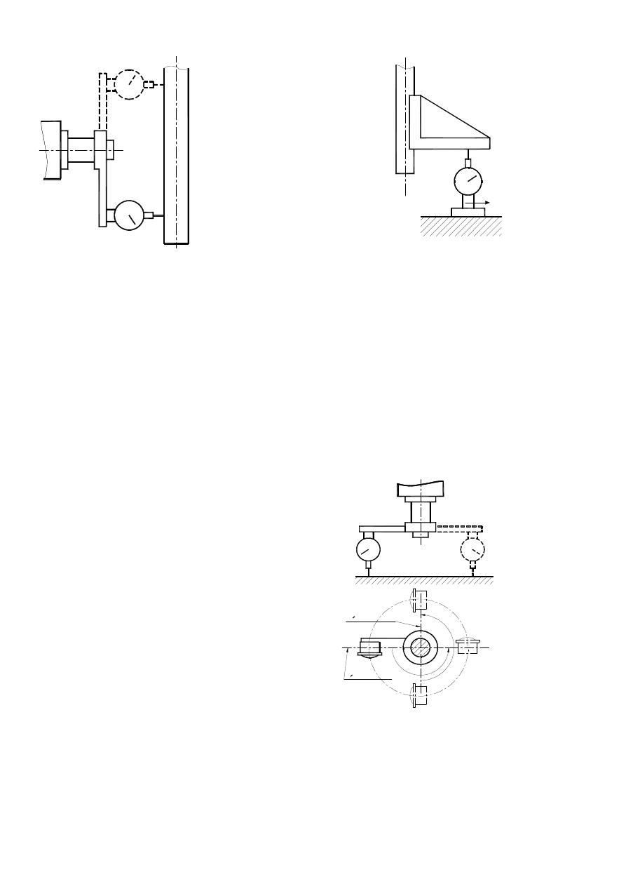
Rys.3. Test of parallelism between
two axes using ruler and indica-
tor.
plane is being set as artmetic average of both results.
Tongue may be set to middle position A. In this case, validation should be exercised only in given posi-
tion. „average whipping position” of tongue is being set by observing gauge of mesurement device, while
machining spindle is rotating slowly and there is contact between contact of indicator end with oval plane
referring to pivot axis on measured plane. Machining spindle is in middle position, if indicator’s pointer is
in middle position between its two extreme positions.
3.3.1. Validation of two planes' parallelism.
It should be performed on two planes perpendicular to each other and to given planes. There are two
methods of validation:
- with ruler and indicator
- with a strict level
In the first one dial indicator (sketch nr. 3) is constrained to console on a flat base. Is being moved tan-
gentially to ruler and moved along plane through given distance, while its test end is moving along the sec-
ond plane. In strict level method,a level is set on console connecting two comparable planes. Console is
to be moved along planes with level bound to it and get results from level. Maximal difference of results
(angle) determines angular parallelism deviation, reading (angle) multiplied by length "l" determines linear
parallelism
deviation
(sketch nr.
4).
3.3.2. Vali-
dation
of
two
axes
parallelism.
It is
done by
three methods:
- on plane by both axes
- on relative plane parallel to plane by both axes
- with a level set on horizontal plane and extra tools
3.3.2.1. In parallelism examination on plane by both axes measurement
tool
is
constrained to console allowing to move along oval shape representing
one
of
the axes test end is moving along oval shape representing the other axis.
Plytka
prowadzaca
Wspornik
l
Rys.4. Test of parallelism between two axes
using a strict level.
S. 5. Validation of
axis parallelism
on plane by both
axes.
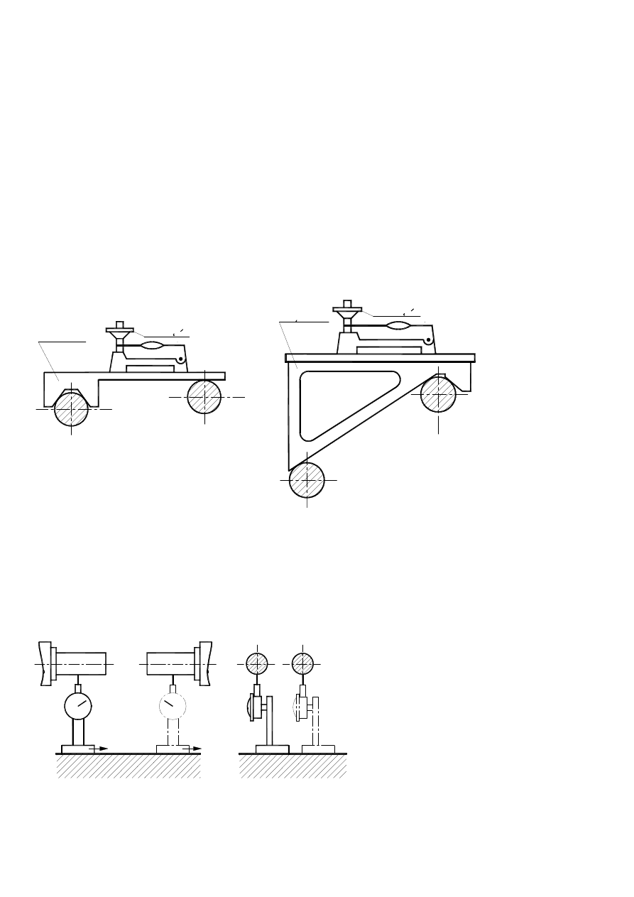
Tool has to be leaned slightly in the direction perpendicular to both axes (sketch nr. 5).
3.3.2.2. Validation may be done with extra relative plane. as much parallel to plane going through both ax-
es as possible. Each surface parallelism has to be taken into consideration separately and set it in rate to
this surface in a way described in 3.3.4.
3.3.2.3. Validation with a level set on horizontal plane and extra tools is being done in case given planes
are not both horizontal. When dip angles are narrow, extra block is used (sketch nr. 6), but when they are
wider constant angle bar or that one you can change is used (sketch nr. 7). Block or angle bar is set on two
ovals representing axes . Air bubble of a level has to be set on 0 by rotating correct handwheel.
A level with a block angle bar is moved along axis by given distance and reading of results are done.
przesuwa się Measure is related to distance between two axes. If, for instance, distance is 300mm, and
odczyt
poziom-
nicy
shows
0,06
mm/1000
mm, then
parallel-
ism devi-
ation
equals 0,018mm.
3.3.3. Validation of two axes parallelism to relative planes.
Measurements of parallelism are in fact parallelism measurements (3.3.4). parallelism referres to dis-
tance between axes and relative plane. Parallelism occurs, when plane containing axes is parallel to relative
plane. At first, measurement of both axes' parallelism to plane has to be done. Then, using the same dial
sensor
as
during
measure-
ments
of
ovals rep-
resenting
both axes,
the
dis-
tance between these axes and plane is measured. (Sketch nr. 8).
Pokretlo
Klocek
Sketch nr. 6.
Katownik
Pokretlo
Sketch nr. 7. Validation of two
axes parallelism with con-
stant angle bar.
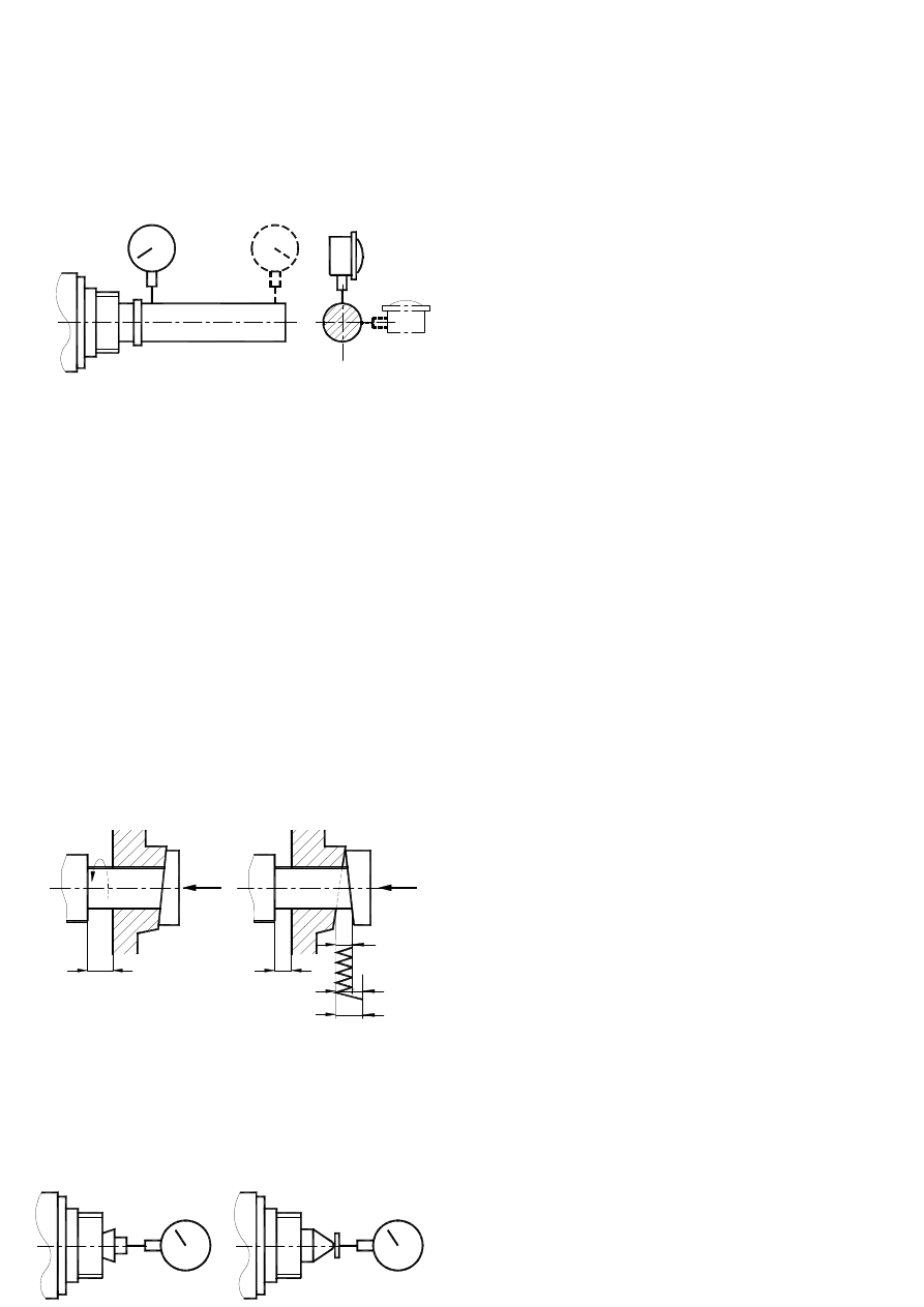
Rys.8. Test of parallelism of
A and B axis with
reference surface
sketch.
A
B
A
B
In case ovals are not identical, radial variation has to be considered.
3.3.3. Validation two axes' concentricity
3.3.3.1. Definition.
Two lines or axes are considered concentricity (which are covered by each other), when distance be-
tween them measured in several spots on given test part does not exceed particular value, referring to con-
centricity tolerance. Distance may be measured between lines themselves or between their prolongation.
Centricity inaccuracy of one axis in relation to the other is to be subjected to length of measured part. Un-
der special circumstances, extra information has to be added.
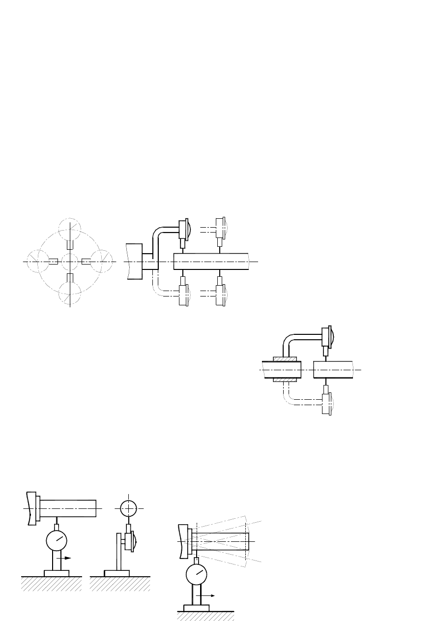
3.3.3.2. Measurement method.
Measure device is constrained to an arm and rotates full circles around axis „1”. End of indicator of
measure device moves along given A cut along oval ambit representing second axis (sketch nr. 9). Be-
cause of the
fact, that in
measured
cut,
both
axes
may
interfere
with
each
other, measurement has to be repeated in second B cut. Dis-
tance
between cuts should be as long as possible. If inaccuracy has
to
be
examined in both given planes (e.g. H and V on sketch nr. 9),
devia-
tions have to be written down separately.
In case one of the axes is pivotal axis, which handles meas-
ure de-
vice imbed on tongue reprezenting pivotal axis.
If it is necessary for measure device to rotate about fixed
oval, it
should be imbed on a ring rotating with the smallest possible
back-
lash (sketch nr. 10).
If both axes are pivotal, measured oval may be reduced to
its
whipping average position on measured plane. (3.3).
3.3.4. Validation of parallelism axis and plane.
Measure device is constrained on console with flat base and
moves
along
plane by
given vec-
Rys.9. Sprawdzanie
współosiowości
dwóch osi 1 i 2
H
V
A
B
1
2
Rys.10. Validation with device
rotating about fixed axis
Rys.11. Validation of parallelism
plane and axis.
A
B
A
B
Rys.12. Validation of
parallelism of rotat-
ing axis and plane.
tor of test end is moved along oval representing axis. (sketch nr. 11).
In each measurement spot the smallest distance is measured by moving measure device along vector
perpendicular to axis.
In case axis rotates, only setting the oval representing axis to middle position is required. Measure has to
be taken in two extreme positions. „A” and „B” (sketch nr.12).
3.4. Validation of perpendicular deviations.
Two planes, two straight lines or straight line and plane are perpendicular to each other when perpen-
dicular deviation of one in relation to the standard angle bar (representing right angle),set on the other does
not exceed maximum allowed perpendicular tolerance deviation value. Validation of perpendicular devia-
tion comes to measurement of parallelism.
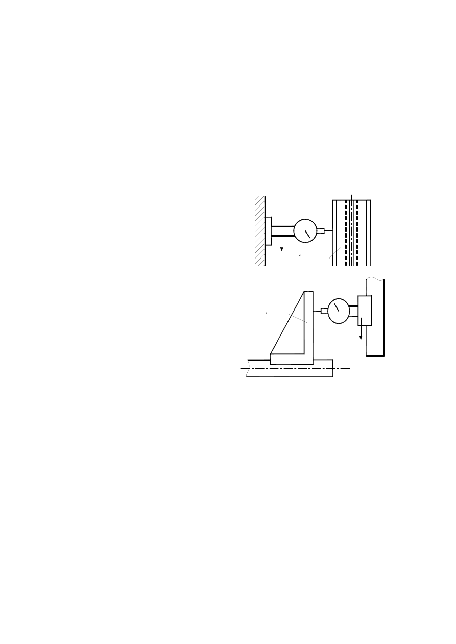
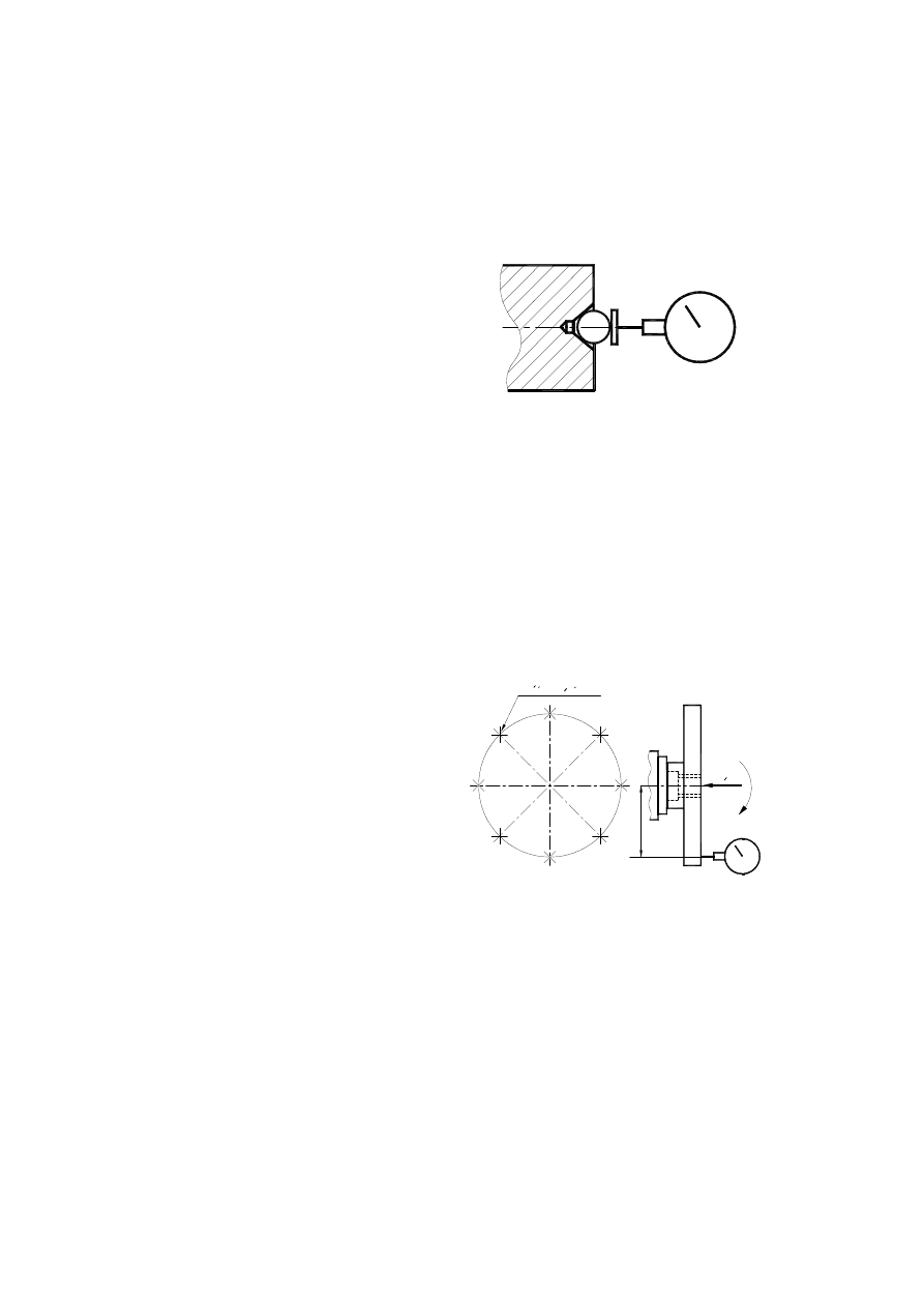
3.4.1. Validation of two planes' perpendicularism.
Cylindrical angle bar is set on one of the planes „2”
(sketch nr.13). Dial sensor is moved along the other plane,
get-
ting readings in equal parts of time. Then, cylindrical angle
bar
rotates half circle and the second set of reading is made.
From this two sets of readings are emerges average im-
age
of deviations.
3.4.2. Verification of perpendicularism of two axes.
Two cases are considered:
- both axes are fixed,
- one of the axes is pivotal.
3.4.2.1. both axes are fixed.
On oval representing one of the axes e.g. „1” an-
gle
bar with special base plate is set (sketch nr. 14). Parallel-
ism
of free arm of this angle bar and the other of the axes
„2”
is validated with methods of parallelism validation. (3.3.4).
3.4.2.2. One of the axes is pivotal.
Dial sensor is set on arm constrained to the tongue representing pivotal axis , its end touches the oval
representing the other axis on two spots A and B (sketch nr. 15). Reading differences are expressed in rela-
tion to distance AB.
1
Katownik
wzorcowy
2
sketch nr.13. Validation of planes'
perpendicularism with cylin-
drical angle bar and sensor
1
Katownik
2
Rys.14. Validation of perpendicularism
of two fixed axes „1” i „2” with
an angle bar and sensor.
If
the
other axis
is pivotal
as
well,
the
oval
represent-
ing it is
set to an
average
position of
whippng on measurement plane, using method described in parallelism validation paragraph (3.3).
3.4.3. Validation of perpendicularism of axis and plane.
Two cases are examined:
- axis is fixed,
- axis is pivotal.
3.4.3.1. Fixed axis
An angle bar with special arm of base plate is set to touch the oval representing axis. (sketch nr.16).
Parallelism of free arm of an angle bar and plane is examined in two directions perpendicular to each other
with the use of method described in paragraph 3.3.1.
3.4.3.2. Axis is pivotal.
An arm which holds a dial sensor is constrained to
machin-
ing spindle „1” (sketch nr.17) and end of indicator is set
as paral-
lel to its pivotal axis. During machining spindle rotation,
sensor
makes a circle, which plane is perpendicular to pivotal
axis.
Validation of perpendicularism of axis and plane „2”
with us-
age of end of dial sensor, comes to examining parallel
deviation
between ambit plane, which is drawn by end of indicator,
and giv-
en plane.
Such deviation is clear as a ratio to diameter of circle
drawn by
indicator during its rotation.
If measurement plane is not given, dial sensor rotates
full cir-
cle and registers the biggest variation of indicator’s read-
ing.
If measurement planes are given (e.g. planes I i II), the variation for two positions of sensor placed be-
tweeen 180 degree angle is registered for each one of the planes.
Rys.15 Validation of perpen-
dicularism of two ax-
es, when at least one
is pivotal.
←
B
A
Rys.16. Validation of perpen-
dicularism fixed axis
and plane.
→
Sketch nr.17. ScValidation perpen-
dicular deviation of pivotal
axis and plane.
Plaszczyzna I
180°
Plaszczyzna II
18
0°
1
2
This method of measurement is used for validation of perpendicularism of axis of machining spindle of
vertical mill to suraface of it’s table.
3.5. Validation of whipping
There are three types of whipping:
- radial whipping,
- axial whipping,
- front surface whipping.
3.5.1. Radial whipping
In case geometrical axis does not covered with
pivotal
axis (concentricity mistakes), (distance between axes
on plane
normal to pivotal axis on given spot is called radial
whipping
of axis (sketch nr.18).
If ovality is not considered, we get doubled value of radial whipping of axes on given sector is simply
called whipping (sketch nr. 18).
Generally measured whipping is an outcome of:
- radial whipping of axis
- ovality of diameter,
- inaccurateness of bearings.
3.5.1.1. Whipping of exterior surface
End of dial sensor is set to touch rotating plane, which is being under examination and reading of meas-
ure device during slow work of machining spindle during rotation by 360 deg. are being observed (sketch
nr. 19a). Variation of extreme positions of sensor during this process is a quantity of whipping.
On tapered surface the end of sensor is set perpendicularly to forming line. If during rotation of machin-
ing spindle
any
axial
movement
ocurrs, di-
ameter of
examined
circle will
change. Therefore, whipping on tapered surface is possible to be measured only when concurrence of cone
is not very significant. Each time before examination, axial translation of machining spindle should be
measured (sketch nr.19b), and then an influence of it on measurement should be calculated according to
concurrence angle.
3.5.1.2. Whipping of intrinsic surface
"O" - os geometryczna
O
"w" - os obrotu
w
promieniowe
Bicie
Srodek
obrotu
Bicie
sketch nr.18. Definition of „whipping”
and „radial whipping”
a
b
Rys.19. Measurement of whip-
ping of exterior surface a)
cylindrical, b) tapered
If in the cylindrical or tapered hole it is not possible to measure sensor directly, a measure tongue is
used.
If measurements are being undertaken in only one cut of a tongue, position of just one measure circle in
relation
to
axis is taken
under con-
sideration.
Because
tongue axis
may
inter-
fere with pivotal axis on measured plane, examination should be done in two separate cuts A i B along giv-
en stand-off (sketch nr. 20).
For expamle one measure should be takan near housing of a tongue (A), and the second in specyfic
lenght from (B). To eliminate mistake of set-back of a tongue in hole, particularly by tepered holes,
measures should be repeated 4 times, rotating tongue by quarter a circle each time in relation to machining
spindle. As an outcome we apply arthmetic average of these measures on both planes. Each time whippnig
should be measured vertically (position C
1
), and then horizontally (position C
2
on sketch nr. 20).
3.5.2. Axial whipping
It is a range of plane and reflexive movement along rotating full-circle axis of given part after erasing
axial backlash by adding axial force in particular direction (rys. 21). Minimal axial backlash is the smalles
value of possible translation of rotating part, measured during idle time on several spots in relation to piv-
otal axis. (rys. 21).
For purpose of eliminating the influence of resistance bearings backlash, we have to put a small value
force
to
machining
spindle
along
measure-
ment
vec-
tor. End of
dial sensor should be touching the middle of front surface and set as precise as possible along pivotal axis.
Readings are done during constant rotation of machining spindle with small speed, constantly maintaining
required clamp.
If machining spindle is cored, a short tongue should be entrench in it, with front surface normal to axis,
against
Rys.20. Validation of whipping of
intrnsic surface with a
measure tongue set in the
hole.
C1
A
C1
C1
B
C2
J
P
J
j
d
j
P
Sketch nr. 21. Description of axial
backlash by measurement of
axial whipping.
J – maximal axial backlash,
j – minimal axial backlach,
d – periodic axial movement
a
b
Rys.22. Measure of axial whipping of
cored machining spindle with: a)
short tongue and indicator, b) cir-
cle end tongue and flat indicator
which circle end of dial sensor may be based (sketch nr. 22a). A tongue with globe end may be used as
an alternative, end of dial sensor would be flat then. (sketch nr. 22b).
If machining spindle has a center hole,steel globe which has contact with flat end of dial sensor, may be
placed inside it (sketch nr. 23).
Axial whipping is determined as boundery axial translation during its full circle slow rotation with
clamp of small axial force.
3.5.3. Front surface whipping
Flat surface whipping rotating around axis is axial
whipping
of this surface. That whipping is a disadventage of flat
surface,
which does not remain normal to axis during pivot.
Whipping
is determined by distance between two planes normal to
axis,
which are set as boundaries for moving spots during its
rotation.
It is a result of several surface disadvantage and pivotal
axis:
- surface is not flat,
- surface and pivotal axis are not perpendicular,
- periodic axial movement occurs.
Because front whipping has a tendency to gain magnitude during going away from pivotal axis, meas-
urements should be exercised on ambit related to exterior spots.
During front whipping validation dial sensor
should
be set in particular distance A to center and perpen-
dicular-
ly to front surface (sketch nr. 24), then make machin-
ing
spindle rotate slowly and write down extreme indica-
tor’s
reading. Variation of these results is a quantity of
front
surface whipping. During rotation small siłę osiową
should
be put to eliminate influence of resistance bearings
back-
lash.
3.6. Validation of translation parallelism.
Translation parallelism refers to position of path of rotating machine part in relation to:
- plane (support or devetail ways),
- straight line (axis, edge of surface cross),
- trajectory of other moving machine part point.
Methods of examination are identical to these used for examination of line and plane parallelism
Measure device, if it is to be moved, should always be constrained to moving part, which should be
powered in natural way, to reveal real influence of backlash and iraccurateness of devetail ways.
Rys.23. Examination of axial
whipping using marble
placed in center hole
czujnika zegarowego
Rozne polozenia
A
1
A
osiowa
A
2
Sila
A
3
A
4
Rys.24. Validation of front whipping
of flat surface, rotating about
axis
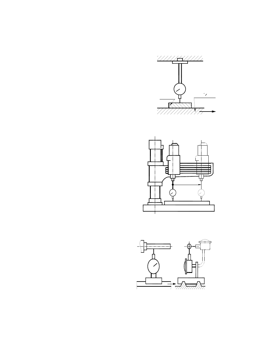
3.6.1. Validation of parallelism between trajectory and
plane.
Two cases are considered:
- plane is placed on mobile part,
- plane is placed on fixed part.
In case the first dial sensor is constrained to fixed part and its
end
lies on measured surface under right angle. Mobile part should
be
translated along given vector (sketch nr. 25), and then variation
of re-
sults indicator should be read on the lenght of this sector.
This method is used mainly for milling machine and grind-
ers,
where work piece is constrained to machining table. Dial
sensor
is set on fixed end of machining spindle as shown on
sketch
nr. 25, and table is an moving object. This is the way of
exam-
ination whether table plane is parallel to vector of its
movement.
In case the plane lies on fixed part (e.g. table of radial
drill-
ing machine) measured piece is constrained to its mobile
part
and moved with it by given vector. End of indicator
touch-
es the plane perpendicularly and moves across it. (sketch
nr.
26).
3.6.2. Validation of parallelism trajectory and axis.
Przyrząd pomiarowy is constrained to części
ruchomej and moves along given vector. End of indica-
tor
moves along a tongue representing axis (sketch nr. 27).
In
a
place where pivotal axis is, a tongue which represents it
should
be set in „place of average whipping” (3.3 - sketch nr.
2). If
each plane is the same to all other, measurement should
be
done on two planes perpendicular to each other.
3.6.3. Validation of parallelism between two trajecto-
ries.
maszyny
Stol
Listwa
Rys.25. Validation of parallel-
ism of table to trajectory
of it’s move
Rys.26. Validation of parallelism of
trajectory of movement of
radial drill spindle totable
axis.
Rys.27. Validation of parallelism tra-
jectory and axis.

Dial sensor is set on one of mobile parts,
so its end touches the second mo-
bile
part in given spot. Both parts are
being
moved together, along same vec-
tor,
reading of measure device are be-
ing
observed during process (sketch
nr.
28). In case when parallelism of
trajec-
tories on two given planes is sig-
nifi-
cant (e.g. horizontal and vertical), measures should be done on both planes.
3.7. Validation of translation perpendicularism
Translation perpendicularism for machining tools refers to subsequent positions of particular spot of
mobile part of machine in relation to:
- plane (base or devetail ways),
- straight line (axis or edge of two planes' crossing),
- path of other mobile part spot.
In this process, previously used methods subjected to translaton parallelism measurements are applied.
4. Progress of the task
Before executing this exercise student should:
- check, whether machining tool is in heat-set state,
- plug it out of electric network,
- get know with machining tool handling procedure required to execute task.
- get know with measure devices required to execute task.
- clean surface of contact between machining tool and measure device.
Execute practice part of the task, examining deviations of quantities assigned to protocol.
5. Compilation of results.
Results calculated during task should be written into protocol of geometrical acuteness. Upon calculated
results, form wrap-up, which should consist of:
- picking observed geometrical deviations exceeding admissible deviations,
- Sum up its influence on dimention-shape acuteness of made object.
Rys.28. Validation of
parallelism be-
tween two trajec-
tories.

Wroclaw University of Technology
Name, Surname:
Institute of Machine Technology and Automation Study:
Year: Group
Exercise data:
Exercise 1
CONTROL OF MACHINE TOOL GEOMETRY
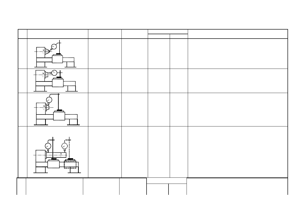
6. Measurement protokol
LATHE TYPE . . . . . . . . . . . . Span between centers (DC) . . . . . . . . . . . . . . Maximal diameter over the bed D
a
-. . . . . . . . . .Factory number . . . . . . . . . . . Production date
………………….
No
Sketch
Measured value
Measure tools
Deviations [mm]
Measurement description
max.
measured
1
Spindle
center
pulsation.
Sensor with
sensitivity
0.001 mm
0.015
Dead center mount inside the spindle. End of sensor
mount perpendicular to cone surface. Rotate spindle by
hand with little speed and read maximal and minimal
values. Measured deviation divide by cosα. α is a half
of cone center angle value.
2
Spindle face pul-
sation.
Sensor with
sensitivity
0.001 mm
0.02
Put end of sensor to spindle face in perpendicular di-
rection. Rotate spindle by hand with low speed without
stop. Read indications.
3
End of spindle
outside
center
surface
pulsa-
tion.
Sensor with
sensitivity
0.001 mm
0.01
Put end of sensor to end of spindle outside center sur-
face perpendicular. Rotate the spindle constantly with
little rotation speed. Read maximal end minimal val-
ues.
4
Spindle
inside
surface
radial
pulsation.
a) near a spindle
face
b) in a distance
D
a
/2
but
not
more
than
300mm
Measure
mandrel,
sensor with
sensitivity
0.001 mm
a) 0.01
b) 0.02
Put measure mandrel inside the spindle cone. Put end
of sensor to mandrel surface perpendicular. Rotate
spindle by 2
π
angle at least and read maximal and
minimal values. Measurement should be done in two
crosses places: a) near the spindle face and b) at the
end. Measurement replace four times with spindle po-
sition changing on
π
/2 angle. Final deviation is a mean
value of four measured deviations in two crosses.
Measurement do in two perpendicular directions (ver-
tical and horizontal).
No
Sketch
Measured value
Measure
tools
Deviations [mm]
Measurement description1
max.
measu-
red.
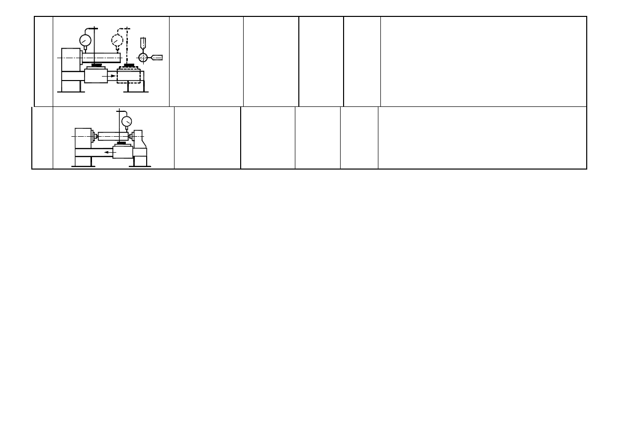
5
b)
a)
Control of parallel
spindle axe to par-
allel
cross-way
move a) vertical
and b) horizontal.
Measurement
mandrel, dial
sensor 0.001
mm sensitivi-
ty.
a)
0.015/300
in vertical
direction
b) 0.02/300
in parallel
direction
Fix the mandrel into spindle cone. Fix the dial sensor in
stand on the cross-way. Put end of sensor to mandrel
surface in vertical direction. Move cross-way parallel to
spindle axis and observe the dial sensor indications.
Rotate the spindle about
π
angle and repeat measure-
ment. Describe parallel deviation as mean value of two
measured deviations. Repeat measurement in horizontal
direction.
6
Height of axes
Difference
Sprawdzenie
różnicy wysoko-
ś
ci osi wrzecio-
na i osi konika
Measure
mandrel,
sensor with
sensitivity
0.001 mm
0.04 horse
axe higher
than spin-
dle axe
Tail stock and his bush blocked as in regular work.
Mount mandrel inside the tail stock bush. Mount sensor
to cross way. Put end of sensor to mandrel surface and
read measured values on the mandrel ends.
7. Conclusions.
Ad.4
Vertical surface
Horizontal surface
A
B
A
B
0
min
Deviations
min Deviations
min Deviations
min Deviations
max
max
max
max
2
π
min
Deviations
min Deviations
min Deviations
min Deviations
max
max
max
max
π
min
Deviations
min Deviations
min Deviations
min Deviations
max
max
max
max
π
2
3
min
Deviations
min Deviations
min deviations
min Deviations
max
max
max
max
4
Ad 5.
Vertical surface
Horizontal surface
0
A Deviations
………………….
A Deviations
……………….
B
B
π
A Deviations
……………………
A Deviations
………………….
B
B
Average deviation
…………………….
Wyszukiwarka
Podobne podstrony:
INSTR KLASYF DLUZNE
więcej podobnych podstron