
TOOL FAILURES -CAUSES AND PREVENTION
I. Jung
Düsseldorf Böhler
V. Lubich
Edelstahlwerke Buderus AG
Wetzlar
H.-J. Wieland
Verein Deutscher Eisenhüttenleute
Düsseldorf
Abstract
The aim of this project by the VDEh Subcommittee on Tool Steels is to docu-
ment the various types of tool failure occurring from the design through to the
tool application stages. Apart from systematically classifying these failures
according to type and occurrence, the project is intended to deliver practical
solutions to the problems associated with the respective failure modes.
Manufacturing defects, operating errors and unforeseen events all have
an impact on tool service life. Heat treatment naturally plays a major role
due to its significant influence on the tool properties, and indeed most defects
appear after the heat treatment stage. Especially with some more recent heat
treatment methods, remedial action is undoubtedly called for.
To optimize the service life of a given tool, failures must be minimized in
all manufacturing steps going into its production and its proper use must be
ensured. A register of tool failures covering the full range of failure sources
can therefore contribute significantly to a tool service life improvement and
hence, to more efficient manufacturing.
1343

1344
6TH INTERNATIONAL TOOLING CONFERENCE
INTRODUCTION
The present project was set up to record the numerous problems cur-
rently observed in the heat treatment and use of tool steels, and to develop
appropriate suggestions and remedial strategies.
Heat treatment problems are mostly attributable to a lack in structural
toughness resulting in premature failure in the form of tool breakage/fracturing.
This problem has several causes, one of which is the widespread conversion
of virtually all heat treatment operations to vacuum-hardening technology.
The previously common brine hardening method has become rare as a result
of environmental considerations. However, it had the advantage of per-
mitting quenching at variable rates in oil, air, or water. With the vacuum
method, the quench rate lies somewhere between air and oil quenching, i.e.,
it is slower than in the brine hardening process. In addition, quench rates
are now influenced significantly by the furnace load and hence, the degree
of furnace capacity utilization. This essential parameter, which eludes mea-
surement, defines the quench rate in today’s applications.
Several years ago, the exodus of toolmaking operations to low income
countries began as part of corporate outsourcing strategies. Today, heat
treatment operations in these countries are focused mostly on standard tools
while the production of high performance products has mostly reverted to
western Europe. But premature tool failures due to defects (including heat
treatment failures) are particularly critical in high performance tools pushing
the limits of achievable material properties. An optimized heat treatment can
help greatly in these cases to make the performance potential of such high
performance tools fully accessible.
The working group’s original subject was therefore extended to include
all tool failures currently observed, whether in toolmaking or downstream
operating contexts. The aim was to systematically record and classify all
failures according to type and occurrence while offering solutions at the same
time. A key factor here is that many failure-causing tool defects will appear
conspicuously often and over long periods after the introduction of new
manufacturing methods as the latter are becoming increasingly widespread
(as was the case with spark-erosion methods a few years ago). Here we have
the opportunity to identify such systematic failures and to suggest remedial
approaches. A comprehensive description of all tool failures observed is of
special importance inasmuch as the performance of a given tool is determined

Tool Failures -Causes and Prevention
1345
by numerous and diverse factors, from design through to the toolmaking,
finishing and heat treatment stages and, ultimately, service conditions. We
are looking at a control loop in which all subordinate steps contribute to
the tool’s behaviour. To maximize service life, it is therefore important
that each such subordinate step is performed in a virtually flawless manner.
A Tool Failure Register of the type now being compiled should contribute
effectively to an improvement in tool service life.
TOOL FAILURES AND THEIR SIGNIFICANCE
Our understanding and prevention of tool failures must be viewed from
several perspectives:
Prevention of economic loss to
Tool users
Tool manufacturers
Steelmakers
Safety issues, i.e., the need to ensure
Operating safety
Labour safety
Environmental safety
Compliance with quality assurance requirements, e.g., QS 9000
Performance and service life improvement
Increased production reliability, since tool failures usually entail pro-
duction disruptions up to the point of a production shutdown.
The overall economic loss resulting from tool failures is significant, given
any analysis of tool failures from a business management viewpoint must
today reflect the resulting processing and consequential costs, which usually
amount to many times the costs of material. The service life improvement
potential is not yet factored into this equation. As a general estimate, it
can be stated that a 20 - 25% performance increase is achievable across
all tools. In other words, the economic potential of many tools is far from

1346
6TH INTERNATIONAL TOOLING CONFERENCE
being adequately utilized. With manufacturing failures now being routinely
trackable to the source, the associated costs can be charged on all the way
to the liable party. Given the large number of different production steps
involved in toolmaking today, all companies contributing to the process
are forced to furnish evidence of zero defect manufacturing. Under this
aspect too, a detailed understanding of tool failures and their prevention is
an economic must.
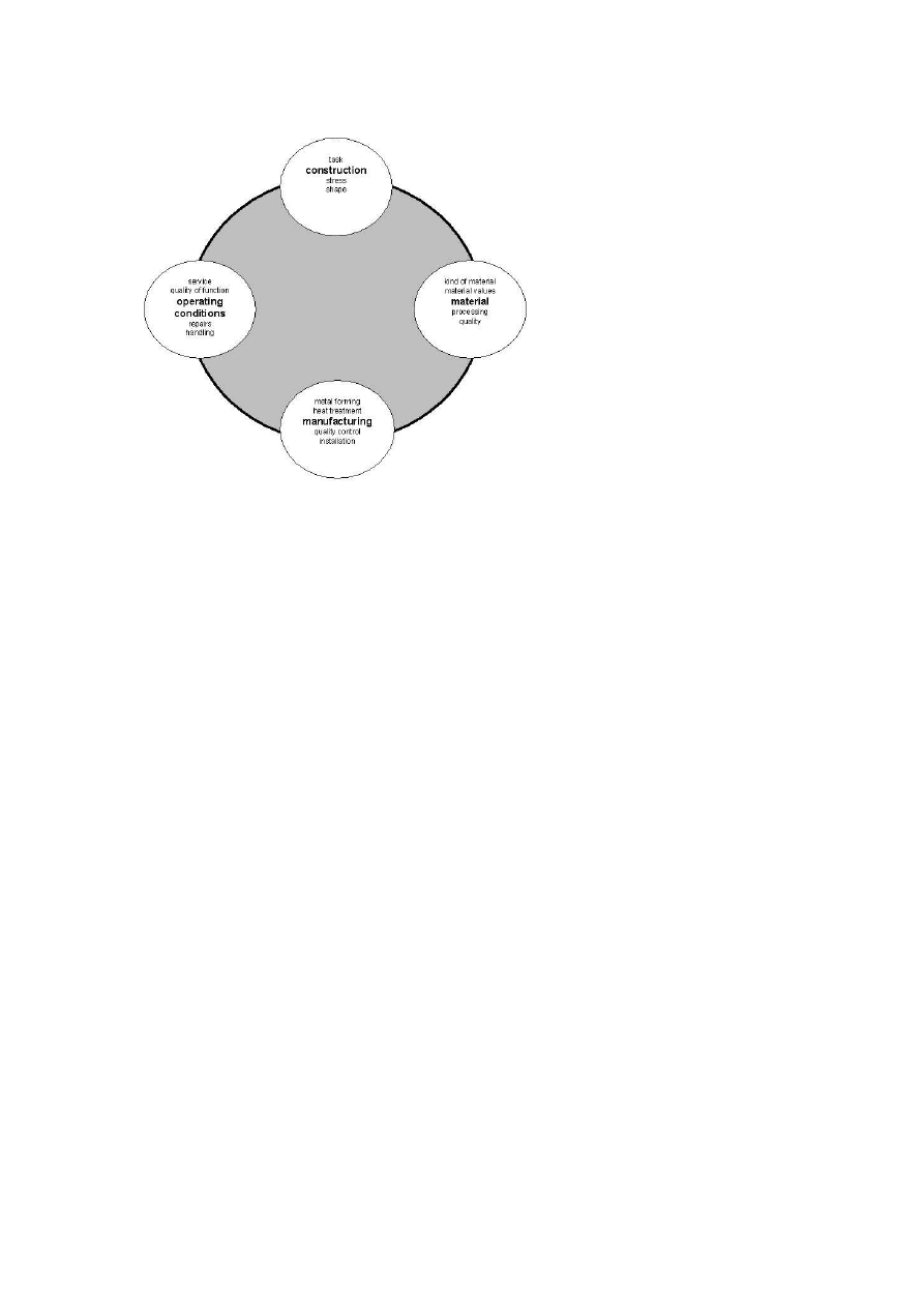
INFLUENCES ON TOOL SERVICE LIFE
The factors determining the service life of a tool may be viewed as a
control loop starting with its design and ending with its use, Fig.1. As early
as during the design stage, the tool’s essential load bearing capability is de-
termined via shape and load rating calculations. At the materials level, a
steel grade is selected and desired finish and working hardness are deter-
mined. Incorrect design specifications and an improper choice of materials
will usually result in tool breakage or deformation. At the manufacturing
stage including machining and heat treatment, the design specifications are
then put into practice. Failures in this phase (and specifically heat treatment
failures) will usually reduce the toughness of the tool, possibly resulting
in tool failures due to breakage. In use, failures may occur as a result of
improper handling, maintenance or repair practices, which likewise tend to
result in breakage.
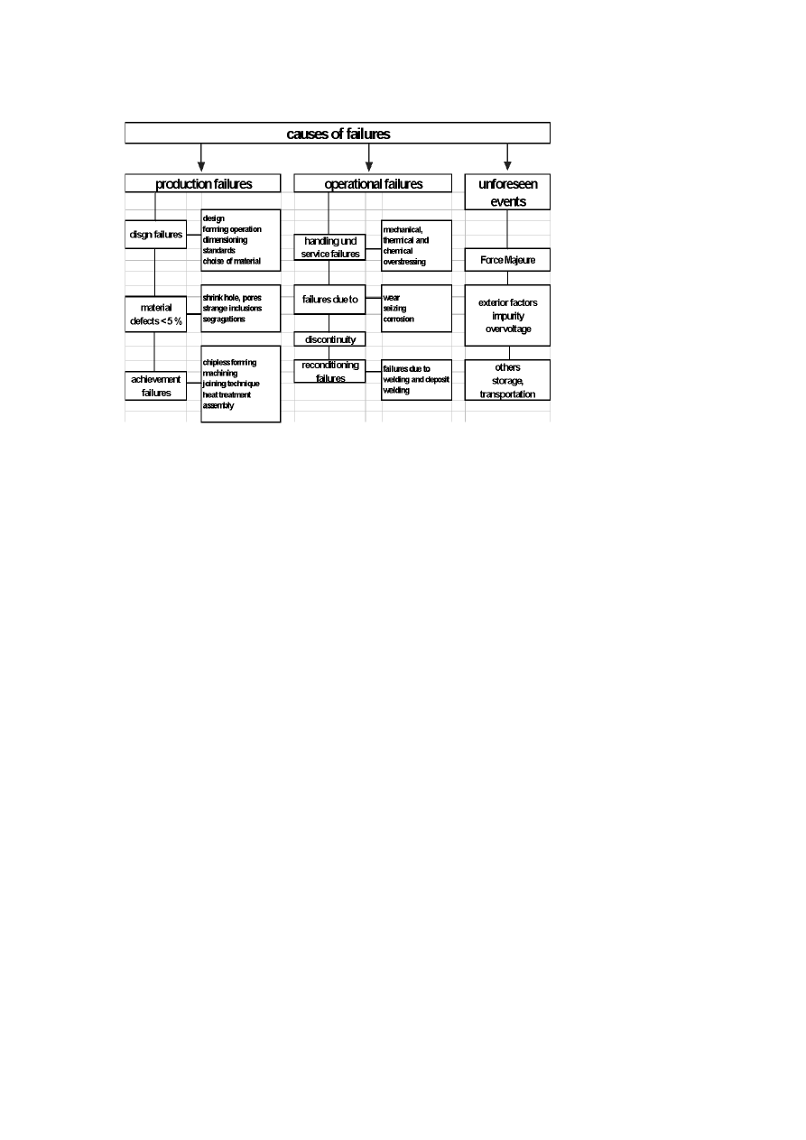
MOST FREQUENT TOOL FAILURE CAUSES
If we classify tool failures according to the various failure causes, Fig.2,
it emerges that these causes are essentially threefold. The highest frequency
can be found among manufacturing failures falling into the tool production
cycle (design, material, and execution defects), followed by operating errors
at the tool application stage (handling, maintenance and repair defects and
consequential effects). Unforeseen events (Force Majeure, exterior factors)
are much rarer. Of all failures observed, defective material accounts for no
more than 5%. Execution (finishing) and heat treatment emerge as the most
common failure sources.
Tool Failures -Causes and Prevention
1347
Figure 1.
Influence on the life-cycle of a tool.
INVESTIGATION OF TOOL FAILURES
The investigation of tool failures comprises several stages. Starting with
the macroscopic analysis, cracks and fracture paths, pores and fracture sur-
face features are evaluated. Chemical tests identify cases of incorrect mate-
rial identity. Hardness testing is conducted to check for an adequate working
hardness or, where appropriate, hardness distribution. The main instrument
in tool failure analysis is the metallographic investigation, which determines
material properties on the one hand (carbide distribution, cleanliness, grain
size) and material defects on the other (porosity, shrinkage holes, excessive
segregation, inclusions). Machining defects (grinding or erosion faults) are
likewise detected at this stage. The core element of any metallographic in-
vestigation is the inspection of the microstructure imparted by heat treatment
(tempering condition, retained austenite, banding, coarseness and decarbur-
ization).
1348
6TH INTERNATIONAL TOOLING CONFERENCE
Figure 2.
Classification of tool failures.
THE TOOL FAILURE REGISTER
CLASSIFICATION OF TOOL FAILURES BY DEFECT
TYPES
The Tool Failure Register is classified according to the most common
defect types and their causes, Table 1. Due to the large number and diversity
of failures encountered, we can merely give a selection of the currently most
common failure causes here. The results of the data collected to date shows
that fractures are by far the most dominant cause, accounting for 70% of all
tool failures. Of the remaining failures, about 10% each were due to wear,
cold weld/seizing phenomena and other causes.
Tool Failures -Causes and Prevention
1349
SELECTED EXAMPLES OF TOOL FAILURES
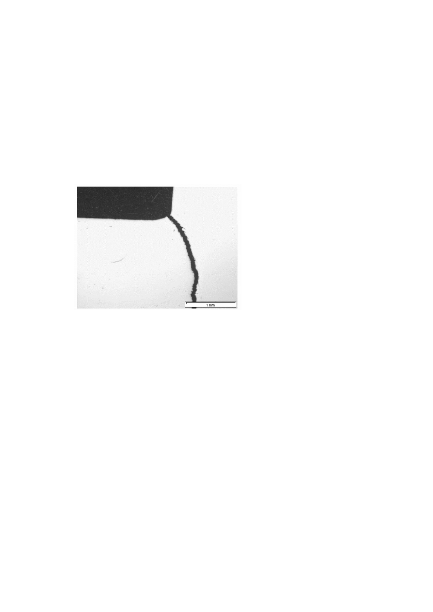
Design failures.
One common design failure are sharp edged radii which
cause a pronounced notch effect when the tool is operated under load and
may cause it to break if its tensile strength is exceeded. An example of
such flawed design is illustrated in Fig.3. The product in question is a die
insert made of a hardenable corrosion resistant high wear chromium alloy
die steel (BÖHLER M 340). Cracking has occurred due to the high notch
stress along the sharp edged radius. This might be remedied by providing
a maximum radius in all load bearing areas. Another effective reduction of
the radius notch effect can be achieved by polishing the radius surfaces. If
these measures should still not give an adequate fracture resistance, a tougher
material must be used.
Figure 3.
Crack initiation at the sharp radius of a plastic mould die of a hardenable
corrosion resistance plastic mould steel.
Material defects.
Given today’s high levels of process reliability, mate-
rial defects in steels sourced from technologically advanced countries have
become rare. On the other hand, a large number of imported tool steels reach-
ing the Western Europe market does not always meet EN ISO 4957 material
quality standards. The number of internal and surface defects observed (e.g.,
shrinkage holes, porosity, excessively decarburized surfaces, metalworking
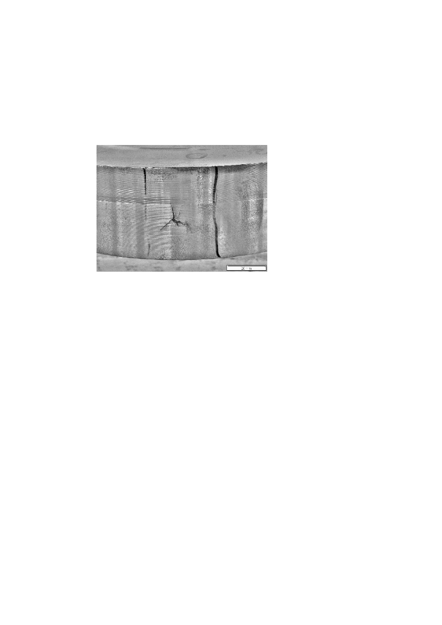
1350
6TH INTERNATIONAL TOOLING CONFERENCE
cracks) has been on the increase again in recent years, as shown here for a
HS6-5-2C (material No. 1.3343) steel bar in Fig.4. Material failures of this
type are found specifically in steels from CIS countries and emerging Asian
markets. The damage caused by such material defects is particularly high
since they will usually entail substantial consequential costs, e.g., machining
costs, production shutdowns, and the like. The loss to the overall economy is
considerable, although the material costs of a contemporary tool will usually
account for only 5% of the defect costs described.
Figure 4.
Forging failure at the outer surface of a round bar (253 mm Ø) of steel grade
HS6-5-2C (steel number 1.3343).
Machining failures.
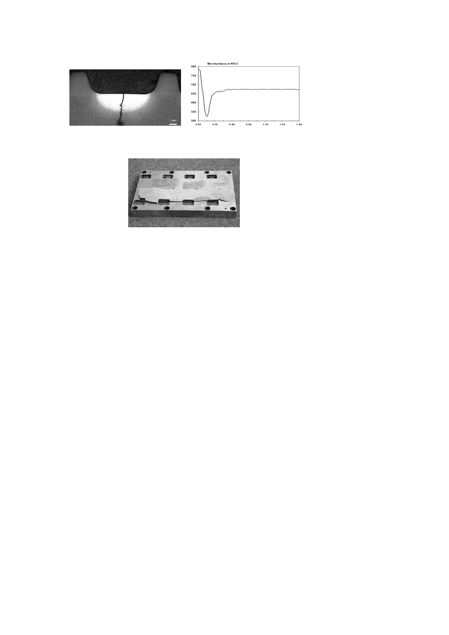
Grinding failures.
The following is an example of a grinding failure. The
tool in question is a forming roll made of BÖHLER K 340 (∼X110CrMoV8-
2) hardened to 60 HRC, which failed shortly after commissioning. A met-
allographic section through this roll shows a conspicuously bright area of
increased hardness exhibiting a penetration depth of approx. 3 mm at the bot-
tom of the profile in which a further secondary crack can be identified Fig.5a.
Such rehardened zones consist of untempered brittle tetragonal martensite
which is naturally susceptible to cracking. When the tool operates under
load, incipient cracking may easily occur in this increased hardness area

Tool Failures -Causes and Prevention
1351
and may propagate into the basic microstructure. The hardness distribution
in a surface damaged by grinding is shown in Fig.5b; the excessive hard-
ness in the rehardened zone, the hardness drop in the underlying tempered
zone and the subsequent hardness increase in the core structure are easily
identifiable. These variations in structural conditions and hardness produce
an unfavourable internal stress distribution, mostly accompanied by tensile
stress, which renders the surface sensitive to cracking. The intensity of such
stresses can be seen in Fig.5c: on this plate made of 90MnCrV8 steel (ma-
terial No. 1.2842), high tensile stresses in the surface have caused a large
area to chip off and rise up several millimetres. The only way to prevent
microstructural damage during grinding is to provide adequate cooling. It
should be noted here that in terms of cooling performance, today’s grinding
emulsions with their increasingly high water content, a concession, inter
alia, to environmental concerns appear to be more inferior to emulsions with
higher oil content than has so far been assumed. The minimal lubrication
principle widely adopted today additionally imposes higher heat loads on
the ground surface, thus increasing the risk of rehardening.
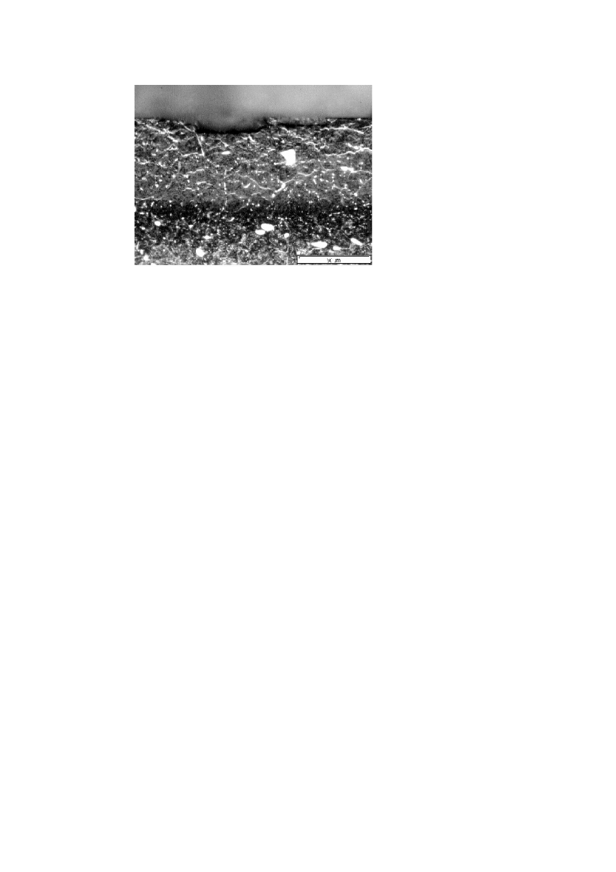
Erosion failures.
Erosion machining with excessive power inputs is an-
other widespread cause of failure. Especially with highly alloyed tool steels,
excessive power levels may give rise to significant surface damage. Fig.6
shows a metallographic specimen of the coarsely spark-eroded surface of a
high alloyed cold work steel grade. The extensive melted zone, with incipi-
ent cracks due to thermal overloading, is clearly identifiable. Underneath it
we can see a rehardened zone consisting of brittle tetragonal martensite, as
in the case of the grinding defect outlined above. The incipient cracks in the
melted zone subject to tensile stress may easily propagate under load into
the brittle rehardened zone; they frequently extend along the carbide bands,
as will be easily appreciated from Fig.6, and will ultimately cause the tool
to fail. As with grinding failures, we can observe an uneven hardness dis-
tribution along the eroded surface. Fig.6 illustrates the high hardness of the
melted zone, the even greater hardness of the underlying rehardened area,
the hardness drop in the underlying highly tempered area, and the following
gain in hardness toward the core microstructure. Here too these inhomoge-
neous structures and hardness levels create an unfavourable internal stress
situation.
1352
6TH INTERNATIONAL TOOLING CONFERENCE
(a) Grinding crack with hardening zone in a
grooved roll of high alloyed cold work tool steel
(Etchant: 3 % HNO
3
).
(b) Variation in hardness within the hardening
zone of the grooved roll in Fig.5a.
(c) Crack initiation during spark erosion due to
high internal stresses, caused by grinding with-
out sufficient cooling (hardened and tempered
plate of steel grade 90MnCrV8 (steel number
1.2842).
Figure 5.
This situation can be remedied by minimizing the power input into the tool
during spark erosion. Continuous erosion under fine machining conditions,
at low current and high frequency, is preferable. Following the erosion
process, the product should be tempered again at about 30 – 50 K below the
last tempering temperature to transform the rehardened zone into a tempered,
tougher martensite. The melted zone should be mechanically abraded by
grinding, polishing or micro peening.
The cracking phenomena frequently observed in erosion-machining of
hardened tool steels a few years ago due to internal stresses associated with
low tempering temperatures have become quite rare these days since most
tools are now subjected to secondary hardening prior to erosion and are
largely free from internal stresses due to their highly tempered state.

Tool Failures -Causes and Prevention
1353
Figure 6.
Spark eroded surface mit significant melting zone, new hardened zone and
high tempered area of a high alloyed cold work tool steel. Microstructure and variation in
hardness.
Nitriding failures.
Tool steels are nitrided to increase the wear resistance
of their surface. Another benefit of nitriding lies in the creation of subsurface
compression stresses which protect against cracking. The increase in wear
resistance is due to the penetration of nitrogen into the tool surface, although
it must be said that with high alloyed tool steels, a "pile-up" of incoming
nitrogen and the resulting formation of nitrides are a common risk. Such
nitrides will form mainly at the grain boundaries, where the nucleation energy
is minimal and more space is available due to lattice deformation. These
grain boundary nitrides actually weaken the grain boundary, often to the point
where entire grains become dislocated from the lattice, Fig.7. With higher
alloyed tool steels, care must therefore be taken to prevent excessive nitrogen
concentrations during nitriding. Optimum levels are easiest to achieve with
plasma nitriding or fast acting nitriding solutions. Thus, nitriding is a process
which yields high performance improvements when properly carried out, but
may just as easily shorten the tool life when improperly applied.
Heat treatment failures.
Quench stress cracking.
Quench stress cracking is a stress relieving
phenomenon produced by high thermal and transformation stresses, usually
1354
6TH INTERNATIONAL TOOLING CONFERENCE
Figure 7.
Metallographical section through a overnitrided surface of a drawing die of
steel grade X153CrMoV12 (steel number 1.2379) with significant nitride layers on the grain
boundaries (Etchant: 3% HNO
3
).
during quenching from the hardening temperature. It is facilitated by an
unfavourable tool geometry, such as uneven mass distributions with pro-
nounced differences in cross section, the notch effect of sharp edged radii,
etc. Fig.8 shows a die made of X38CrMoV5-1 (material No. 1.2343) which
is fairly large at 450×195×800 mm; it was quenched and tempered to a work-
ing hardness of 46 HRc, corresponding to 1500 MPa. The heat treatment
was conducted in a shielding gas atmosphere, with subsequent quenching
in oil to room temperature. The quench stress crack shown here extends
along a critical die contour with a sharp edged groove. Remedial measures
in this case would have to include an optimized design of the die contour
for the heat treatment, and a modification of the sharp edged groove. To
reduce thermal stresses between the edge and the core, a soak cycle during
the cooling phase or an "interception" at 150℃ for subsequent tempering
would be recommended.
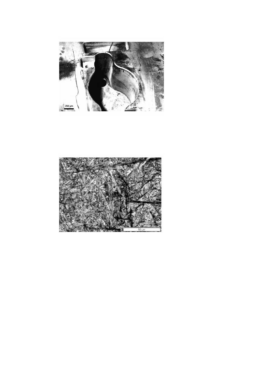
Another quench crack is illustrated in Fig.9. The tool in this case is a
forging die made of grade X38CrMoV5-1 steel (material number 1.2343)
which exhibits an unfavourable mass distribution as well as some extremely
thin walls in its contoured area. The quench crack originates in the thin wall

Tool Failures -Causes and Prevention
1355
Figure 8.
Stress relieved crack of a die casting die of steel grade X38CrMoV5-1 (steel
number 1.2343) following a sharp edged groove.
of the contour which, to make matters worse, is quite sharp edged. The re-
sulting notch effect, in conjunction with the high thermal stress encountered
in the quench, is responsible for the formation of this defect. Here, too, a
remedial strategy would have to focus on an improvement of the tool contour
that eliminates sharp edged radii and major thickness differences. Soaking
to relieve thermal stresses would be recommended.
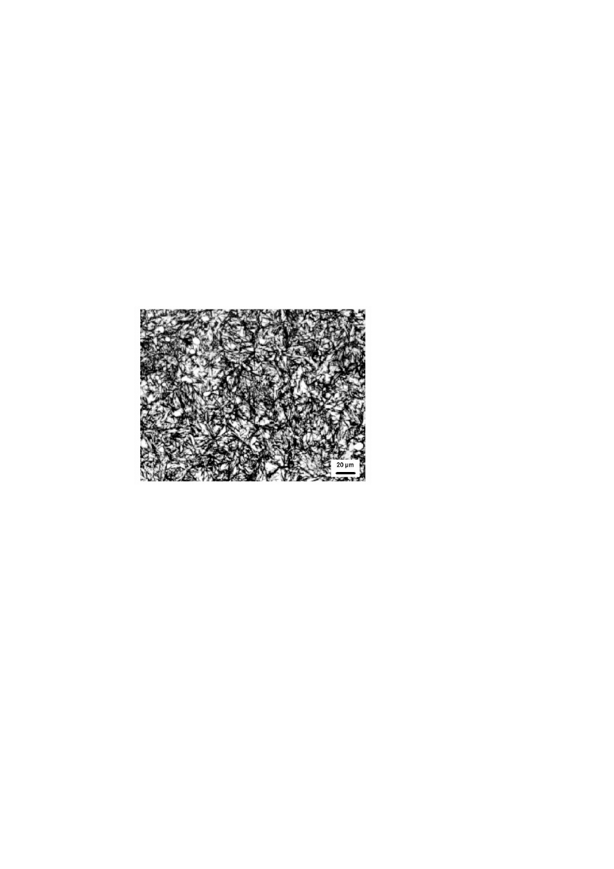
An unfavourable tempered microstructure may likewise give rise to quench
stress cracking. Fig.10 presents the coarse-grained tempered structure of an
aluminium die casting die made of 38NiCrMoV5-1 grade steel (material No.
1.2343) with a working hardness of 45 HRc. This tool exhibited a quench
crack after heat treating, indicating a low toughness of the coarse-grained
superheated structure. The die was heat treated at 1020℃ with subsequent
hot quenching at 180℃. It should be noted that in this case, no stress reliev-
ing was performed after the coarse machining step. The internal stresses
introduced by the machining cycle thus further facilitated the formation of
cracks. Remedial measures would have to include stress relieving at about
650℃ after the machining step, a reduction of the heat treatment temperature
to 1000℃, and the adoption of hot quenching at 550℃ to reduce the risk of
quench stress cracking.
Below we shall be looking at a number of typical heat treatment fail-
ures which are associated with unfavourable microstructures and reduced
1356
6TH INTERNATIONAL TOOLING CONFERENCE
Figure 9.
Stress relieving crack of a forging die with extreme varying cross sections.
toughness levels and may therefore result in cracking, spalling and fracture
failures.
Figure 10.
Coarse martensitic quenched and tempered structure of a die casting die of
steel grade X38CrMoV5-1 (steel number 1.2343) (Etchant: 3% HNO
3
).

Tool Failures -Causes and Prevention
1357
Retained austenite.
Elevated levels of retained austenite will usually re-
sult in tool breakage after very short service periods and is currently one of
the main failure causes in tools made of cold work and high speed steels with
carbon concentrations exceeding 0.8% by weight. Retained austenite prob-
lems have become particularly common with the widespread changeover
from brine hardening processes with subsequent oil quenching to the more
recent vacuum hardening technology with its lower quench rates. Depend-
ing on the furnace load situation, the quench rates in vacuum hardening vary
between those typical of oil and air quenching and those achieved with slow
cooling under ambient air conditions. Classic oil hardening steels such as
hot work tool steels or high speed steels will often fail to reach the necessary
through hardening quench rate, especially if the product is fairly large sized.
Fig.11 shows the coarse grained martensitic tempered structure of a cold
forming die (140 mm diameter) made of X155CrVMo12-1 steel (material
No. 1.2379). At 30%, the retained austenite level in this tool is quite sig-
nificant. The failure of this die occurred soon after it was commissioned;
it fractured along its interior radius. The hardness of this structure is 61
HRC, it was heat treated under vacuum (5 bar) at 1040℃ with two temper-
ing cycles at 540℃. The hardening and tempering steps were performed as
part of a single cycle under vacuum. The root cause of the failure in this
case was the high portion of retained austenite which was apparently able to
stabilize due to a too slow passage through the martensite stage; moreover,
the tool was not allowed to cool down to a sufficiently low temperature af-
ter the hardening process and between tempering cycles. To achieve a full
martensitic transformation, the quench rate would have to be increased by
raising the gas pressure and adopting a more loosely spaced furnace load
envelope. After the hardening process and between tempering steps, the
product should be allowed to cool down to room temperature to enforce the
fullest possible martensitic transformation, particularly after the hardening
step. Experience has shown that a common hardening and tempering cycle
under vacuum does not favour the achievement of a full martensitic trans-
formation. For economic reasons, the cooling phase after the hardening step
and between tempering steps is often set too short; the furnace is frequently
fired up for tempering again as soon as the product has cooled to 50 - 70℃.
However, in vacuum hardening the product should ideally be quenched to
room temperature as quickly as possible. Unlike the oil quenching process
following brine hardening, in which the tools are transferred to a tempering
1358
6TH INTERNATIONAL TOOLING CONFERENCE
furnace to prevent cracking by reheating to about 70℃, vacuum hardening
itself entails no cracking risk since the process passes through the marten-
site stage much more slowly. As a result, the tool should be quenched to
room temperature to achieve the fullest possible degree of martensitic trans-
formation. If the martensite stage is passed too slowly and the tool cannot
cool down far enough, stabilized retained austenite will remain present. It
transforms but sluggishly and incompletely during the subsequent temper-
ing stage, particularly if the tool is not allowed to cool to room temperature
after the tempering cycles. The tendency for retained austenite to stabilize
will become more acute with large tool dimensions and/or full furnace loads.
With all tools made of cold work or high speed steels, which are expected to
exhibit maximum toughness and high hardness at the same time, care should
therefore be taken to provide maximum quench rates and a generous furnace
load spacing. In the case of large hot work tools such as casting dies, an
increased cracking risk lies in the high thermal stresses between the edge
and the core, so that a hot bath soak cycle at about 500℃ is recommended.
Figure 11.
Martensitic hardening structure of a cold work die with large amounts of
retained austenite (Etchant: 3% HNO
3
).
Another structural state often associated with an elevated cracking risk
is inadequately tempered martensite. Its presence may be attributable to
an insufficiently high tempering temperature, or to incomplete tempering
at higher temperatures. Fig.12 shows such a microstructure in a hob cutter

Tool Failures -Causes and Prevention
1359
made of HS6-5-2-5 steel (material No. 1.3243) and hardened to 66 HRC.
This tool failed through premature tooth breakout. A large portion of inad-
equately tempered, only marginally stress relieved martensite is evident as
a brighter structural area, particularly in the inner grain regions. On princi-
ple this deficient tempering state reflects the same mechanisms as the high
retained austenite levels discussed above. But in this structure the retained
austenite has already been transformed to martensite, part of which will be
present in a sufficiently tempered state after the last tempering step. Due
to the high portion of insufficiently tempered martensite, a microstructure
of this type is extremely susceptible to fracturing, particularly at hardnesses
exceeding 60 HRC.
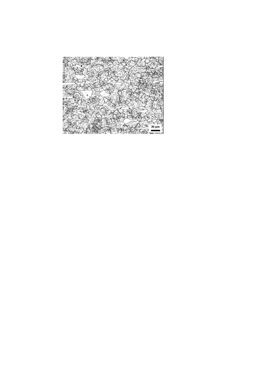
Figure 12.
Martensitic hardening structure of a hob of steel grade HS6-5-2-5 (steel number
1.3243) with insufficient tempered martensitic structure (Etchant: 3% HNO
3
.)
Grain boundary carbides.
A reduced toughness in high alloyed tool
steels will also be observed with microstructures of the type illustrated in
Fig.13. The picture shows a 40 × 40 × 20 mm
3
stamping tool made of
X153CrMoV12 grade steel (material No. 1.2379), quenched and tempered
to 61 HRC, which fractured soon after its first use. The heat treated structure
consists of an inadequately tempered martensite which additionally exhibits
carbide banding along the grain boundaries. This pattern reflects too slow
cooling in the proeutectoid carbide precipitation range between 800 and
600℃. Such carbide precipitation reduces the toughness of the material in
the grain boundary areas and will often result in intergranular fracturing
1360
6TH INTERNATIONAL TOOLING CONFERENCE
under load. No handy remedy exists in this case, since the grain boundary
carbides are virtually impossible to remove even by renewed heat treatment.
Figure 13.
Low tempered hardening structure of a blanking tool of steel grade
X153CrMoV12 (steel number 1.2379; D2-type) with carbides, layered on the grain bound-
aries (Etchant: 3% HNO
3
).
SUMMARY
The examples presented can illustrate only a small portion of the cases
documented in the failure register. However, they were selected with a view
to highlighting currently topical failure modes - specifically heat treatment
failures of the type now regularly degrading tool performance.
At the machining level, overheating during grinding operations as a result
of reduced cooling (water based grinding emulsions, minimal lubrication)
are more frequent today. In erosion machining, fusion zones resulting from
coarse erosion finishing are often a source of tool failure. Among heat treat-
ment defects, quench stress cracking deserves to be mentioned although it
occurs more frequently in large hot work tools and is largely due to design.
In tools made of high alloyed cold work and high speed steels, high retained
austenite levels and insufficiently tempered martensitic hardening structures
are a cause of concern; these phenomena often occur in conjunction with
carbide precipitation along the grain boundaries which usually reflects an

Tool Failures -Causes and Prevention
1361
insufficient quench rate in vacuum hardening processes and inadequate cool-
ing between tempering phases. Such microstructures will often form during
common hardening and tempering cycles in a vacuum hardening furnace
when the furnace is charged to full capacity. The economic benefits gained
by this process should therefore be carefully weighed against the existing
tool failure risks.
As is evident from these examples, newly launched manufacturing meth-
ods (such as grinding with minimum lubrication, erosion-machining or vac-
uum hardening) will usually give rise to new problems which may initially
have a detrimental effect on tool performance. An analysis of these cases
and the resulting findings are indispensable for making the often signifi-
cant potential of these new manufacturing methods fully accessible through
implementation of appropriate optimizing steps.
ACKNOWLEDGMENTS
We thank the following companies for their input to this publication:
BÖHLER, Düsseldorf, Edelstahlwerke Buderus AG, Wetzlar; Edelstahl Witten-
Krefeld GmbH; Schmidt + Clemens GmbH + Co and Lindlar.

1362
6TH INTERNATIONAL TOOLING CONFERENCE
Table 1.
Classification of sorts and causes of failures within the Tool Failures Register
1 sorts of failures
(a) fracture / shelly spots
(b) wear
(c) cold weld / seizing
2 failure causes
(a) design failures
i forming failures / dimensioning
ii wrong choice of material
iii wrong working hardness
(b) defects in material
i pores, shrink hole, cracks, strange inclusions
ii distribution of carbides
iii undue segregations
(c) machining failures
i bad surface quality (notch effect)
ii damages on surface (grinding failures, erosion failures)
iii welding defects (joint welding, deposit welding)
iv nitriding failures
v missing stress relieving
vi distortion
(d) heat treatment failures
i quench stress crack
ii decarburization
iii retained austenite
iv insufficient tempering stage
v coarse grain/mixed grain
vi superheating
vii precipitations on grain boundary
(e) handling failures
i mechanical overstressing
ii thermal overstressing
iii corrosive overstressing
Wyszukiwarka
Podobne podstrony:
Causes and control of filamentous growth in aerobic granular sludge sequencing batch reactors
Human Papillomavirus and Cervical Cancer Knowledge health beliefs and preventive practicies
Epidemiology and Prevention of Viral Hepatitis A to E
56 793 814 Thermal Fatique of a Tool Steel Experiment and Numerical Simulation
Causes and?fects of the French Revolution
Causes and?fects of the French Revolution
Rootkits Detection and prevention
Askildson, L Effects of Humour in the Language Classroom Humour as a Padagogical Tool in Theory and
2003 07 causes and effects
Wytyczne Centers for Disease Control and Prevention aktualiz
Einarsen (2005) The nature, causes and consequenses
w thep18 Debug It! Find, Repair, and Prevent Bugs in Your Code
The Implications of Preemptive and Preventive War Doctrines A Reconsideration
więcej podobnych podstron