
Ed-Ovations
Creating
2 DIMENSIONAL
DRAWINGS
Using
Mastercam
Activity
Guide
www.eMastercam.com
1998
Written By: Robert Holowack
Mastercam Just-In-Time Curriclum
TM

Table Of Contents
STARTING THE PROGRAM
OPENING A FILE
VIEWING A DRAWING
FITTING THE DRAWING TO THE SCREEN
ZOOMING IN ON PART OF THE DRAWING
OTHER ZOOM COMMANDS
REPAINT COMMAND
EXPLORING THE MENUS
DELETING ENTITIES
DELETING A SINGLE ENTITY
DELETING MULTILPLE ENTITIES USING "CHAIN"
DELETING MULTIPLE ENTITIES USING "WINDOW"
SELECTING MULTIPLE ENTITIES USING "POLYGON"
STARTING A NEW DRAWING
SAVING YOUR FILE
CREATING ENTITIES
CREATING RECTANGLES
CREATING LINES USING ENDPOINTS
CREATING VERTICAL & HORIZONTAL LINES
CREATING CIRCLES
CREATING ARCS
CREATING HORIZONTAL LETTERING
CREATING LETTERING ON AN ARC
CREATING A SPLINE
CREATING A SINGLE POINT
CREATING MULTIPLE POINTS
SELECTING POINTS AUTOMATICALLY
ENABLING AUTOCURSOR
PRACTICE USING AUTOCURSOR
MODIFYING ENTITIES
TRIMMING A LINE
BREAKING A LINE
JOINING TWO LINES
FILLETING
CHANGING COLORS
MOVING ENTITIES
UNDOING A MOVE RELATED COMMAND
OFFSETTING AN ENTITY
TRANSLATING AN ENTITY
MIRRORING
ENLARGING & SHRINKING ENTITIES (SCALE)
ROTATING ENTITIES
DRAGGING ENTITIES
"ON-LINE HELP" FOR DESIGNING
PRACTICE USING HELP
............ 3
............ 3
............ 4
...... 4
...... 4
...... 5
...... 5
............ 6
............ 6
...... 6
...... 7
...... 8
...... 8
............ 9
............ 9
............ 10
...... 10
...... 11
...... 12
...... 12
...... 13
...... 14
...... 15
...... 16
...... 17
...... 18
............ 19
...... 19
...... 19
............ 21
...... 21
...... 22
...... 23
...... 24
...... 25
............ 26
...... 26
...... 26
...... 28
...... 29
...... 30
...... 31
...... 32
............ 33
...... 33
Page Number
Section Title
Creating 2 DIMENSIONAL DRAWINGS Using Mastercam
Page 2 of 36
24
Activity Guide #
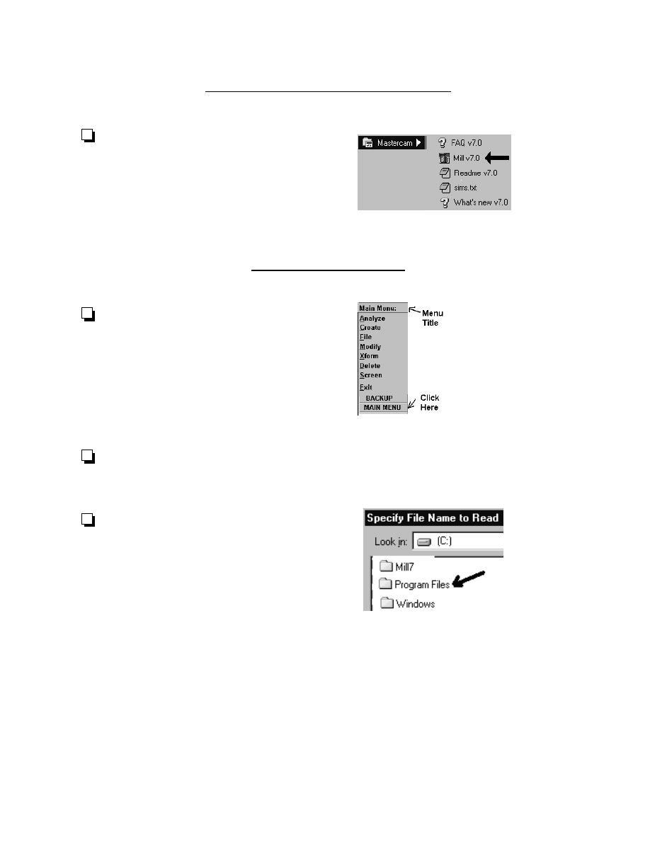
STARTING THE PROGRAM
Click on the Mastercam Version
7 Icon to start the program.
OPENING A FILE
Select MAIN MENU from the list
of commands.
The title at the top of the menu
bar should read Main Menu, if
not, keep selecting MAIN MENU
until it does.
Select FILE from the Main menu.
Select GET from the File menu.
Select the Program Files folder.
Creating 2 DIMENSIONAL DRAWINGS Using Mastercam
Page 3 of 36
24
Activity Guide #
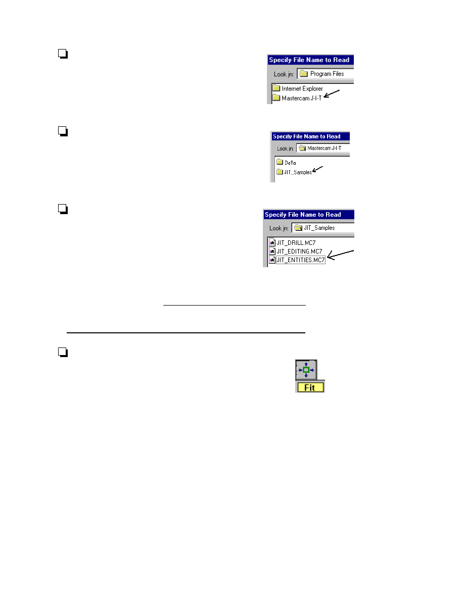
Select the " Mastercam J-I-T "
folder.
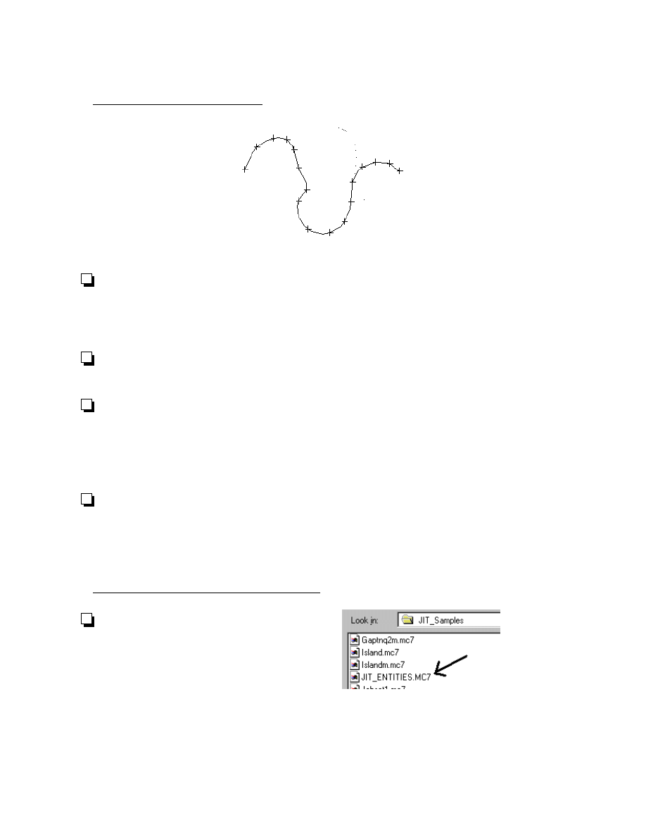
Select the JIT_Samples folder.
Select the JIT_ENTITIES.MC7
file.
Select OPEN.
FITTING THE DRAWING TO THE SCREEN
VIEWING A DRAWING
Move your mouse over each
button on the toolbar, read the
yellow flags until you find the
FIT button. Press this button, the
drawing should now fill the
screen.
Creating 2 DIMENSIONAL DRAWINGS Using Mastercam
Page 4 of 36
24
Activity Guide #
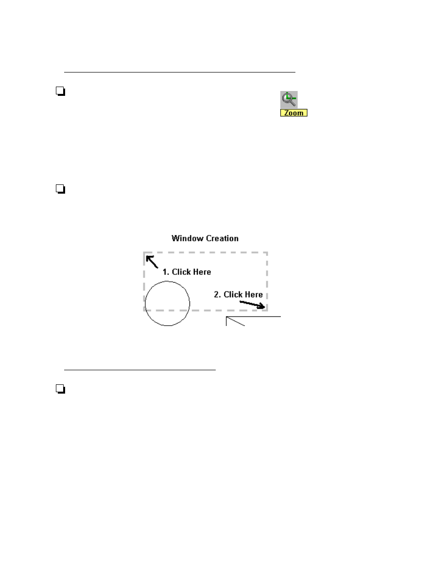
ZOOMING IN ON PART OF THE DRAWING
Move your mouse over each
button on the toolbar, reading the
yellow flag until you find the
ZOOM button. This command
allows you to zoom in on a part of
your drawing.
Click on the ZOOM button
Move the mouse cursor to a corner of the area you would like to view.
Click the left mouse button.
Move the mouse to create a window then click the left mouse button.
OTHER ZOOM COMMANDS
Experiment using the UN-ZOOM, UNZOOM by .8 , ZOOM and FIT
buttons until you are comfortable viewing all parts of the drawing.
Creating 2 DIMENSIONAL DRAWINGS Using Mastercam
Page 5 of 36
24
Activity Guide #
REPAINT COMMAND
Select the REPAINT button on
the toolbar. This will refresh your
screen with the latest information
stored in the computer.
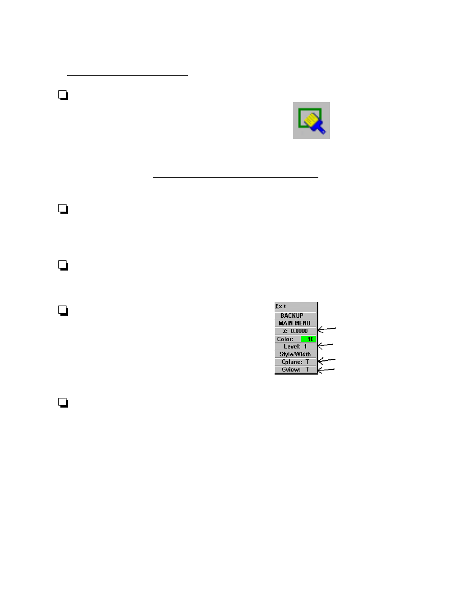
EXPLORING THE MENUS
Note the commands on the left side of the screen. They make up a
menu.
The title of each menu is displayed at the top of the command column.
Select the MAIN MENU command to move to the Main menu. Notice the
name is displayed at the top of the column.
Avoid making any changes to the
menu commands marked by the
arrows.
Try selecting different commands on the Main menu and note the
names of the different sub-menus which appear. Practice using the
BACKUP and MAIN MENU commands to move back to the Main menu
when required.
Creating 2 DIMENSIONAL DRAWINGS Using Mastercam
Page 6 of 36
24
Activity Guide #
DELETING A SINGLE ENTITY
DELETING ENTITIES
Make sure the JIT_ENTITIES.MC7 file is open.
Move to the Main Menu.
Select DELETE from the Main Menu.
Click the mouse pointer on the circle. It should disappear.
To make the circle reappear:
Select UDELETE from the Delete menu.
Select SINGLE from the Undelete menu.
Practice using the previous commands to delete and undelete the
FILLET and SPLINE entities.
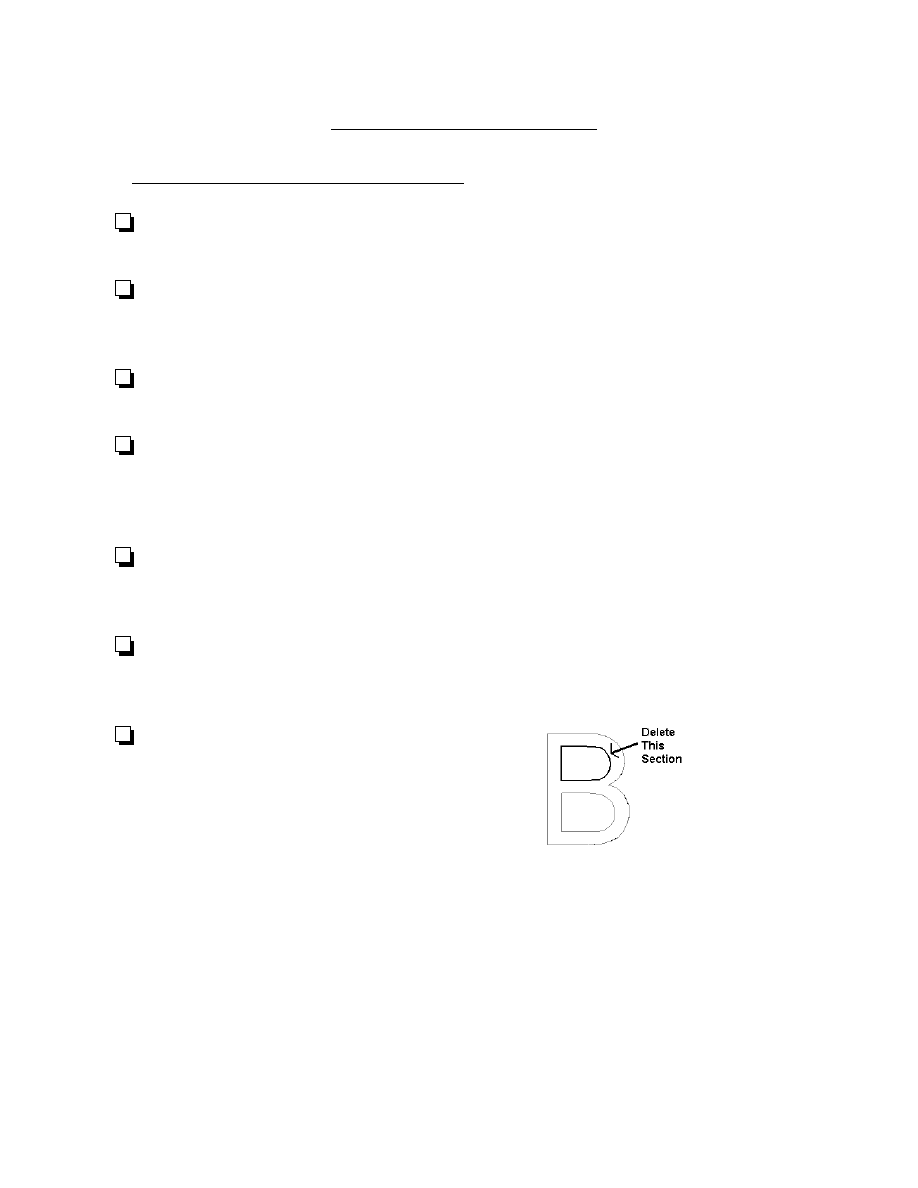
Use the ZOOM button on the toolbar to view a close up of the B in
BASIC DRAWING ENTITIES.
Use the DELETE command to
delete the portion of the B
indicated in the diagram. Notice
that only a small part of the B is
deleted with each delete
command. Use the Undelete
command to make the section of
the B reappear.
Creating 2 DIMENSIONAL DRAWINGS Using Mastercam
Page 7 of 36

24
Activity Guide #
Remove DELETING MULTILPLE ENTITIES USING "CHAIN"
Make sure the JIT_ENTITIES.MC7 file is open. This is a Read Only file
so none of the changes you make to this drawing will be saved. You can
close it and reopen the original drawing at any time.
Select DELETE from the Main menu.
Select CHAIN from the Delete menu.
Click the mouse on the desired section of the B. Note that all the entities
in the chain are now selected.
Select DONE from the Chaining menu.
To undelete the section of the B.
Select UNDELETE from the Delete menu.
Select ALL from the Undelete menu.
Select ENTITIES from the All menu.
Click on the FIT toolbar button to view the entire drawing.
Practice using the Delete command coupled with the Chain command to
delete portions of the rectangle.
DELETING MULTIPLE ENTITIES USING "WINDOW"
To delete the words BASIC DRAWING ENTITIES:
Select DELETE from the Main menu.
Select WINDOW from the Delete menu.
Create a WINDOW surrounding the lettering.
Creating 2 DIMENSIONAL DRAWINGS Using Mastercam
Page 8 of 36

24
Activity Guide #
Remove SELECTING MULTIPLE ENTITIES USING "POLYGON"
Try using the DELETE command coupled with the POLYGON
command to delete a number of different entites at once.
STARTING A NEW DRAWING
Complete the ** CO-ORDINATES In TWO DIMENSIONS **
INFORMATION BOOK.
Select MAIN MENU. This will move you to the Main menu
Select FILE from the Main menu
Select NEW from the File menu
An information box will appear that says: “Are you sure you want to
initialize geometry and operations?” ….. Select YES.
A message saying "MC7 file has changed. Save it?" may appear.
Select NO.
Select BACKUP until the Main menu is displayed.
SAVING YOUR FILE
Select FILE from the Main menu.
Creating 2 DIMENSIONAL DRAWINGS Using Mastercam
Page 9 of 36
24
Activity Guide #
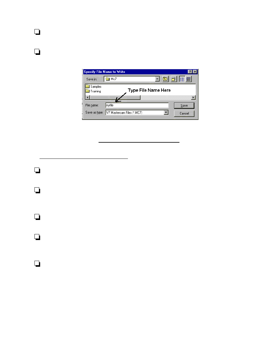
Select SAVE from the File menu.
Type in a name for your file, then select the SAVE button. You should
see the new name for your file appear at the top of the screen.
CREATING RECTANGLES
CREATING ENTITIES
Select MAIN MENU to return to the Main menu.
Select CREATE from the Main menu.
Select RECTANGLE from the Create menu.
Select 2 POINTS.
Read the text in the box in the lower portion of the screen.
It should say “Create rectangle (2): Enter the lower left corner”
Type in the X and Y co-ordinates for the lower left corner of the
rectangle.
For example: X2 Y3
Press the ENTER key. (You may not notice anything happen at this
point.)
Creating 2 DIMENSIONAL DRAWINGS Using Mastercam
Page 10 of 36
24
Activity Guide #
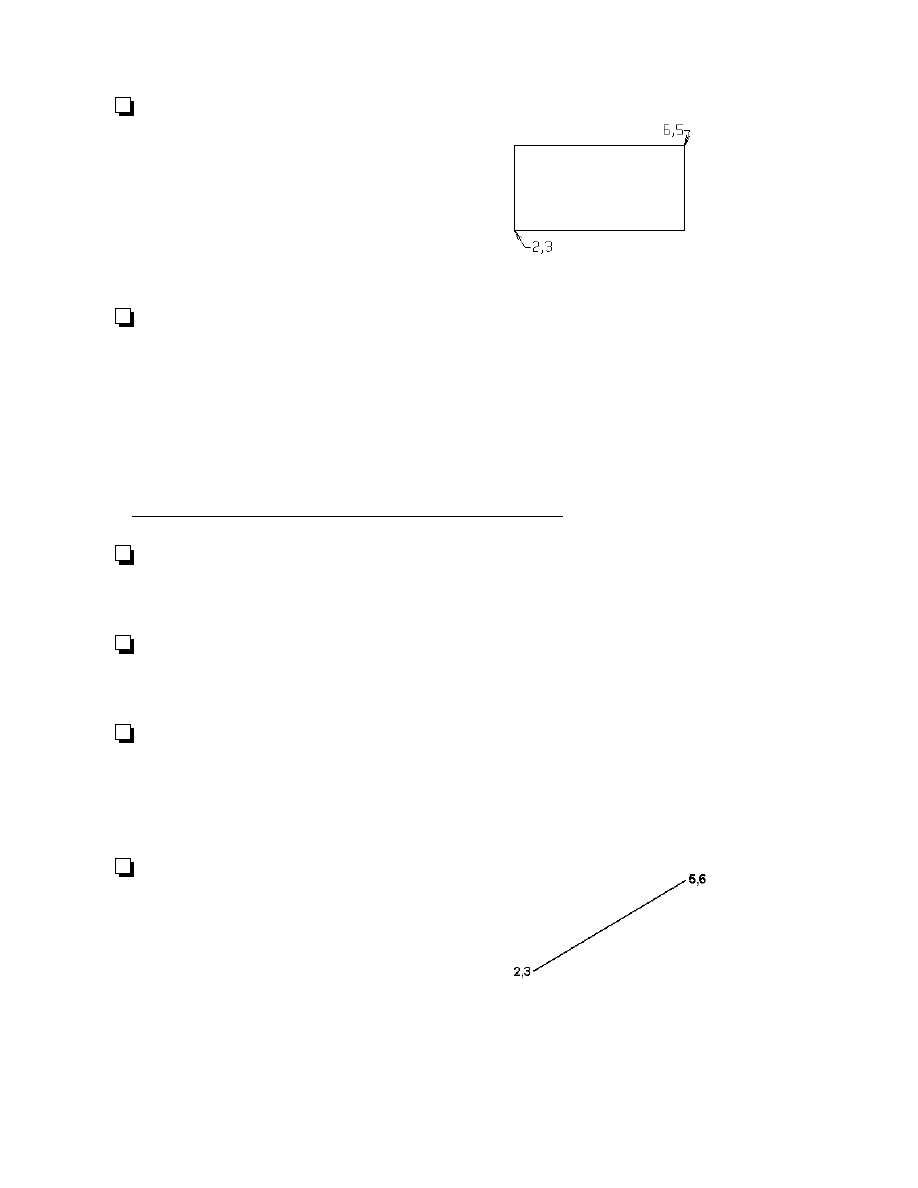
Type second set of coordinates.
For example: X6 Y5
Press ENTER.
(Use the FIT toolbar button to
view the rectangle if required.)
Practice making another rectangle, this time select 1 Point instead of 2
Point.
Type in the first co-ordinate just as you did in the previous step.
Look at the prompt below the screen, it will ask you to type in the height
and width of the rectangle.
CREATING LINES USING ENDPOINTS
Select CREATE from the Main menu.
Select LINE from the Create menu.
Select ENDPOINTS from the Line menu.
This will allow you to create a line by indicating the location of each end.
Notice the prompt at the bottom of the page is asking you to input the
first endpoint.
Type in the X and Y co-ordinates of the first endpoint. For example X2
Y3.
Type in the X and Y co-ordinates
of the second endpoint.
For example X5 Y6.
Creating 2 DIMENSIONAL DRAWINGS Using Mastercam
Page 11 of 36

24
Activity Guide #
Practice creating a few more lines until you are comfortable using the
LINE and ENDPOINTS commands.
remove CREATING VERTICAL & HORIZONTAL LINES
Select CREATE from the Main menu.
Select LINE from the Create menu.
Select VERTICAL from the Line menu.
Type in a co-ordinate for one end of the line. For example X3 Y4
Notice that as you move the mouse pointer up or down the line will
follow it. Click the mouse to finish creating the line.
Follow the same procedure to create a horizontal line.
Practice creating Horizontal and Vertical lines until you are comfortable
with the commands.
CREATING CIRCLES
Creating 2 DIMENSIONAL DRAWINGS Using Mastercam
Page 12 of 36
24
Activity Guide #
Select CREATE from the Main menu.
Select ARC from the Create menu.
Select CIRC PT + RAD from the Arc menu.
Notice the prompt at the base of the screen asks you to enter a center
point for the circle. Type in the co-ordinates of the center, for example
X2 Y2
Now the prompt says: "Enter the radius"
Type in a value for the radius of the circle. For example 2
Practice using the circle command until you are comfortable making
circles of different sizes in different locations.
CREATING ARCS
Select CREATE from the Main menu.
Select ARC from the Create menu.
Select ENDPOINTS from the Arc menu.
The prompt at the base of the screen says: "Enter the first end point"
Type the co-ordinates of the first end point. For example: X1 Y1
Creating 2 DIMENSIONAL DRAWINGS Using Mastercam
Page 13 of 36
24
Activity Guide #
The prompt at the base of the screen says: "Enter the second end point"
Type co-ordinates of the second end point. For example: X1 Y4
The prompt at the base of the screen says: "Enter the radius"
Type in the value for the radius of the arc. For example: 6
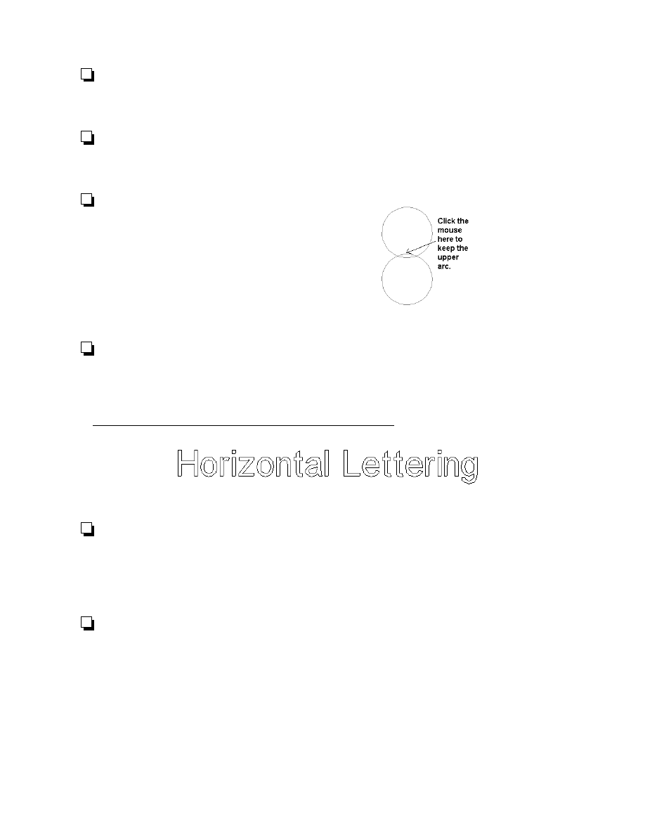
You will now see two circles
overlapping. Click the mouse on
the upper circle to keep the
upper arc.
Practice making arcs until you are comfortable using the commands.
CREATING HORIZONTAL LETTERING
Select CREATE from the Main menu.
Select NEXT MENU from the Create menu.
Select LETTERS
Select TRUE TYPE(R) from the Letters By: menu.
You should see a dialogue box which will allow you to select the font
type and style of the letters. (The font size setting is not used by
Mastercam.)
Select OK.
Creating 2 DIMENSIONAL DRAWINGS Using Mastercam
Page 14 of 36
24
Activity Guide #
Type your message.
Press ENTER.
Type in the value for the height of the letters. (1 equals one inch)
Press ENTER
Select HORIZONTAL from the Direction Menu.
The prompt at the base of the screen should say "Enter Letter Spacing"
Press ENTER to select the default letter spacing.
Click the mouse anywhere on the screen and the letters should appear.
Practice creating Horizontal and Vertical lettering of different types and
sizes until you are comfortable using the commands.
Remove CREATING LETTERING ON AN ARC
Select CREATE from the Main menu.
Select NEXT MENU from the Create menu.
Select LETTERS
Select TRUE TYPE(R) from the Letters By: menu.
Creating 2 DIMENSIONAL DRAWINGS Using Mastercam
Page 15 of 36

24
Activity Guide #
Select the font type and style of the letters.
Select OK.
Type your message.
Press ENTER.
Type in the value for the height of the letters. For example .5
Press ENTER
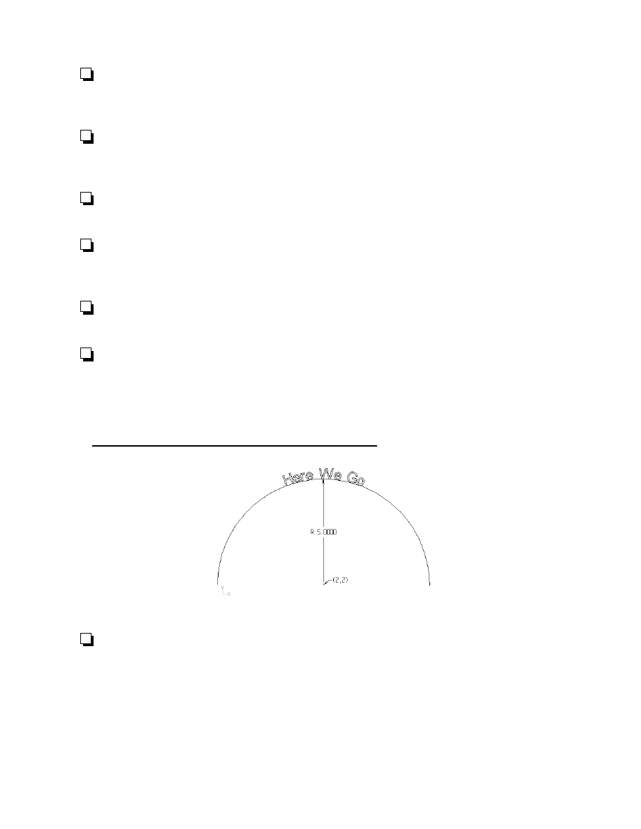
Select TOP OF ARC from the Direction menu.
Press ENTER to select the default letter spacing.
Note that the prompt at the base of the screen says: "Enter Co-
ordinates Of Arc Center"
Type in an X Y value. For example X2 Y2
The prompt should now read: "Enter Arc Radius"
Type in a value. For example 5.
Press ENTER.
The lettering should now appear
as shown.
Practice creating lettering on the top and bottom of arcs until you are
comfortable using the commands.
Creating 2 DIMENSIONAL DRAWINGS Using Mastercam
Page 16 of 36
24
Activity Guide #
Remove CREATING A SPLINE
Select CREATE from the Main menu.
Select SPLINE from the Create menu.
Select MANUAL from the Spline menu.
Make sure that SKETCH is selected from the Point Entry menu.
Click the mouse in a number of locations on screen, you should notice a
free form curve that travels through each point you create with the
mouse.
Click the ESC key when the spline is complete.
Practice making a few more splines until you are comfortable working
with the commands.
CREATING A SINGLE POINT
Select the JIT_ENTITIES.MC7
file.
Select OPEN.
Creating 2 DIMENSIONAL DRAWINGS Using Mastercam
Page 17 of 36
24
Activity Guide #
Select CREATE from the Main menu.
Select POINT from the Create menu.
Select POSITION from the Point menu.
The prompt should now read: "specify a point"
Select CENTER from the Point Entry menu.
(You are now ready to select the center of a circle or arc during the
next step.)
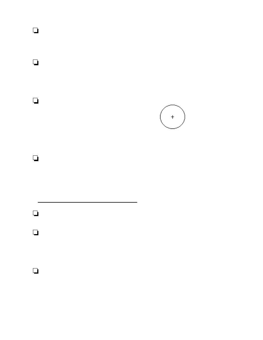
The prompt should now read:
"Select an arc".
Use the mouse to select the
purple circle.
The point should appear in the
center of the circle as shown to
the right.
Try creating another point at the lower right hand corner of the rectangle.
To do this you will need to use the INTERSEC command when you get
to the Point Entry menu.
Remove CREATING MULTIPLE POINTS
Be sure the JIT_ENTITIES.MC7 file is open.
Select CREATE from the Main menu.
Select POINT from the Create menu.
Select ALONG ENT from the Point menu. (ALONG ENT stands for
along entity)
The prompt should now read: "Select an entity".
Use the mouse to select the blue line.
Creating 2 DIMENSIONAL DRAWINGS Using Mastercam
Page 18 of 36
24
Activity Guide #
The prompt should now read:
"Enter number of points to create"
Type in a number, for example 5.
Press ENTER.
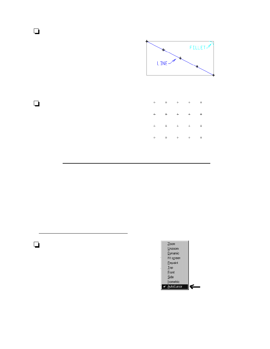
You should see points appear
along the line as shown to the
right.
Try creating a new set of points.
This time in a grid pattern similar
to those shown on the right.
To do this you will need to select
GRID when you get to the Point
menu.
remove SELECTING POINTS AUTOMATICALLY
As you have probably noticed there are many instances when you need
to select a specific point, for example the Endpoint of a line or the
Centerpoint of a circle. Mastercam provides the Autocursor tool to select
these points automatically.
ENABLING AUTOCURSOR
Position the mouse pointer in the
drawing area and click the right
mouse button.
Select AUTOCURSOR from the
drop down list.
Creating 2 DIMENSIONAL DRAWINGS Using Mastercam
Page 19 of 36
24
Activity Guide #
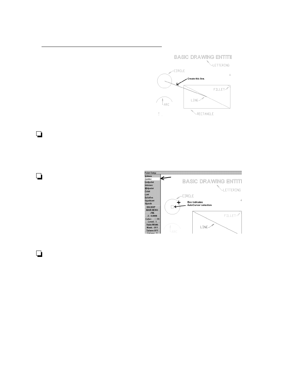
PRACTICE USING AUTOCURSOR
To help you become familiar with
AutoCursor you will use it to draw
a line between the center of the
Circle and the Midpoint of the
blue diagonal line. As shown to
the right.
Be sure the JIT_ENTITIES.MC7 file is open.
Select CREATE from the Main menu.
Select LINE from the Create menu.
Select ENDPOINTS from the Line menu.
Move the mouse pointer to the
edge of the circle.
Notice that a small square
appears at the center of the circle
and "Center" is highlighted in the
Point Entry menu. AutoCursor
has selected the center of the
circle.
Click the mouse to start the line.
Move the mouse from one end of the blue diagonal line to the other.
Notice that the square moves from endpoint to midpoint and back to
endpoint as the mouse is moved, the appropriate menu item is also
highlighted.
Click the mouse when the square is on the midpoint to complete the line.
Creating 2 DIMENSIONAL DRAWINGS Using Mastercam
Page 20 of 36
24
Activity Guide #
CAUTION !!
Most of the time AutoCursor is a handy tool but there may be times
when you need to turn it off and select a point using the menus.
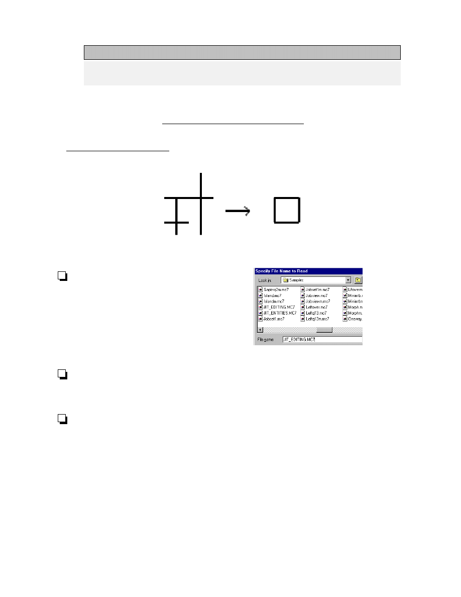
TRIMMING A LINE
MODIFYING ENTITIES
Open the file JIT_EDITING.MC7
in the JIT_Samples folder
Use the ZOOM command to get a close up view of the figure marked
Trim in the lower left area of the drawing area.
Trim the yellow line to the red line by following the instructions below.
Select MODIFY from the Main menu.
Select TRIM from the Modify menu.
Select 1 ENTITY from the Trim menu.
Creating 2 DIMENSIONAL DRAWINGS Using Mastercam
Page 21 of 36

24
Activity Guide #
Notice that the prompt now reads: Trim (1) Select the entity to trim
Use the mouse to select the yellow line, but be sure you click to the right
of the red line. (You always select the part of the line you would like to
keep.)
Notice that the prompt now reads: Trim (1) Select the entity to trim to
Use the mouse to select the red line.
The yellow line should be trimmed back to the red line.
Trim the yellow and green lines by following the instructions below.
Select MODIFY from the Main menu.
Select TRIM from the Modify menu.
Select 2 ENTITIES from the Trim menu.
Notice that the prompt now reads: Trim (2) Select the entity to trim
Select the green line. (Be sure to click on the section of the line you
would like to keep.)
Notice that the prompt now reads: Trim (2) Select the entity to trim to.
Select the yellow line. (Be sure to click on the section of the line you
would like to keep.)
Both the lines should be trimmed to form a 90 degree corner.
Extend the blue line to meet the green line by following the instructions
below.
Select 1 ENTITY from the Trim menu.
Select the blue line.
Select the green line.
You should see the blue line extend to touch the green line.
Use the Trim command on the red and blue lines to produce a square.
Go to the JIT_Samples folder and Open the JIT_EDITING.MC7 file.
Trim the lines as before but this time try not to use the instructions.
Creating 2 DIMENSIONAL DRAWINGS Using Mastercam
Page 22 of 36
24
Activity Guide #
BREAKING A LINE
Make sure the JIT_EDITING.MC7 file is open.
Use the ZOOM command to view the box labeled Break in the upper
left corner of the drawing.
Break the yellow line into two parts by following the directions below.
Select BREAK from the Modify menu.
Select 2 PIECES from the Break menu.
Notice the prompt reads: Break (2) Select an entity.
Select the yellow line.
The prompt now reads: "Enter the breakpoint."
Select INTERSEC from the Point Entry menu.
(This indicates that you would like to pick a point where two lines
intersect.)
Notice the prompt now reads:
"Select a line arc or spline."
Select the lines shown in the
diagram on the right.
It will appear as though nothing has happened but the yellow line is now
two separate pieces.
You can test this by attempting to delete the line. Only part of it should
disappear.
Creating 2 DIMENSIONAL DRAWINGS Using Mastercam
Page 23 of 36

24
Activity Guide #
remove JOINING TWO LINES
Make sure the JIT_EDITING.MC7 file is open.
Use the ZOOM command to view the the box labeled "Join" in the
upper right corner of the drawing.
Join the yellow line to the red line by following the directions below.
Select JOIN from the Modify menu.
Notice the prompt now reads: "Join: Select a entity."
Select the yelllow line.
Select the red line.
The entire line should turn yellow indicating that it is now one entity
instead of two.
FILLETING
Make sure the JIT_EDITING.MC7 file is open.
Use the ZOOM command to view the the box labeled "Fillet" in the
lower right corner of the drawing.
Fillet the corner of the yellow and red lines by following the directions
below.
Select FILLET from the Modify menu.
There should be a red "Y" beside the Trim menu option. (If not, select
TRIM)
Creating 2 DIMENSIONAL DRAWINGS Using Mastercam
Page 24 of 36
24
Activity Guide #
Select RADIUS from the Fillet menu.
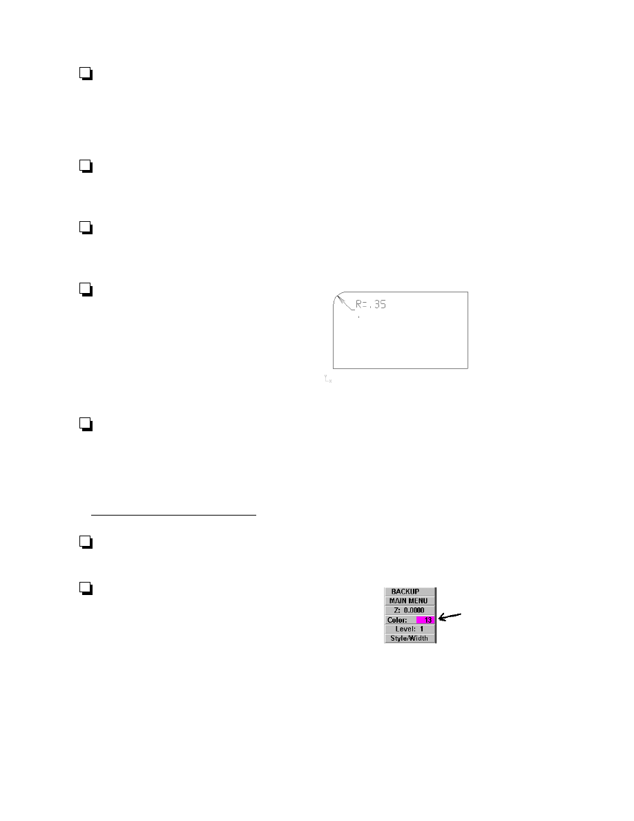
The prompt now reads: "Enter the fillet radius:"
Type a value for the radius. For example: .35
Press ENTER.
The lower line of the prompt should now read: "Select an entity"
Select the red line.
The prompt should now read: " Fillet: Select another entity"
Select the yellow line.
The corner of the lines should
now be filleted as shown.
Practice filleting the other corners of the rectangle. Try using different
values for the radius. Also, try turning the Trim option to N.
CHANGING COLORS
Make sure the JIT_EDITING.MC7 file is open.
Select the Color Command as
shown.
Creating 2 DIMENSIONAL DRAWINGS Using Mastercam
Page 25 of 36

24
Activity Guide #
Select a color from the chart.
Select OK.
Select SCREEN from the Main menu.
Select CHG COLORS from the Screen menu.
Select a line on the drawing.
You should see it change to the selected color.
Practice changing the color of other lines on the drawing.
UNDOING A MOVE RELATED COMMAND
MOVING ENTITIES
Holding down the ALT key and pressing U will undo the move
command. Try using this command to undo some of the moves made in
the next sections.
OFFSETTING AN ENTITY
Open the file JIT_MOVING.MC7 in the JIT_Samples folder
Zoom in on the box labeled Offset in the lower left corner.
Select XFORM from the Main menu.
Select OFFSET from the Xform menu.
Creating 2 DIMENSIONAL DRAWINGS Using Mastercam
Page 26 of 36
24
Activity Guide #
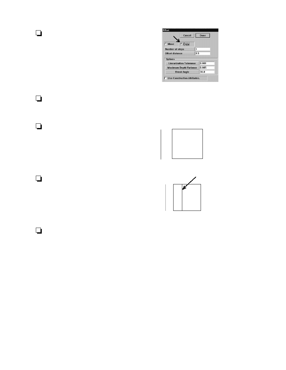
Turn the copy option on.
Set number of steps to 1.
Set offset distance to 0.5
Select DONE
Notice the prompt reads: "Select the line, arc, curve or spline to offset."
Click the mouse on the yellow line.
Click the mouse on the area just
to the left of the yellow line.
You should see a line appear as
shown on the right.
Repeat the previous steps but
this time click on the area to the
right of the yellow line. You
should see a line appear as
shown to the right.
Experiment by changing the
Move / Copy Option,
Number of Steps
Offset Distance
while you offset the other lines in the drawing.
Creating 2 DIMENSIONAL DRAWINGS Using Mastercam
Page 27 of 36
24
Activity Guide #
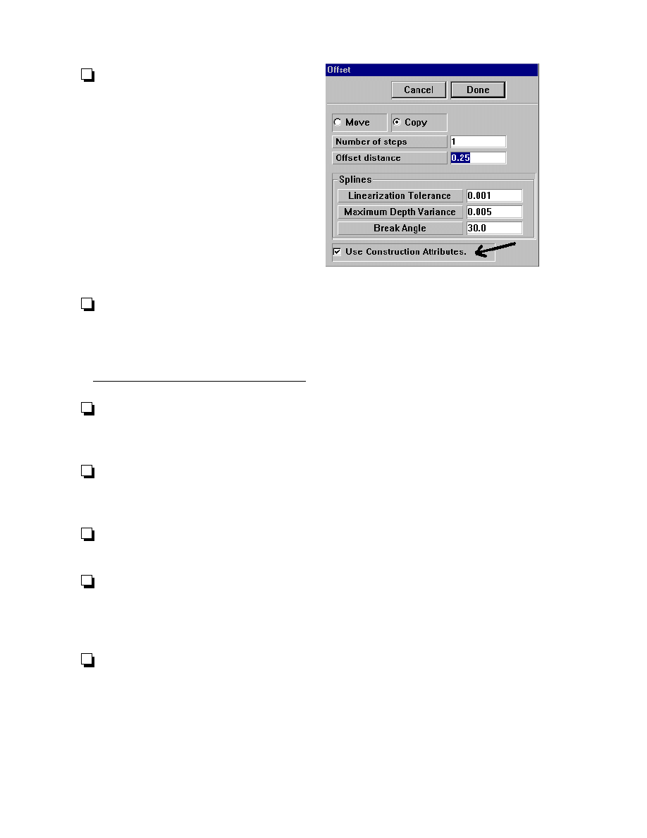
Select the "Use Construction
Attributes" box. (This will cause
the offset lines to be drawn using
the currently selected drawing
color.)
Try offseting a couple more lines. Notice the color of the new lines.
TRANSLATING AN ENTITY
Open the file JIT_MOVING.MC7 in the JIT_Samples folder
Zoom in on the box labeled Translate in the upper left corner.
Select XFORM from the Main menu.
Select TRANSLATE from the Xform menu.
Select CHAIN from the Select Entities menu.
Use the mouse to select the RED circle, then select the small square.
Select DONE to finish chaining
Select DONE again to finish selecting entities.
Select BETWEEIN PTS from the Translation Direction menu.
Creating 2 DIMENSIONAL DRAWINGS Using Mastercam
Page 28 of 36
24
Activity Guide #
The prompt now reads: "Enter
the point to translate from"
(The following commands will
select the center point of the
small circle.)
Select CENTER from the Point
Selection menu.
Use the mouse to select the
small circle.
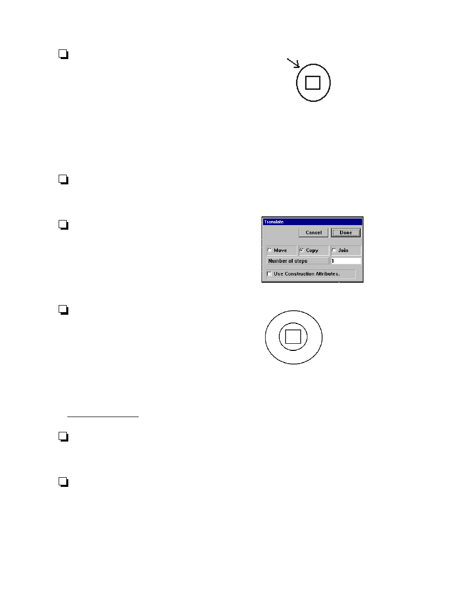
Select CENTER from the Point Selection menu.
Use the mouse to select the large yellow circle.
Select the COPY option in the
dialogue box.
Select DONE.
You should see the circle and
square translated to the center of
the large circle.
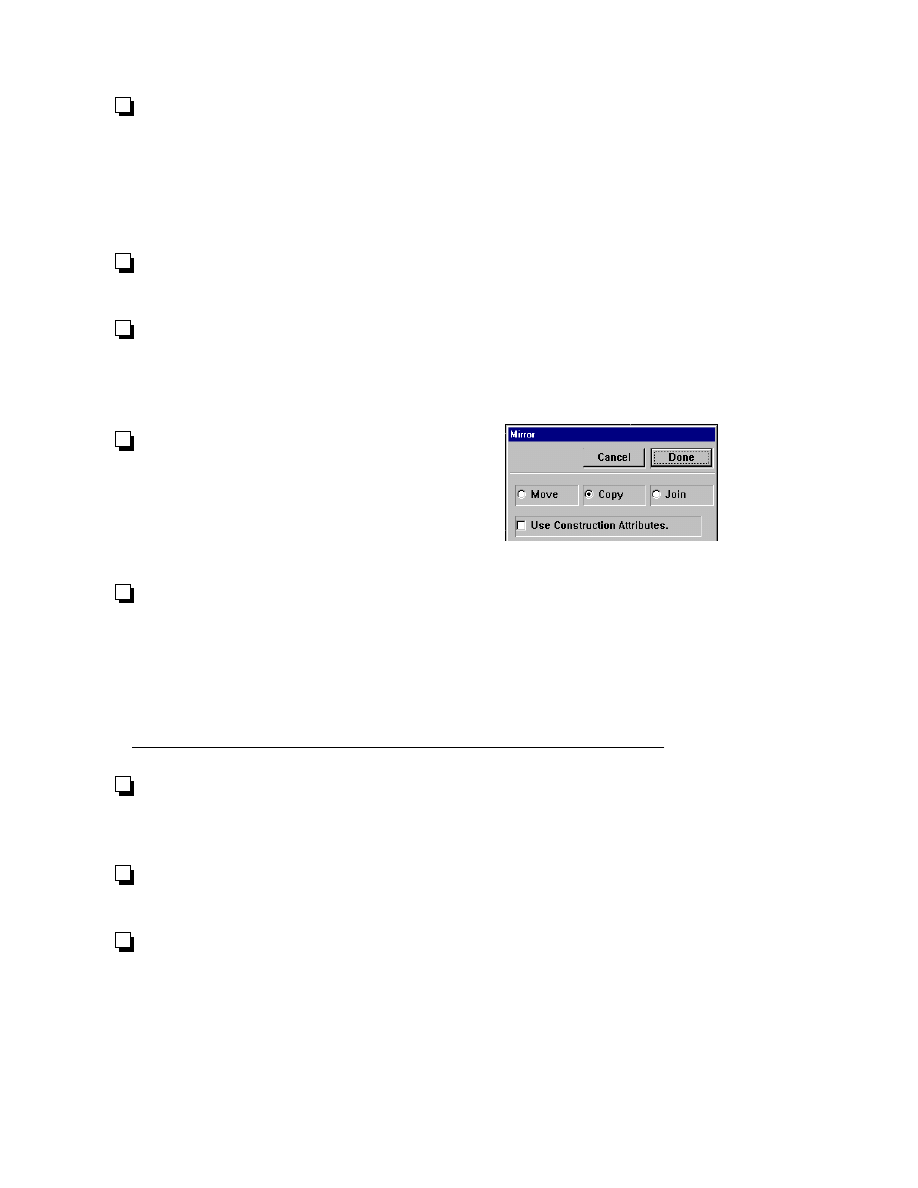
MIRRORING
Open the file JIT_MOVING.MC7 in the JIT_Samples folder
Zoom in on the box labeled Mirror in the upper right corner.
Select XFORM from the Main menu.
Select MIRROR from the Xform menu.
Creating 2 DIMENSIONAL DRAWINGS Using Mastercam
Page 29 of 36
24
Activity Guide #
Select POLYGON from the Translate menu.
Use the mouse to create a multi-sided figure which surrounds only the
letter E.
Select DONE to complete the polygon creation.
The letter E should be selected.
Select DONE to complete the entity selection process.
Select LINE from the Mirror menu.
The prompt now reads: "Select a line about which to mirror"
Use the mouse to click on the green line.
Make sure the Copy option is
selected in the dialogue box.
Select DONE.
Hold down the ALT key then press the U key. This will undo the mirror
action.
Try to repeat the mirror procedure on your own.
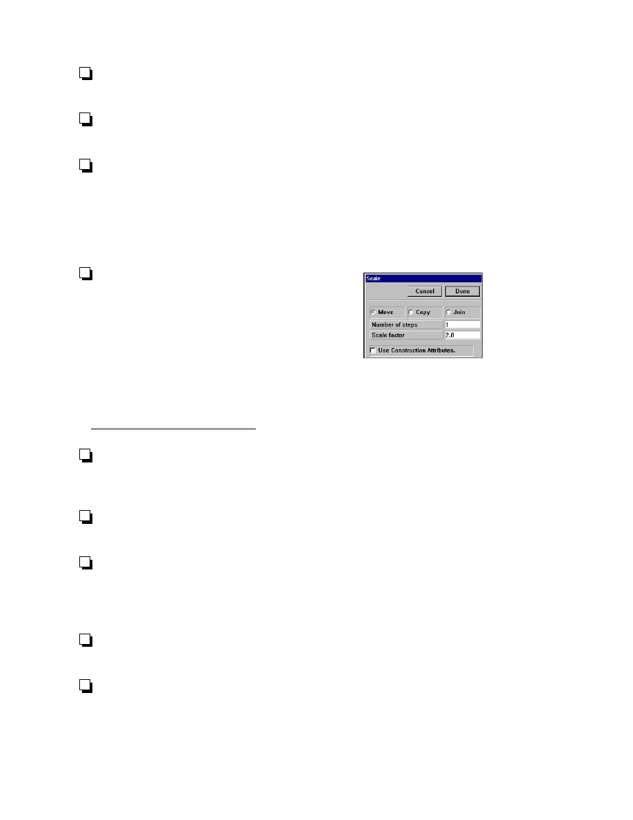
remove ENLARGING & SHRINKING ENTITIES (SCALE)
Open the file JIT_MOVING.MC7 in the Samples folder
Zoom in on the box labeled Scale in the lower section of the drawing.
Select SCALE from the Xform menu.
Select WINDOW from the scale menu.
Use the mouse to create a window around the red and yellow figure.
Creating 2 DIMENSIONAL DRAWINGS Using Mastercam
Page 30 of 36
24
Activity Guide #
Select DONE to complete the entity selection process.
Select POINT from the Scale About menu.
Notice the prompt reads: "Enter the point to scale about."
Use the following commands to pick the point where the two yellow lines
cross.
Select INTERSEC from the Point Entry menu.
Select one of the crossing lines, then select the other.
Setting the options in the
dialogue box as shown will
double the size of the object. If
you select Copy instead of Move
the original object will still be in
place.
remove ROTATING ENTITIES
Open the file JIT_MOVING.MC7 in the JIT_Samples folder
Zoom in on the box labeled Rotate in the lower right corner.
Select ROTATE from the Xform menu.
Select CHAIN from the Rotate menu.
Use the mouse to select a section of the yellow letter T.
Select DONE to complete the chaining process.
Select DONE to complete the entity selection process.
Select POINT from the Rotate About menu.
Creating 2 DIMENSIONAL DRAWINGS Using Mastercam
Page 31 of 36
24
Activity Guide #
Use the following commands to select the center point of the green
circle.
Select CENTER from the Point Entry menu.
Use the mouse to select the green circle.
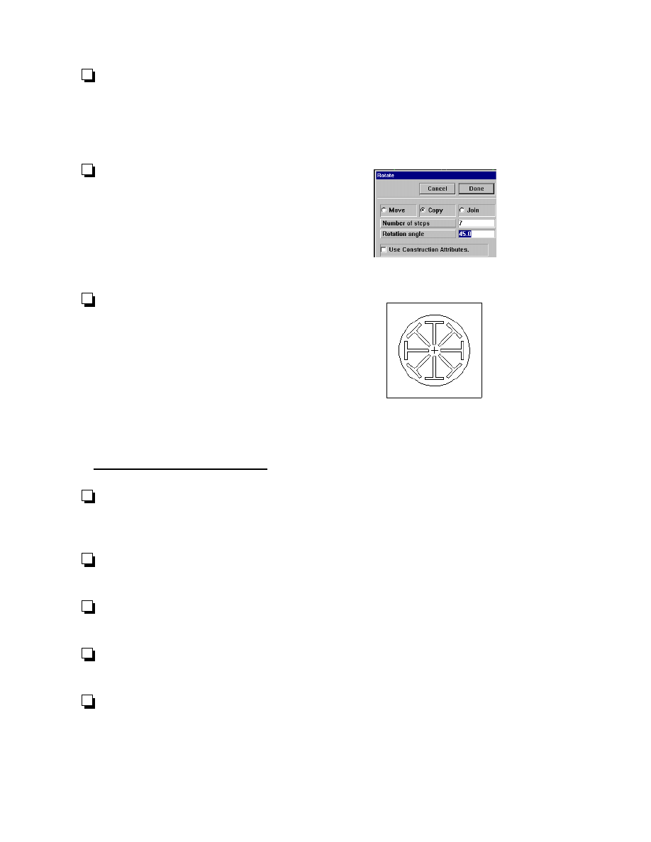
Ensure that the Copy option in
the dialogue box is turned on.
Enter 7 for the number of steps.
Enter 45.0 for the rotation angle.
Select DONE
You should see a result similar to
the diagram.
Practice using the rotate
command with different values
for the Step and Degree settings.
DRAGGING ENTITIES
Open the file JIT_MOVING.MC7 in the JIT_Samples folder
Zoom in on the box labeled Drag in the lower section of the drawing.
Select MODIFY from the main menu.
Select DRAG from the Modify menu.
Select TRANSLATE from the Drag menu.
Select WINDOW from the Drag: Select Geometry menu.
Creating 2 DIMENSIONAL DRAWINGS Using Mastercam
Page 32 of 36

24
Activity Guide #
Create a window around the red,yellow and green figure.
Select DONE to end the geometry selection process.
Notice the prompt reads: "Drag: enter the starting point.
Select ENDPOINT from the Point Selection menu.
Select the lower left corner of the figure.
As you move the mouse you will notice the figure move with it.
Press the R key, this will cause the figure to rotate rather than traslate.
Pressing the T key will change back to translation.
Click the mouse to end the operation and leave the object in that
position.
Practice using the Drag command until you are comfortable rotating and
placing ojects. Try setting the copy option in the Drag menu to "Y", this
will leave the original object in place.
"ON-LINE HELP" FOR DESIGNING
Mastercam provides an extensive system of "On-Line Help" which can
be accessed by pressing the "ALT + H " keys. Most of the help is
context sensitive which means help is provided related to the highlighted
command or menu. This is a quick method for refreshing your memory
on a certain procedure or doing further research about available options.
Creating 2 DIMENSIONAL DRAWINGS Using Mastercam
Page 33 of 36
24
Activity Guide #
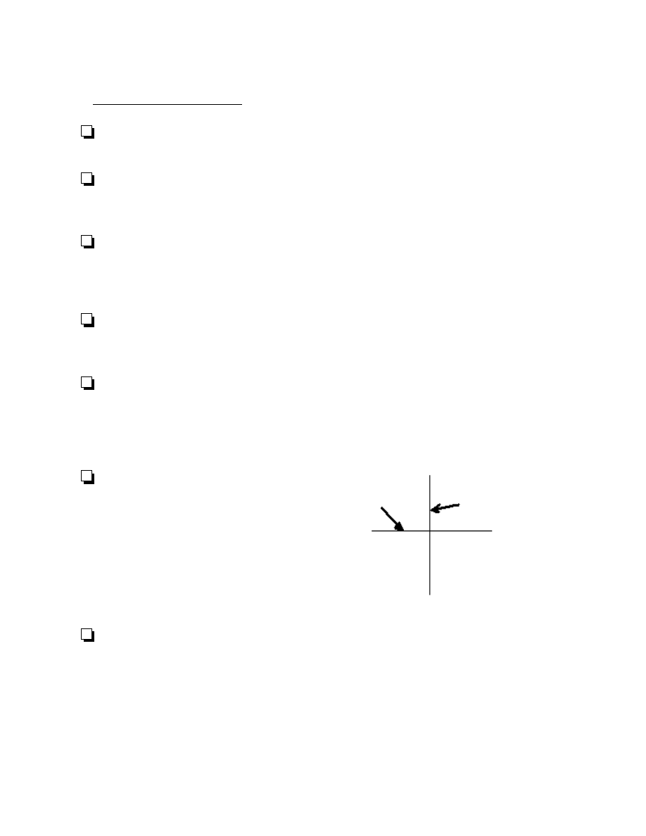
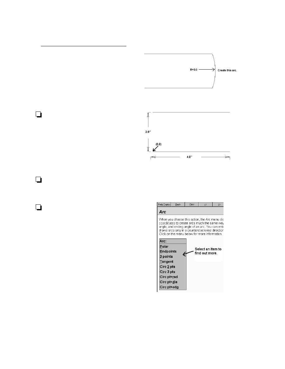
PRACTICE USING HELP
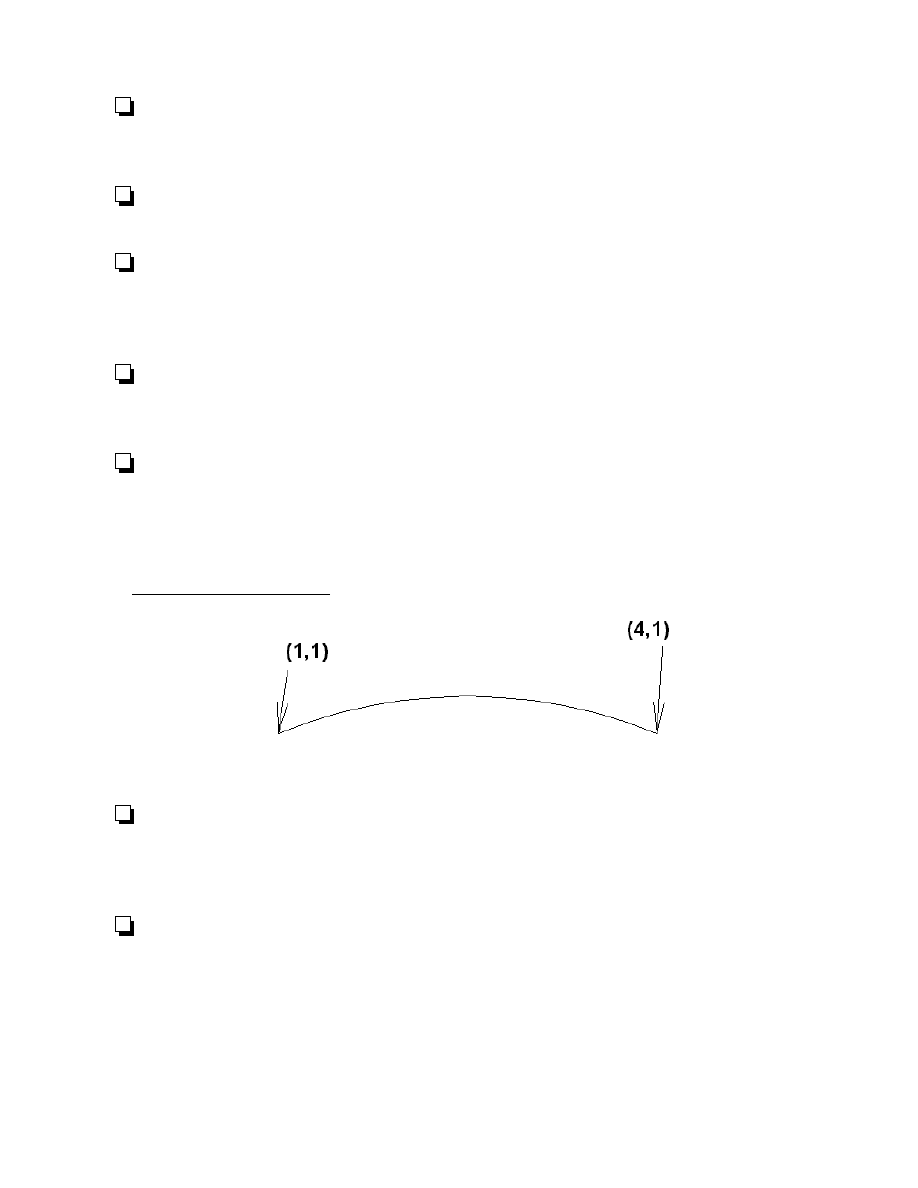
This section will provide you with
some experience using On-Line
Help while creating the arc
shown in the diagram.
Create the lower horizontal line
as shown in the diagram.
Translate the line upward by 2.0"
Select CREATE from the Main menu.
Select ARC from the Create menu.
Hold down the "ALT" key and
press "H". You will see a help
screen like the one shown.
Explore the items from the menu
to determine which of the options
you will need to create your arc.
Creating 2 DIMENSIONAL DRAWINGS Using Mastercam
Page 34 of 36
24
Activity Guide #
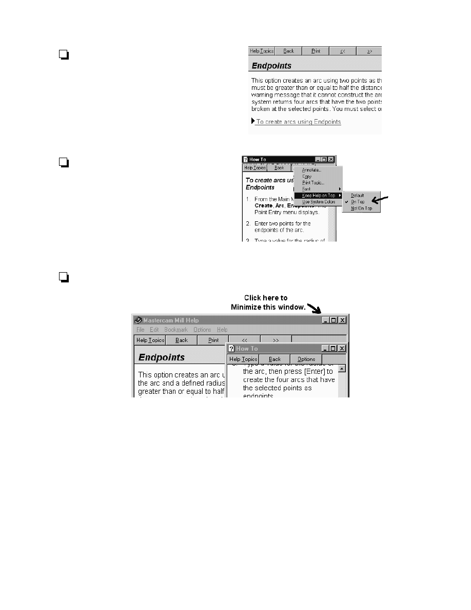
You should have found that the
Endpoints option was the one
you needed. Read the text, then
click on the green text at the
bottom of the screen.
You will see a "How To" box
with instructions for creating an
arc using endpoints.
Select OPTIONS then select ON
TOP, this will keep the "How To"
box on top of the Mastercam
window.
Minimize the larger help window by selecting the box shown below.
Creating 2 DIMENSIONAL DRAWINGS Using Mastercam
Page 35 of 36
24
Activity Guide #
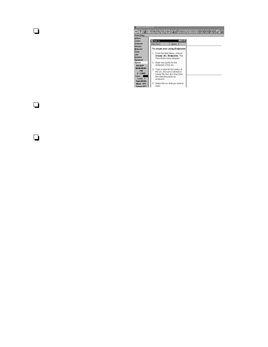
Select the REPAINT toolbar
button to refresh the screen.
Drag the "How To" box to the
location shown.
Select the REPAINT toolbar button to refresh the screen.
Follow the instructions in the "How To" box to create the arc. Close the
"How To" box when the arc is complete.
Take a few minutes to explore the On-Line Help related to other
commands.
Creating 2 DIMENSIONAL DRAWINGS Using Mastercam
Page 36 of 36
Wyszukiwarka
Podobne podstrony:
LuchykV Problems of creation id Nieznany
jedi master yoda(1) id 227107 Nieznany
Some human dimensions of computer virus creation and infection
Creativy and Personal Mastery
Gor±czka o nieznanej etiologii
Abolicja podatkowa id 50334 Nieznany (2)
45 sekundowa prezentacja w 4 ro Nieznany (2)
4 LIDER MENEDZER id 37733 Nieznany (2)
Mechanika Plynow Lab, Sitka Pro Nieznany
katechezy MB id 233498 Nieznany
2012 styczen OPEXid 27724 Nieznany
metro sciaga id 296943 Nieznany
Mazowieckie Studia Humanistyczn Nieznany (11)
cw 16 odpowiedzi do pytan id 1 Nieznany
więcej podobnych podstron