
GENERAL
This section has the instructions that are neces-
sary for correct periodic maintenance. Periodic
maintenance is a program that includes periodic
inspection and lubrication. This section is divided
into two parts: Maintenance Schedule and Main-
tenance Procedures. The Maintenance Schedule
has the maximum time intervals between mainte-
nance checks. The Maintenance Procedures has
the instructions or additional information for do-
ing some of the maintenance checks.
MOVING A DISABLED LIFT
TRUCK
This lift truck is not normally towed. If the trac-
tion system will not operate, make repairs at the
location if possible. If the lift truck must be moved,
do not lift it by connecting chains to the overhead
guard. The lift truck can be lifted by using an-
other lift truck. Make sure the other lift truck has
the capacity to lift the total unit weight listed on
the nameplate. Make sure to add the weight of the
battery if the battery will be lifted. The lift truck
used to lift the disabled truck, must have the ca-
pacity at a load center equal to half the width of
the lift truck being lifted. Put the other lift truck in
position to balance the disabled lift truck. Make
sure the forks are long enough to support the full
width of the unit. Be careful to put the forks in a
position to prevent damage. If the disabled truck
has wire guidance do not damage the sensors.
CAUTION
NEVER attempt to tow the lift truck by
fastening any towing device to the at-
tachment.
If the lift truck must be towed, lift the motor com-
partment so that the drive wheel does not touch
the floor and the motor compartment is against
the stop. Fasten the motor compartment to keep it
in the raised position. To tow the truck, carefully
fasten the chain to the caster end. Make sure the
chain is fastened so that the chain will not cause
damage. Travel slowly and do not tow on a grade.
INTRODUCTION
CAUTION
Put a tag in the operator’s compartment
stating - DO NOT OPERATE.
RAISING THE R3OCH
It is necessary to raise the lift truck to change the
drive wheel, load wheels or casters. Raise the base
arm or motor compartment only enough to permit
removal of the wheel or caster. Put blocks under
the base arm or under the edge of the plates of the
motor compartment assembly. Make sure the lift-
ing device has a capacity of at least two thirds the
weight of the truck plus battery. See the name-
plate for truck and battery weights.
WARNING
Raise the lift truck only if it is on a solid
level floor. Make sure that the blocks
can hold the weight. Do not make a stack
of blocks. Use a larger block. Put a block
at the other wheels to prevent movement
of the lift truck.
CAUTION
Make sure the sensors are not damaged
on trucks that have wire guidance.
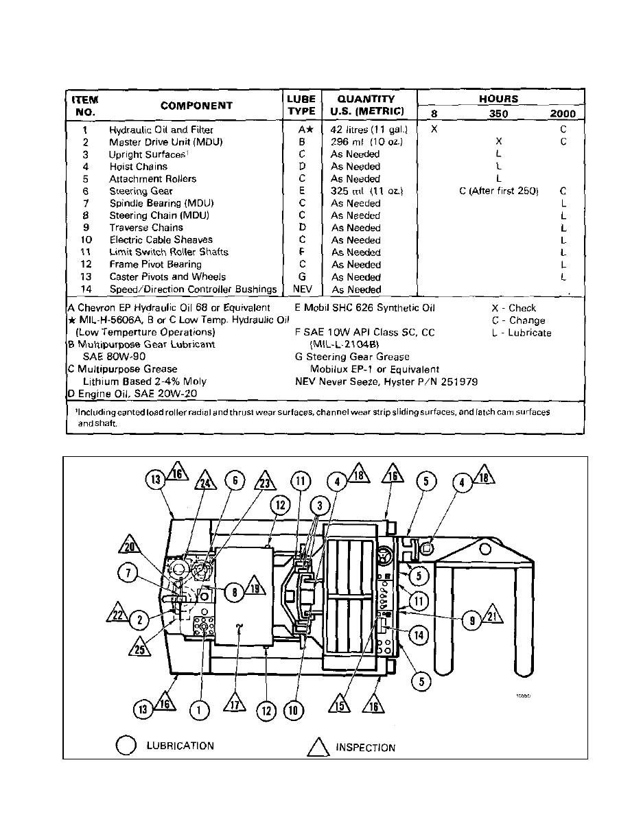
MAINTENANCE SCHEDULE
The Maintenance Schedule gives the maintenance
interval in operating hours as shown on the
hourmeter. The table for the Maintenance Sched-
ule has two schedules, the hour schedule and the
periodic schedule. If the lift truck is operated more
than eight hours each day, the hour schedule must
be used. If the lift truck is operated less than eight
hours each day, the periodic schedule can be used.
The following chart shows the location of the lu-
brication and inspection items.
CAUTION
The maintenance schedules are made
according to the maximum service in-
tervals for average conditions. If the
operation is not average, more frequent
inspection and lubrication is needed.
LUBRICATION
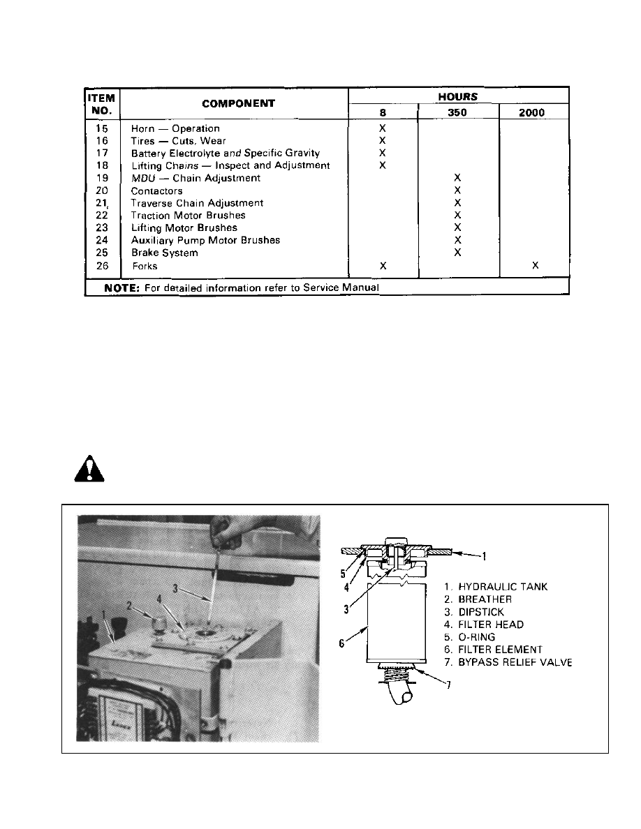
FIGURE 1. HYDRAULIC OIL AND FILTER
NOTE
Item references are the item numbers
in the maintenance schedule table and
the diagram.
WARNING
Disconnect the battery before opening
the electrical compartment doors and
during service.
HYDRAULIC OIL AND FILTER
(Item 1) (See Figure 1)
Make sure the temperature of the oil is 32° C (90°F)
minimum. Make sure the forks are fully lowered on
the attachment. Make sure the operator platform is
fully lowered. Check the hydraulic oil level with the
dipstick daily. The level must be between the “Add”
and “Full” marks on the dipstick. Do not add too
MAINTENANCE PROCEDURES
INSPECTION AND ADJUSTMENTS
much oil. Add oil slowly. Remove any oil that is
on the top of the hydraulic tank, frame or floor.
After checking the oil level make sure to tighten
the cap to prevent oil leaks.
To drain the hydraulic tank, take the dipstick cap
off the filter head to let air in the tank. Drain the
oil from the tank into a container that has a capac-
ity of approximately 45 litres (12 gal). Open the
drain valve at the bottom of the tank. The oil drains
slowly.
Replace the filter after the first 200 hours. After
that, replace the filter every 2000 hours or every
year. Use a spanner wrench to fit in the holes in
the filter head. Turn the filter head counterclock-
wise to remove the filter head and filter element.
Remove and clean the breather in solvent. Let the
breather dry and install it on the hydraulic tank.
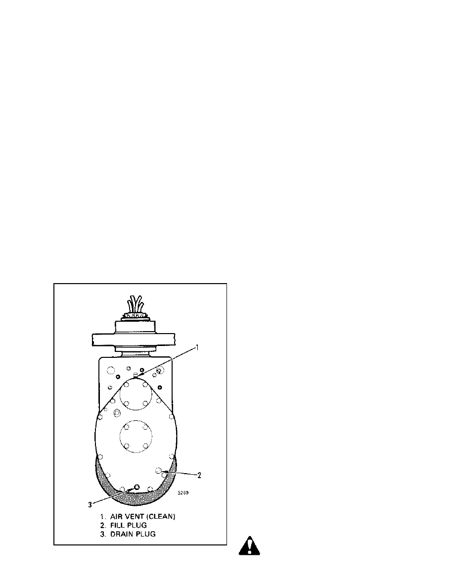
MASTER DRIVE UNIT (Item 2)
(See Figure 2)
Check the level of the lubricant weekly. Fill to
the bottom of the filler neck. Replace lubricant
every 2000 hours or yearly. Clean the air vent
yearly.
LIFT CHAINS (Item 4) (Item 18)
A. Lubricate the lift chains as needed or every 350
hours.
B. Check for correct operation of the lift chains
daily. Check that the chains are in good condi-
tion.
Raise the operator’s platform without a
load until the upright is fully extended. The
stop at the top of the inner channel must
not touch the operator platform. Adjust the
chains if the operator platform touches the
stop. Lower the platform completely.
Put a near capacity load on the forks. Raise
the operator platform and look at the chains
to make sure they have equal tension.
Check the chains through the complete
cycle.
If the chains do not have equal tension or
the chain adjustment is not correct, adjust
as needed. See the procedure for adjust-
ing chains in the UPRIGHTS section
(4000 SRM 235).
Check the free-lift chain of the attachment
for chain condition and correct operation.
The swing head must just touch the base
of the free-lift upright in the fully lowered
position. The swing head must NOT touch
the stop in the fully raised position. 1f nec-
essary, adjust the chain anchor for correct
operation. See the RACKLOADER II AT-
TACHMENT section (5000 SRM 239) to
replace the chain.
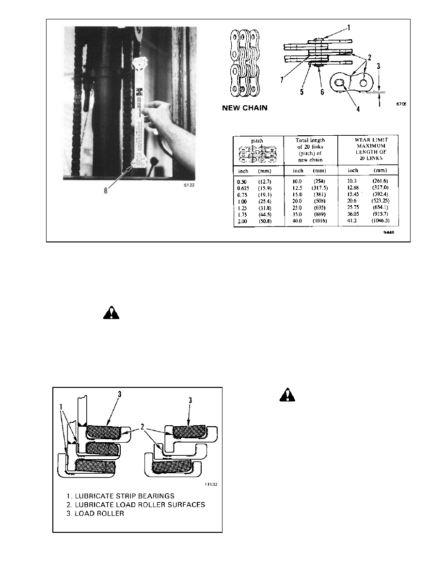
C. Inspect the chains for damage. Install new
chains if they are worn or damaged. See Figure 3.
CAUTION
Never replace just the worn section of a
chain. Replace the complete chain.
Never replace just one chain of a chain
pair. Replace both chains.
FIGURE 2. MASTER DRIVE UNIT PLUGS
AND AIR VENT
1.
2.
3.
4.
UPRIGHT SURFACES (Item 3)
(See Figure 4)
WARNING
NEVER work under a raised carriage
or forks. Lower the carriage or use
blocks and chains on the upright
weldments and carriage so that they
cannot move. Make sure the moving
parts are attached to a non-moving part.
Lubricate the sliding surfaces along the full length
of the channels. Apply a thin layer of multipur-
pose grease to the surfaces in the channels where
the load rollers travel. Apply the grease to both
the roller surfaces and the thrust surfaces in the
channels.
NOTE: The load rollers and sheaves have sealed
bearings and do not need additional lubrication.
FORKS (Item 26) (See Figure 5)
WARNING
NEVER work under a raised carriage
or forks. Lower the carriage or use
blocks and chains on the upright
weldments and carriage so that they
cannot move. Make sure the moving
parts are attached to a non-moving part.
Do not try to correct fork tip alignment
by bending the forks or adding shims.
Replace damaged forks.
Never repair damaged forks by heating
or welding. Forks are made of special
steel using special procedures. Replace
damaged forks.
FIGURE 3. CHECKING THE LIFT CHAINS
FIGURE 4. UPRIGHT LUBRICATION
•
•
•
1. WORN PIN
2. CRACKS
3. EDGE WEAR
4. HOLE WEAR
5. LOOSE LEAVES
6. DAMAGED PIN
7. RUST
8. CHAIN WEAR SCALE
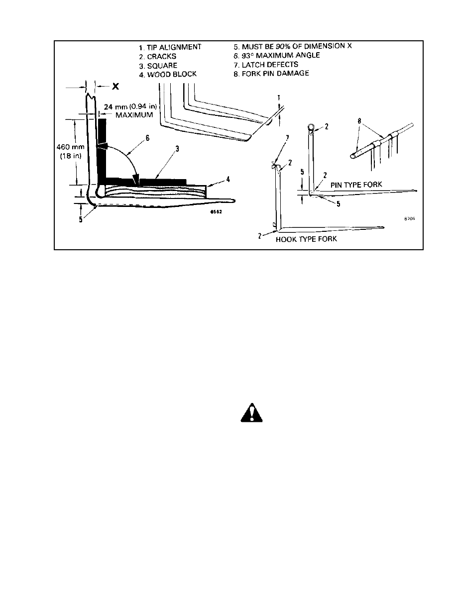
FIGURE 5. CHECKING THE FORKS
EVERY 8 HOURS OR DAILY
A. Check that the fork tips are aligned within 13
mm (0.5 in) of each other. See item 1 of Figure 5.
B. Referring to Figure 5, check forks for cracks.
C. Replace any damaged or broken parts that are
used to keep the forks locked in position.
EVERY 2000 HOURS OR YEARLY
A. Check the heel and attachment points of the
forks for cracks with a dye penetrant process, such
as Zyglo Penetrant, Type ZL22 and Zyglo Devel-
oper, Type ZP9. These are manufactured by
Magnaflux Corporation, Chicago, Illinois 60656.
Follow manufacturer’s instructions for use. Re-
place the forks if any cracks appear.
Use of truck in severe application or suspect of
damage to forks means forks should be checked
more frequently.
B. Measure the thickness at a vertical section of
the forks where there is no wear (Dimension “X”).
Then measure the thickness at the heel of the fork.
If the thickness is not more than 90% of Dimen-
sion “X”, replace the fork.
C. Check the maximum angle (Ref. 6) at the load
center of the fork. If the measured angle is greater
than the specified maximum, replace the forks.
ATTACHMENT ROLLERS (Item 5)
CAUTION
If the side rollers have worn grooves in
the upright beam, shims must be added
for the correct clearance and alignment.
There are lubrication fittings on the four side roll-
ers of the attachment head. The head must be re-
moved from the upright for access to the fittings.
See the RACKLOADER II ATTACHMENT sec-
tion (5000 SRM 239) for removal of the head.
There are small center rollers at the bottom of the
base frame. These shafts and rollers also need lu-
brication. The traverse frame must be removed.
Remove the shaft, clean the roller and shaft and
apply the lubricant.
STEERING SPEED REDUCER
(Item 6)
The speed reducer must be removed to change the
grease. See the ELECTRIC POWER STEERING
section (1600 SRM 220) for the removal proce-
dure.
SPINDLE BEARINGS OF THE
MASTER DRIVE UNIT (Item 7)
The spindle of the Master Drive Unit will be lu-
bricated every 2000 hours or once each year. It is
necessary to remove the Master Drive Unit from
the lift truck. See the procedure described in the
MASTER DRIVE UNIT section (630 SRM 53).
STEERING AND TRAVERSE CHAINS
(Items 8, 0, 19 and 20 )
Use a cloth to clean the chains. Apply a thin coat-
ing of lubricant to all of the rollers of the chains.
Too much lubricant will hold dirt and increase
wear. Check that the chains are correctly adjusted.
See the STEERING and ATTACHMENT sections
of the service manual for the correct procedures.
ELECTRIC CABLE AND HOSE
SHEAVES (Item 10)
The shafts and roller bores of the cable and hose
sheaves need to be cleaned and lubricated every
2000 hours or once each year. Remove the sheave,
clean the shaft and bore and apply the lubricant.
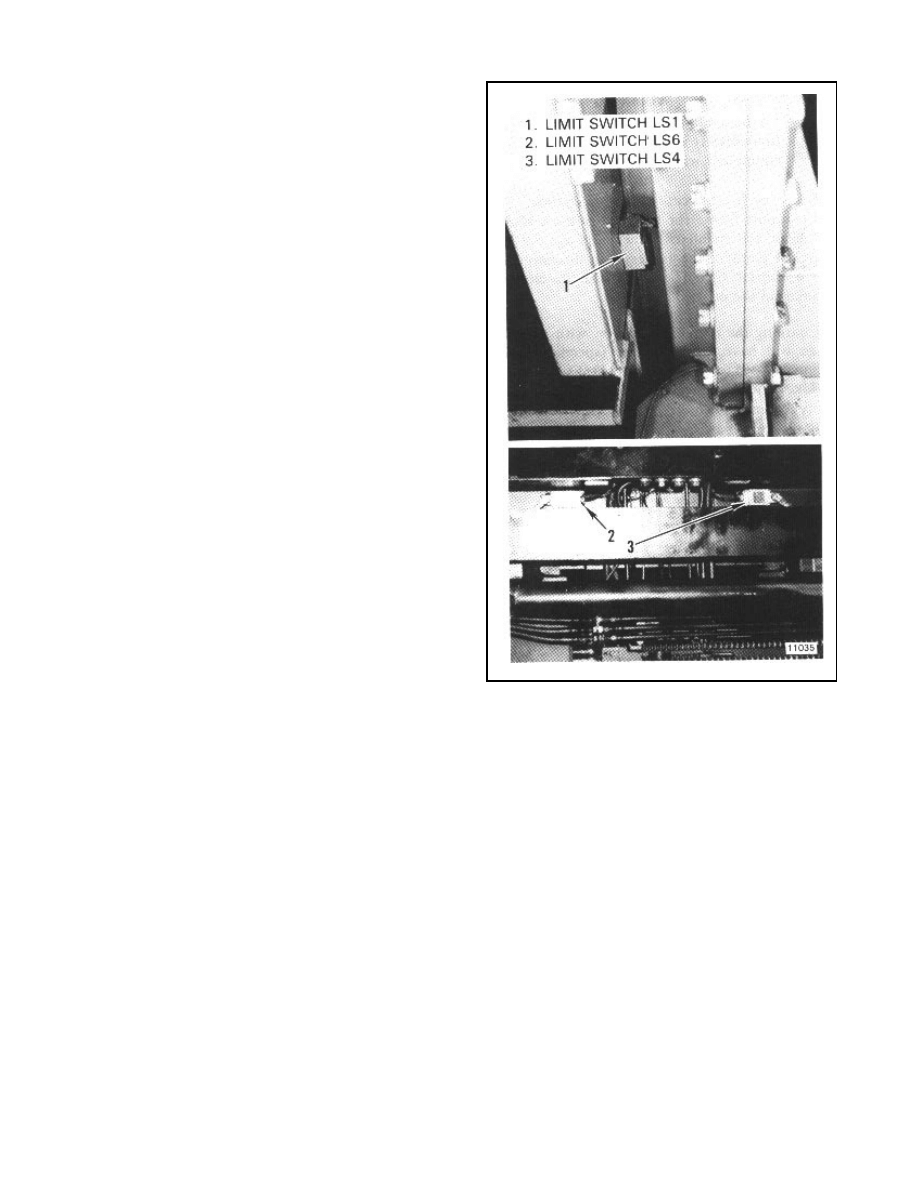
ROLLER SHAFTS OF THE LIMIT
SWITCHES (Item 11) (See Figure 6)
Lubricate the roller shafts of the limit switches
every 2000 hours or once each year. See Figure 6.
Some units that have high uprights also have an
additional limit switch on the upright.
BATTERY (Item 17)
(Figures 7, 8 and 9)
A. Check the battery and cables for damage and
loose connections.
B. Make sure the battery is clean and there is no
corrosion on the connections.
C. Check the electrolyte level DAILY ON AT
LEAST ONE CELL. To prevent battery damage,
check the electrolyte level weekly on all cells. Add
distilled water only. Do not add electrolyte. Keep
the plates covered and do not add too much dis-
tilled water. See Figure 7. Carefully remove any
electrolyte or water from the top of the battery, on
the case or on the floor.
FIGURE 6. LUBRICATION OF THE LIMIT
SWITCH ROLLERS
If the lift truck has been operated with
a battery that has a low charge, check
all contactors for welded contacts before
connecting a charged battery.
Do not put tools or any metal on the
battery.
CAUTION
Make sure the battery charger gives the
correct voltage. The battery charger
must be connected to the battery with
the correct polarity. All of the cells do
not charge equally at a fast rate. The
battery must be charged at a slow rate
monthly. This slow rate is for three
hours after the normal charge rate. This
slow rate of charge is to give each cell
an equal charge.
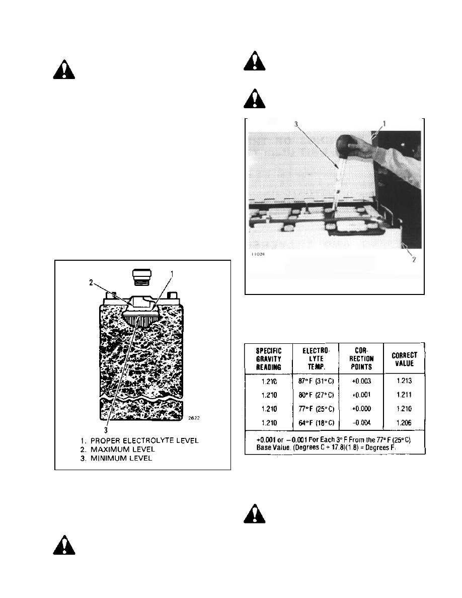
TABLE 1. SPECIFIC GRAVITY
CORRECTIONS
WARNING
Charge batteries only in areas made for
charging batteries. Make sure there is
ventilation. Batteries generate flam-
mable gas when they are being charged.
Keep vents in the caps open. Keep fire
and sparks away from the area.
FIGURE 7. CORRECT ELECTROLYTE
LEVEL
WARNING
The acid in the electrolyte will cause
injury. Immediately wash electrolyte
from body or equipment with water.
D. Keep the battery case clean and painted. The
truck support frame for the battery must also be
kept clean and painted. If the parts are not kept
clean and painted, the battery can discharge and
have a shorter life. There can also be electrical
problems in the control circuits.
E. Charging the battery: A battery with a normal
charge will have a hydrometer (specific gravity)
reading of 1.265 to 1.285 at 25° C (77° F). See
Figure 8. Make a temperature correction for the
specific gravity reading shown on the hydrometer.
See Table 1. Charge a new battery at a slow rate
for three to six hours before putting it in opera-
tion. A battery will be damaged permanently if it
is kept in a discharged condition.
FIGURE 8. CHECKING SPECIFIC GRAVITY
1. BATTERY COVER
2. BATTERY
3. HYDROMETER
CAUTION
Make sure the battery charger is con-
nected only to the battery. If the bat-
tery charger voltage is connected to the
lift truck circuit, the EV-1 control can
be damaged.
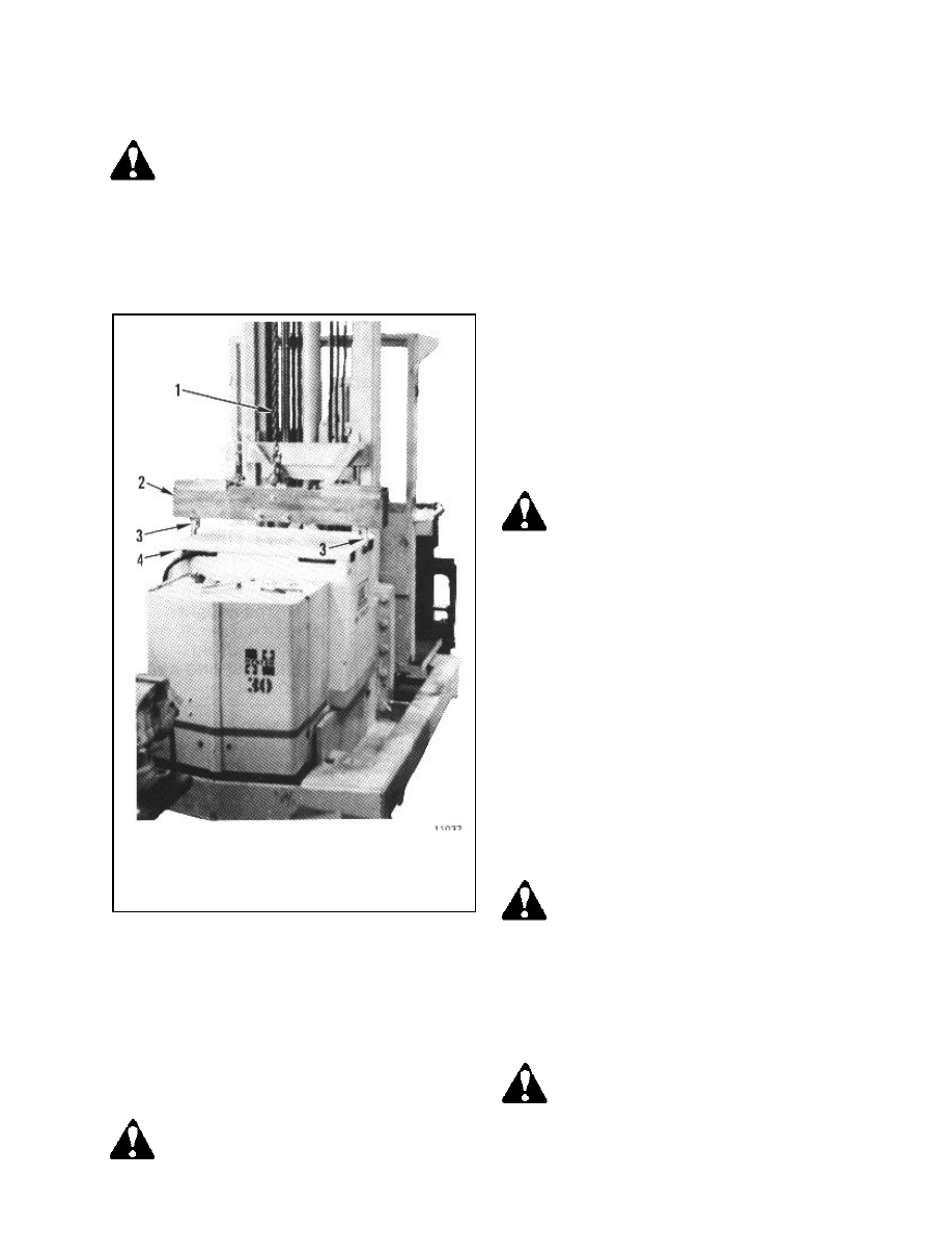
CHANGING THE BATTERY
(See Figure 9)
battery weight is shown on the lift truck
nameplate. If the spreader bar is made
of metal, it must have an electrical in-
sulating material between the spreader
bar frame and the battery.
A battery is heavy. To prevent injury, use care
when moving batteries. The replacement battery
must fit the battery area correctly. Move the bat-
tery as far away from the upright as possible. Use
spacers to make sure the battery cannot move more
than 13 mm (0.5 in) in any direction.
CONTACTORS (Item 20)
WARNING
Always disconnect the battery to pre-
vent injury or damage.
The contact surfaces are made of silver alloy over
a copper base. In normal operation, the contact
surfaces become a dark color and rough. Clean-
ing is not necessary. Do not clean the contact sur-
faces with a file or emery cloth. Replace the con-
tact surfaces when the silver alloy wears through
to the copper base. Always replace the contact
surfaces in sets. Check for equal spring tension if
the contactors do not wear evenly. See the EV-1
section (2200 SRM 155) for correct installation
and adjustment.
WARNING
Operating a lift truck with a battery that
has a low charge can weld the contactor
contacts together. If this happens, the
lift truck can move without control
when a charged battery is connected.
Check the contactors for welded con-
tacts.
CAUTION
Low battery voltage increases contactor
contact arcs and burning of the contact
surfaces. Low battery voltage can cause
damage to motors because of high cur-
rent. Do not operate the truck with a
low battery voltage.
Disconnect the battery. Put a cover on the battery
that is an electrical insulator. Covers are not nec-
essary on batteries that have a cover as part of the
battery case. Use a crane and spreader bar to lift
the battery.
WARNING
Make sure the crane and spreader bar
have a lifting capacity that is greater
than the battery weight. The maximum
FIGURE 9. CHANGING THE BATTERY
1. CHAIN OF CRANE
2. WOOD SPREADER BAR
3. HOOKS
4. BATTERY
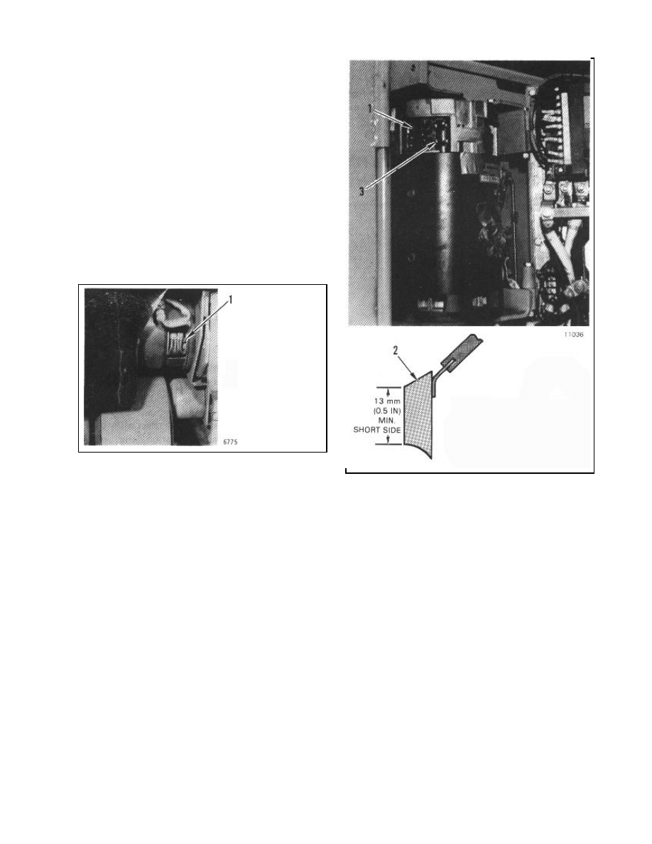
CHECKING MOTOR BRUSHES
(ITEMS 22, 23 AND 24)
Access to the motor brushes is by removing the
inspection cover on each motor. See Figures 10
and 11. Replace brushes that have less than 13
mm (1/2 inch) of brush length on the shortest side.
Check for free brush movement within the brush
retainer. Check for burned insulation, burned paint,
dark colored brush springs, or black commutator.
Burned parts indicate repairs are needed. See the
DC MOTOR section (620 SRM 53) for brush re-
placement and repairing the motors.
FIGURE 10. CHECKING MOTOR BRUSHES
FOR THE MASTER DRIVE UNIT
FIGURE 11. CHECKING MOTOR BRUSHES
FOR THE HYDRAUIC PUMPS
BRAKE SYSTEM (ITEM 25)
Check brake linings for wear. Replace brake shoes
with defects. Adjust brakes as required. See the
BRAKES section for adjustment and repairs. Re-
place the brake shoes if the lining is worn to within
0.8 mm (0.03 or 1/32 in).
1. MOTOR BRUSH
(TYPICAL OF 8)
1. MOTOR BRUSHES
2. BRUSH (TYPICAL OF 8,
EACH MOTOR)
3. BRUSH SPRING AND
HOLDER
Document Outline
- INTRODUCTION
- MAINTENANCE PROCEDURES
- Hydraulic Oil and Filter
- Master Drive Unit
- Lifting Chains
- Upright Surfaces
- Forks
- Attachment Rollers
- Steering Speed Reducer
- Spindal Bearings of the Master Drive Unit
- Steering and Traverse Chains
- Electric Cable and Hose Sheaves
- Roller Shafts of the Limit Switches
- Battery
- Changing the Battery
- Contactors
- Checking Motor Brushes
- Brake System
Wyszukiwarka
Podobne podstrony:
8000237
8000231
8000238
więcej podobnych podstron