THE FREE ENERGY CIRCUIT
By Geoff Egel
This article appeared in Australian Magazine Hard Evidence May/June 2002
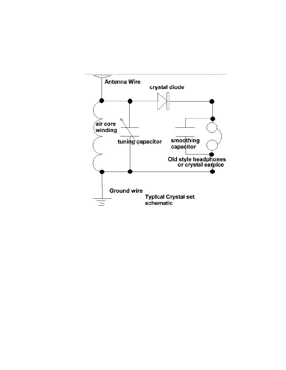
Many will recognize the above circuit as a schematic for the early crystal radio set
receivers that many radio enthusiasts built when young ,I built many in the early
nineteen sixties not only to receive the local AM radio stations but with a suitable
antenna and by changing the coil windings ,size and diameter I was able to receive
Radio Australia and the then ship to shore radio telephone service from Sydney
Australia and, I believe this was over a thousand kilometers away from where I
lived at the time.
Remember the crystal set was able to let your listen to local radio stations without
need for a power supply but run from the power sent out by the radio station itself.
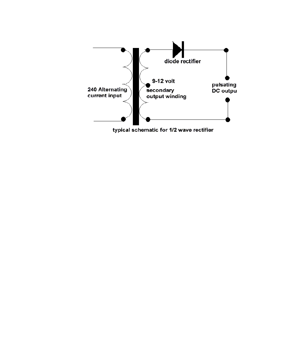
Others with a little imagination can see it as a half wave dc power rectification
schematic .
This is an interesting circuit and as is the case in nature where nature uses
common designs for each of its various creation, so it may be the case that the
circuit designs as shown above may be the common circuit that may be useful in
uncovering the secrets to free energy.
After seeing the simple circuit as described by Dr Peter Lindemann Dsc I was
stuck by the similarity between the circuits that other free energy researchers
claimed to have used in their invention.
The basic concept as I understand it, is a high frequency high voltage, low current
rectified and then used to charge a bank of high value and high voltage capacitors
and then to discharge them in pulse mode for brief period of time, nano seconds in
fact by, means of a high speed electronic switching circuit or mechanical device
and a rectification method that will only allow the high voltage charge to flow in
only one direction .
The switching device of firing device could be a rotating spark gap as used by
Nicola Tesla or some high speed electronic device, it is my belief that only glass
tubes such as diodes or triode valves are really good at this and not transistors as
they cannot handle the high voltage and high current produced in these devices
without burning themselves out..

This type of design can produce a very high amperage current for a faction a
second that can used to do some useful work if properly harnessed.
A point to remember is that Paul Baumann claims to have built his first device
called the Testakica when in prison and as such did not have access to exotic
materials as is often described in other theories of how the Testakica free energy
machine was said to have worked.
Please note engineers from Europe have actually seen the device working.
One would conclude from this, that as such, that the home experimenter should
also be able to build such a device from material source from around the home and
the local area.
REMEMBER THE KISS PRINCIPLE AND KEEP IT SIMPLE STUPID.
Getting the high voltage to start with.
There are two main types of methods that I am aware of are they are.
STEP UP VOLTAGE transformer

As used by Edwin Gray in his invention the charging circuit is basically a 12 volt
battery being driven by vibrating relays to pulse the power through a step up
transformer to raise voltage from 12 volt to approx 3000 volts this then, is rectified
and used to charge a bank of high voltage capacitors.
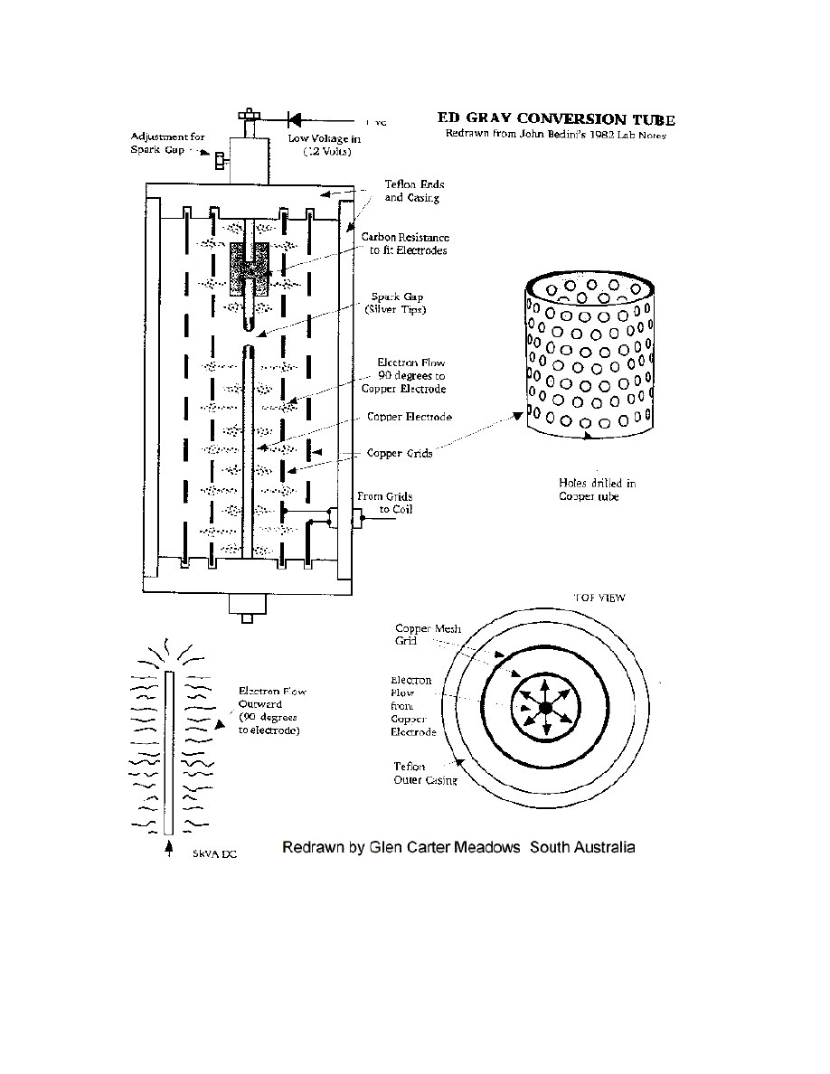
This bank of capacitors is then discharged for a nano seconds period into special
design tube which seems nothing than a copper rod a spark gap some carbon with
maybe enclosed oxygen and a series of concentric rings around the spark gap and
the resulting power collected on those rings is then fed to the earth via a air
induction transformer or to the positive terminal of the charging batteries .

The power appearing at secondary of this air induction transformer is then used to
power the motoring coils of the specially design motor.
High Voltage Induction Coil
Another method used in early X-ray machine and also Marconi in his first radio
transmission across the Atlantic ocean was the induction coil basically a two coils
wound on a metal rod a small number of primary windings in heavier gauge wire
and large number of finer gauge winding ,basically a step up transformer using the
primary magnetic field to operate a switch that controls the power to the primary
winding.
This causes the magnetic field in the primary coil to build up and down which then
causes an induction an alternating high voltage output in the secondary coil.(most
likely a square wave)
A home made Wimshurst Machine
Electrostatic generation of high Potential.
The People at the Swiss Community of Merithnita seem to be using a Wimshurst
machine to generate the high voltage needed to run their free energy device and
home workshop handyman should be able to construct one for themselves
Check the following website for more details on this device
http://energy21.org/swiss.htm
The device was a popular means to generate high voltage in the late 19 century and
early 20 century .
It role was at some stage used to provide the high voltage needed for early x-ray
machines in hospitals but today is usually superceded by the modern electronic
version or the Van de Graaf machine in modern physics laboratories today.
The Wimshurst design is basically two counter rotating disks of a plastic or glass

material upon which are place metal foil leaf sections spaced and separated from
each other around the disk surface..
These twin’s discs are spun in opposing directions on a common axle by means of
a belt either hand driven or motor driven.
Brushes mounted at various points near the disk’s metal plates but not touching the
disk collect the charge and usually then conduct it to a capacitor storage position or
discharge the built up charge through a spark gap.
ANOTHER DEVICE IS CALLED A DIROD invented by A.D.MOORE
This a flat circular plastic disk upon which have been glued several conductive
metal rod’s mounted in radial positions around the disk.
This disk is spun by means of a hand crank
Four pickup positions mounted along side the spinning rods pick up the charge
through conductive foil or conductive plastic as used in computer electronic parts
packaging and then either discharge the high voltage buildup through a spark gap
or charge a capacitor bank.
It is my conclusion that the Single Swiss disk version of the Testatika makes use of
the Dirod principle in it’s design of the smaller version of the single disk Testatika
machine to generate the high voltage potential.
I refer to the circuit diagram as reproduced below which consists of transformer
which raises the voltage to several thousand volts which charges a capacitor bank
to several thousand volts and then discharges it across a spark gap.
In the original patent drawing as produced by Stan Meyers the transformer appears
to be an automotive step up transformer but as friend has indicated to me that the
coil would be unable to handle the frequencies needed to make this circuit perform
,he however has removed the center core material and has found he is able to use it
at high frequencies.
My friend is using a waveform generator (square wave ) to drive an electronic high
voltage car ignition system as used in modern automobiles ,I think he had made it
from kit.
I saw him using this setup to drive high voltage sparks across some ½ inch carbon
rods and it seemed rather impressive.
He used a car battery as the power source.
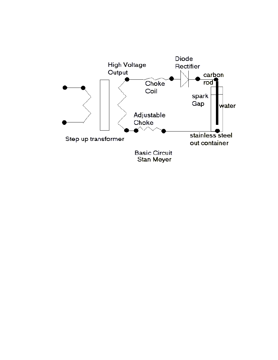
A POSSIBLE STAN MEYERS CIRCUIT
http://www.Fortunecity.com/greenfield/bp/16/stanleymeyer.htm
This circuit appears to charge a water cell with a high voltage source , Stan Meyers
claims he had to resonated the water cell with a high voltage charge and then when
the dielectric would break down, the resulting high current through the water
causes electrolysis and breaks it down into hydrogen and oxygen as well as other
dissolved gases in the water that could then be used to power a motor vehicle on
demand..
The question of him resonating the cell as indicated in his patent application would
appear to be incorrect as he has added a diode in the output circuit this would in
fact making it a high voltage DC pulsating circuit, this could also be the method
that xogen.com were using to get their big advances in hydrogen production.
This circuit diagram would now appear to be a simple high voltage charging circuit
and the water cell is now in fact acting like capacitor and the dielectric being the
water itself.
The choke coils in the circuit and one seems to be adjustable maybe to prevent the
premature voltage breakdowns due to short high voltage spikes that would need to
be avoided.

Other’s more in the know of the function of such circuit could perhaps fill me and
others in more,
As I understand it when the voltage reaches a point where the dielectric
breakdowns ,the voltage short circuits causing a high current surge for a brief
period time causing the water to break down into gas combinations by means of
electrolysis releasing both hydrogen ,oxygen and the other dissolved gas in the
water..
A friend of mine has used carbon rods in some high voltage experiments and has
found that they seem to work better than stainless steel ones which seem to
contaminate the water cell, he has found that by using carbon welding rods the
contaminating action does not seem to occur.
He has also tried the circuit with out the rectifying diode and found that he could
get any gas to form.
He has limited success using two carbon rods in the container at this stage..
I feel however that if you use a single carbon rod in the center of metal water
containment vessel and use it also as the other terminal it might be possible to get
greater output of gases.
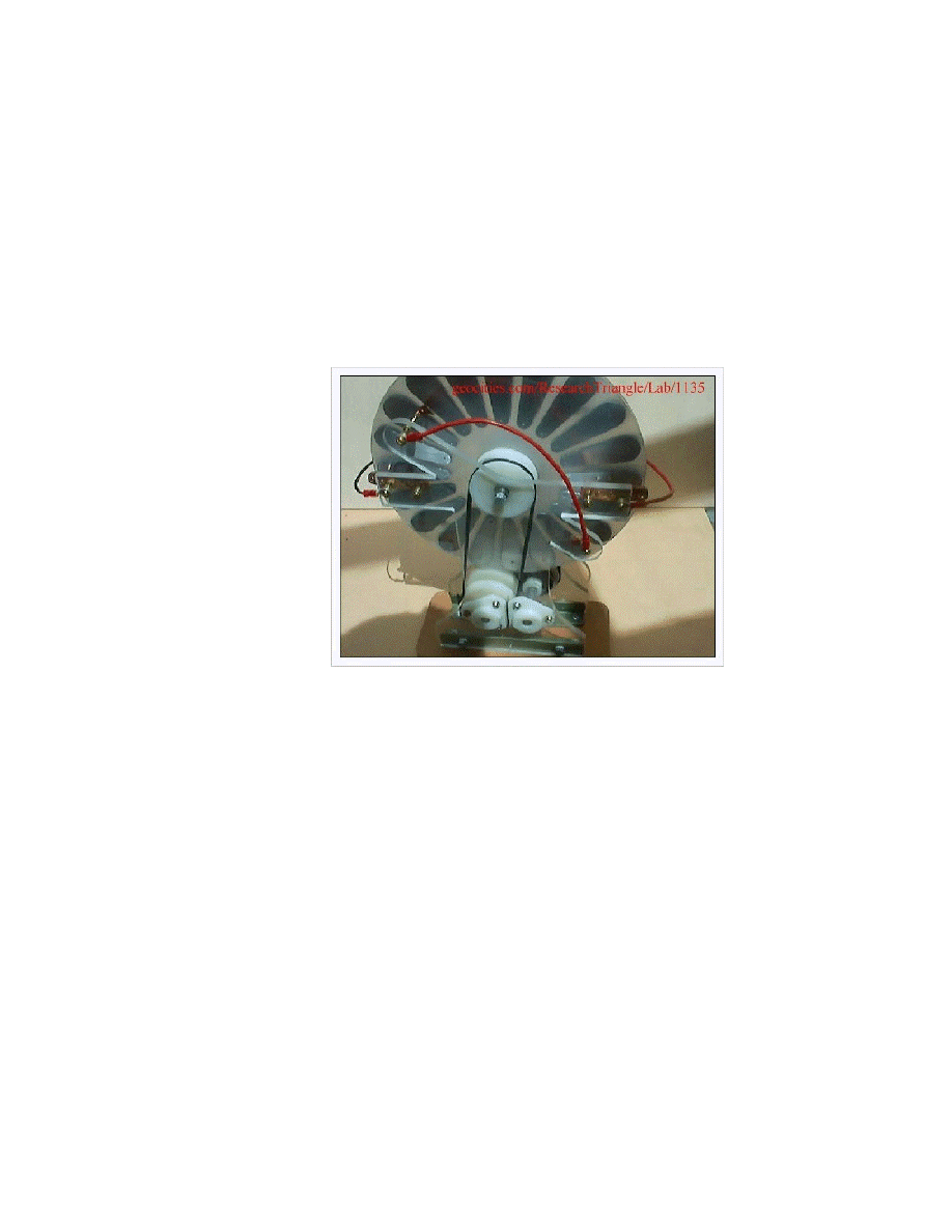
THE POWER WHEEL OF CALVIN BAHLMANN
Calvin has built a power wheel using NIB magnets and special coils.
The large plexi glass wheel is covered with neo-boron magnets which revolve at a
constant rpm ,the coils only gather a voltage but this is used to charge a capacitor
bank which discharges at predetermined ratio to the driving coils.
It’s certainly impressive to see his large unit running on a small nine volt battery
and not missing a beat.
One could assume that the nine volt battery did not have power enough to drive
this thing.
The device was on show recently at Bruce Perrault inventors 2001 weekend and I
would certainly recommend you get yourself a copy of the video.
http://nuenergy.org
JOHN BEDINI
John Bedini has been doing something with similar with coils and capacitor banks

using trigger swiches mounted on additional rotating smaller wheel to run his
machines.
This apparently he has done for years but largely ignored ,but has had some
success lately with a student winning a science fair award with a variation of his
idea and the granting of a U.S. patent.
http://www.Fortunecity.com/greenfield/bp/16/student.htm
The device is basically a roller to which four magnet have been attached and
moving over a magnet pickup coil and a drive coil on the same former.
The device is not self starting but once spun as I understand it will continue to run
with the magnetic field produced in the pickup coil by the spinning magnets
switching the drive circuit transistor and acting as switch to pulse the current need
to fire the motive coil.
I have tried to reproduce the device myself ,but with little success ,but have no
doubts that John Bedini ideas works and the trouble is at my end not his.
John Bedini has been granted a patent on a more complex device based on this
principle and hopefully something positive comes of this.
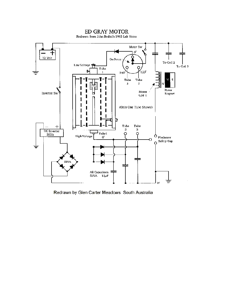
Ed Gray Circuit
This too seems to a circuit with similarities with the others
Here a bank of batteries is used to create a high voltage and is transformed by
means of an air core transformer then rectified and then used to charge a bank of
capacitors
The capacitors then are in turn discharged through spark gap and for a brief period
of time by some means mechanical or other means and into a special tube and
spark gap rod component that appears to consist of some carbon and other metals
surrounded by a grid that some say collects the high charge resulting in the buildup
of voltage in the spark gap conductors prior the discharge from the area
surrounding the spark gap.
This then claimed excess energy is collected from the surrounding cylinders and
then transformed to do useful work.
The Testakica Machine
I have had an interest in these machine for some time ,but never really understood
how it worked but knew it had to be based on something simple as the Inventor

Paul Buamann built his first unit in prison and would have not been able resource
exotic materials as have claimed by to be the method by which the device works.
It would seem to me be based around some of the concepts as discovered Edwin
Gray.
The spinning wimshurst machine twin disc’s creates the high voltage source need
to charge the capacitor bank which are then discharged at a precise time period ,I
believe the rectification mentioned in video refers the stopping a reverse current
and voltage flow as is the case in Edwin Gray Device
This is how I think the Large machine works although no one apart from
Merintnita organization really know and with the death of Paul Bahmann the secret
may be lost forever.
I believe the machine actually collect and stores high voltage collected from the
spinning disk.
The video says the device is started by spinning the disk by hand. And then
becomes self running.
The video also says the device need to operate a given speed and apparently slowly
as well.
The device rectifies the high voltage produced.
There appears to be more pickup points than is really needed to capture the high
voltage ( a wimshurst machine really only needs only eight collecting positions on
the disk to function , and
I suspect the other eight brush positions are a method to feed some of the high
voltage produced from the cans area on the device to enable it to be used as a
propelling force which is possible if the disc’s are properly balanced,
See more of high voltage motoring rotating cups here’
http:// www.Fortunecity.com/greenfield/bp/16//ionmotor.htm
What it does not say that there must be a firing control for the high voltage,
possibility a version of a rotating spark gap, I suspect this is controlled by means
somewhere on the disk either directly or by means of the belt drive that appears to
be on the machine as a speed control function.
Theres a Pal video that’s out there that was produced approximately 20 years ago
now that gives a detailed account of the metherinthina community and show the

testakica machine working.
John Bedini on his machine uses a separate disk driven with belt to main revolving
wheel with a contact point on it to fire the pulse for his machine maybe it
something similar for the Testakica.
I notice on The Testakica machine video what appears to be a relay or pickup coil
opposite a revolving wheel which needs some explaning as to what it function
could perform.
I agree with others that now say the big cans perform a function similar to the Ed
Gray Capture tube but I think with a slight difference.
I believe there could be a rotating spark gap controlling the high voltage pulse
delivered to the tube and that there is no spark gap as such in the capture tube but it
could have a large carbon rod in each and then connected in series to the other rod
in the other capture tube as well as the rotating spark gap and the high voltage
capacitors.
I noticed too that Ed Gray used a piece of carbon in his device and called it a
carbon resistor, I have my doubts as to the value of the resistance value.
I am not sure but I believe the carbon mentioned here is a form of graphite as used
in normal lead pencils and some small voltage dry cell batteries and in some
welding applications.
I have noticed too that several other experimenter using carbon components in
their type of devices and are getting better results than expected as well.
I have been informed that graphite brick’s were also used in the first atomic pile.
Apparently some capacitor manufactures today are using carbon plate’s area’s to
manufacture superior capacitors so carbon itself could be something to examine
closely.
Telsa is also said that carbon was excellent at capturing the energy he was
experimenting with, so I would suggest that there is a whole carbon rod running
the entire inside length of the large capture cans shown in front of the testakica in
most photographs I have seen of the device.
DONALD L SMITH
It has come to attention that an elderly inventor in the United has build a Tesla coil
and then surrounded it with a collection of other coils that resonate in time with the

main coil arrangement.
With this the inventor claims to be able to manipulate the surrounding electrical
fields in the Tesla coil so that it is reproduced in each other coil surrounding the
main Tesla coil ,it seems each coil itself collects and reproduce the power sent
from the main coil.
This the inventor seems to allows collection of power that could be in excess of
over unity but the inventor makes no claims as to such a fact that this is indeed the
case
.This example is not practical but if you had hundreds of exactly tuned crystal sets
to the same frequency around a powerful transmitter, would each new receiving set
reduced the overall signal strength available to the other sets.
I think not.
So Donald L Smith could be on to something.
Another example is the resonating glass trick ,this is done by moving a finger
across the top of thin walled glass and if this is done correctly it will cause the
glass to produce a ringing sound.
If there are glasses exactly the same nearby they too will resonate as well.
Interesting subject the power of resonance.
THE PEOPLE MOVER
Some months ago now there appear on TV from the United States a motor scooter
that was said to be the IT or Ginger that people have appeared curious about for
some time.
I have heard it can run at 12mph for 24hrs on a few cents of electricity, I not aware
of any batteries that can provided this much power for this amount time ,So could
this be the first of free energy devices on the market and the inventor seems to
indicate that there more come.
For more detailed information and related energy material on this subject of free
energy and other related articles with a wide range of schematics ,diagrams and
drawings that we cannot provide here please visit our energy21 website which by
the way some claim on the web as the best free energy website and it’s Australian
as well

at http://www.Fortunecity.com/greenfield/bp/16/
Other resources to visit on the internet are
http://
www.Fortunecity.com/greenfield/bp/16/
content1.htm
The energy 2000 newsgroup
http://groups.yahoo.com/group/group/energy2000
Other resource recommended energy sites.
Astro
Alternative Science and Technology Research Alternative (Adelaide South Australia )
http://astrosa.8k.com/
Clear Tech Peter Lindemann own website
http://www.free-energy.cc/
From JlN Labs France
http://jnaudin.free-fr/
About the Author.
Geoff Egel is web page coordinator who has created the energy 21 web site and others.
He has had an interested in the free energy scene for the past twenty years and is a backyard
experimenter and maintains contract with others in the field.
He also maintains the energy 2000 newsgroup and has also completed a massive 600 meg CD
called the encyclopedia of free energy.
Check at
http://angelfire.com/ak/egel/ver2.html
for more details
Although with no formal qualification he has built up a comprehensive collection of articles on
the web from many other researchers in the fields.
He can be contacted directly by email at
egel@main.murray.net.au
or via the energy2000 newsgroup.
Wyszukiwarka
Podobne podstrony:
Free Energy Projects 2
Free Energy & Technological Survival Homemade Wireless Antenna
Magnetic Energy Free Energy
Kto,blokuje tą wiedzę Antenna To Replace?tteries And Provide Unlimited Free Energy For Electric?rs
Free Energy Bedini Device And Method For Pulse Charging A Battery Patent Info 2004
free energy pl
Free Energy Projects 1
Final Secret of Free Energy Bearden
Bedini Radiant Battery Charger (Free Energy)
Nowoczesne technologie - energia za darmo, Free Energy Różne materiały
Zjawisko kawitacji, Free Energy, Dokumenty(1)
Jak napędzać samochód energią punktu zerowego, Free Energy
Darmowa energia- silniki, Free Energy
Free Energy Eolica (Muy Bueno)
Pasywne rezonatory pól torsyjnych, Free Energy
20 Years Bearden Bedini Free Energy Generation Solid State Battery Charger
Free Energy Projects 2
Free Energy & Technological Survival Homemade Wireless Antenna
więcej podobnych podstron