Plans
N O W
page 1
© 1998, August Home Publishing Co.
Blanket Chest
MAGAZINE
W
oodsmith
from
Have you ever noticed how dovetails are
always hidden away on the corners of a
drawer? It’s never seemed quite right to me
that one of the strongest, and most aes-
thetically pleasing joints used in wood-
working is constantly kept from view.
This hasn’t always been the case. In the
18th and 19th centuries, country furniture
often used dovetail joinery because of its
strength and durability. Rather than spend-
ing a lot of time and effort hiding the join-
ery, craftsmen used the exposed dovetails
as both an integral part of their design, and
as a display of their skill.
This is one reason why country furni-
ture, with its simple, functional design has
always fascinated me. So it was only nat-
ural to use this “country” style when I
decided to incorporate exposed dovetail
joinery in a typically old-fashioned project
- a blanket chest.
Unlike many of the modern hope chests,
with their overabundance of frills, this chest
is modeled after some of the original coun-
try versions. The drawers are a good exam-
ple. Unlike the false fronts that are tacked
on the modern versions, all three drawers
on this chest are functional.
In keeping with the traditional theme, I
decided to build the chest out of cherry ...
a wood that was very abundant, and often
used during this period. Although moths
aren’t the problem today they were at one
time, I added cedar to the bottom of the
main box so that every time I open the lid,
the aromatic scent fills the room.
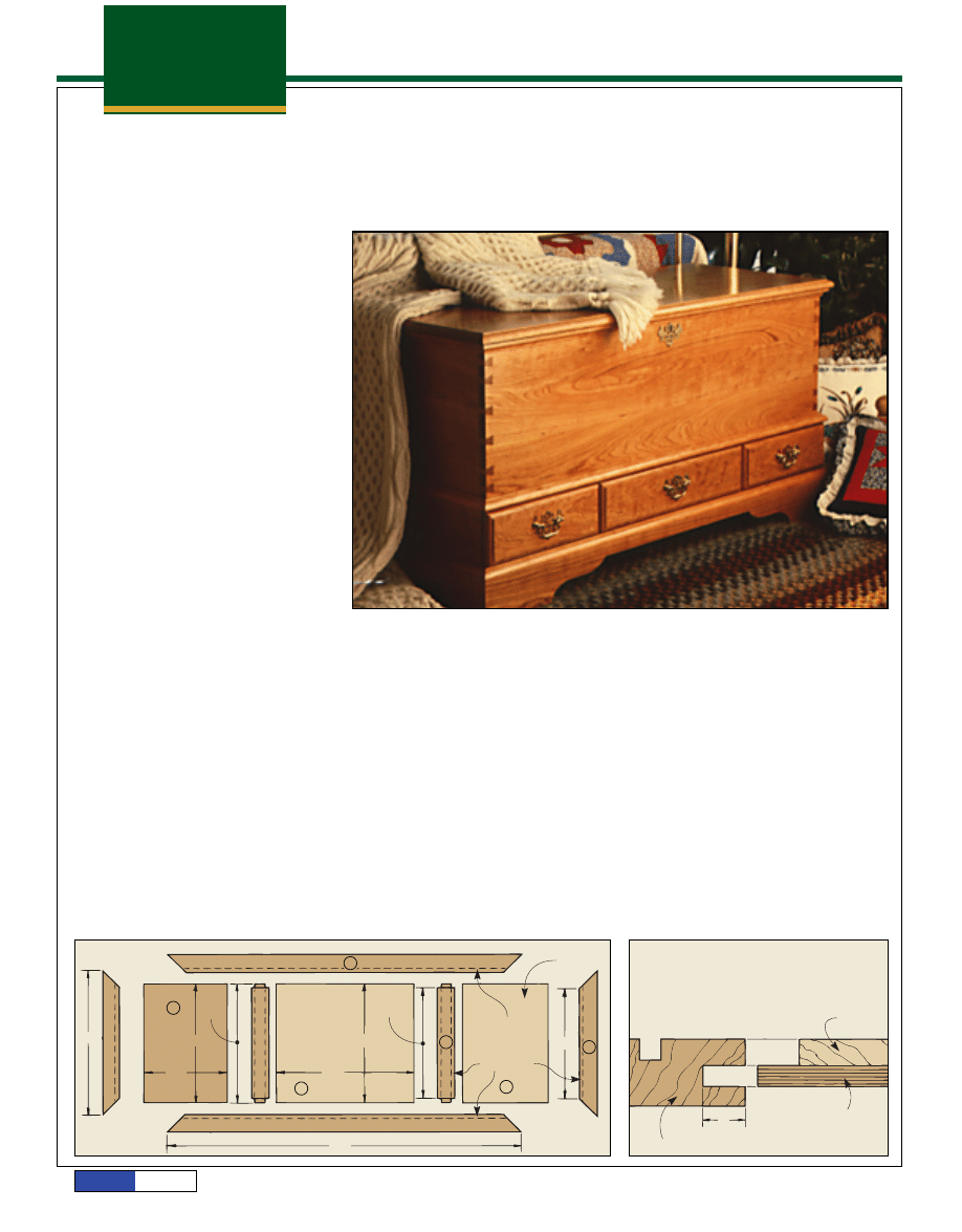
THE FRAMES
The blanket chest consists of three sec-
tions: the main box, the drawer carcase
that houses the drawers, and the kickboard
assembly. I started by building the two
frames that form the drawer carcase.
Both of the frames that form the draw-
er carcase are identical, and use typical
web frame construction that includes
1
/
4
”
Masonite panels, and cedar closet lining
(available at local lumberyards) attached
over the panels.
The first step is to cut the stiles (A and
B) and rails (C) for the upper and lower
frames 1" to 2" longer than their finished
lengths, and to a final width of 2
1
/
4
", see
Fig. 1.
PANEL GROOVES.
Next, grooves are cut
for attaching the Masonite panels on inside
edge of each frame member. Using a piece
of the cedar as a guide, the groove is posi-
tioned so that the cedar will be flush with
the frame members after it’s attached to the
Masonite panels, see Fig. 2. Then a
1
/
4
"-
wide groove (matching the thickness of the
Masonite) is cut
1
/
2
" deep on the inside edges
of the front and back rails (C), the end stiles
(A); and on both edges of the center stiles
(B), see Fig. 3.
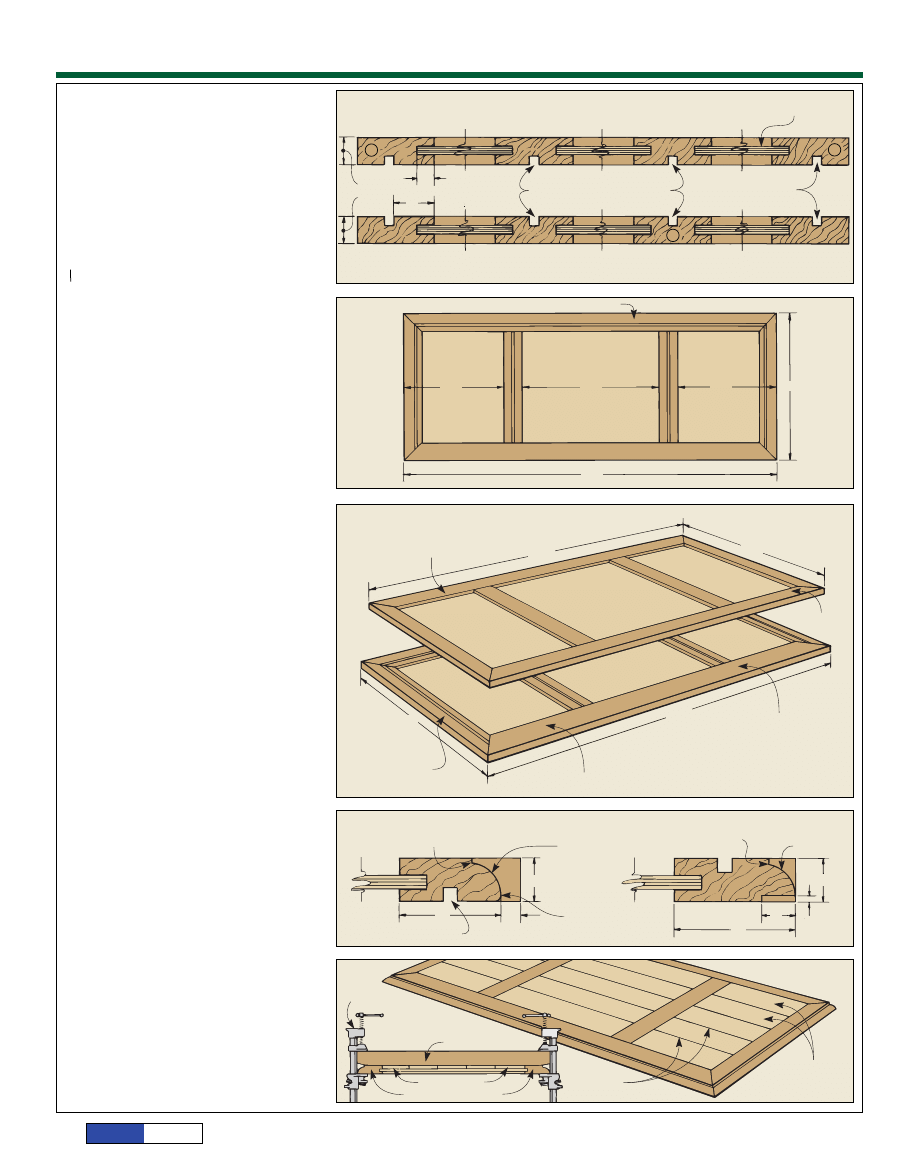
APRON AND DIVIDER GROOVES.
The next
step is to cut grooves for mounting the
aprons and drawer dividers between the
frames, see Fig. 3. For mounting the
aprons, cut a
1
/
4
" x
1
/
4
" groove on one face of
the back rails (C) and end stiles (A),
3
/
4
"
from the inside edge, see Fig. 3. For the
drawer dividers, cut a
1
/
4
" x
1
/
4
" groove on
one face of the center stiles, centered on
their width.
MITERING THE FRAME.
Once the grooves
are cut, the frame members are mitered
to final length. The front and back rails (C)
are mitered 43
1
/
2
" long from point to point,
and the end stiles (A) are mitered to 18
1
/
4
"
lengths, see Fig. 1.
A
U
U
V
B
C
FIGURE 1
18 ”
!/4
14 ”
#/4
14 ”
#/4
14 ”
#/4
10 ”
#/8
WIDTH OF FRAME
MEMBERS 2 ”
!/4
43 ”
!/2
GROOVES CUT
ON BOTH SIDES
OF CENTER
STILES
13 ”
#/4
16 ”
#/4
!/4” MASONITE
PANEL
!/4
!/2
” x
” DEEP
GROOVE
ON ALL
FRAME
MEMBERS
13 ”
#/4
FIGURE 2
CROSS SECTION
LOCATION OF GROOVE
DETERMINED BY
THICKNESS OF CEDAR
CEDAR
!/4” MASONITE
!/2”
FRAME MEMBER
Plans
N O W
page 2
© 1998, August Home Publishing Co.
CUT TENONS.
To join the center stiles (B)
between the front and back rails, stub
tenons are cut on both ends to fit the
grooves in the rails. The final shoulder-to-
shoulder length of the center stiles should
equal the heel-to-heel length of the end-
stiles (13
3
/
4
").
PANELS.
Once the tenons are cut, the end
panels (U) are cut 10
3
/
8
" x 14
3
/
4
", and dry
assembled with the frame to find the
dimensions for the center panel (V). Then
measure the center opening, and cut a
1
/
4
"
Masonite panel to fit the groove-to-groove
dimensions, see Fig. 4.
ASSEMBLY.
After the panels are cut to
size, dry clamp both frames together to
make sure that everything fits and the
assembly is square. Once everything checks
out, glue both frames together ... with the
panels glued in place.
MOLDING
When the frames are dry,
3
/
8
" is trimmed off
all four sides of the upper frame, see Fig.
5. By cutting an equal amount off all four
sides, the grooves for the apron and draw-
er dividers in the upper frame remain per-
fectly aligned with the grooves in the lower
frame. (In this case, the upper frame will
be a total of
3
/
4
" smaller in both dimensions
than the lower frame.)
RABBET THE LOWER FRAME.
Next, a rab-
bet is cut on the bottom edge of the lower
frames so the kickboard can be joined to it.
Note: When cutting this rabbet, be sure
it’s on the face without the
1
/
4
" x
1
/
4
" groove,
see Lower Frame detail in Fig. 6.
ROUT THE EDGE.
The top outside edges on
both frames are routed using a
1
/
2
" corner
round bit, leaving a
1
/
8
" shoulder. Note: On
the upper frame, this molding is cut on the
face without the
1
/
4
" x
1
/
4
" groove, see Fig.
6. On the lower frame, this cut is made on
the face with the groove.
After the corner round was cut on both
frames, I softened the bottom edges of the
upper frame, see Fig. 6. This edge can be
removed with a sander, or with a
1
/
4
" round-
ing over bit set for a very shallow cut.
CEDAR LINING.
Next, the cedar closet lin-
ing is attached over the panels. First, trim
off the tongue and groove moldings on the
edges of the cedar. Then I ripped five equal
width pieces to fit the panel opening, leav-
ing a small gap between each piece for
expansion, and cut the cedar to fit snug
lengthwise in the panel opening.
To glue the cedar to the frames, I used
yellow glue and clamped the slats in place
using clamping boards and pipe clamps,
see Fig. 7.
SAND.
With the cedar glued in place, light-
ly sand both the cedar and the frame. (Note:
Be careful not to oversand the edges of the
frame that mate with the box and drawer
carcase.) Then the frames are joined with
aprons and dividers to form the drawer
carcase.
A
A
B
FIGURE 3
TOP FRAME CROSS SECTION
!/4” MASONITE
!/4
!/4
” WIDE,
” DEEP GROOVES
CENTERED ON CENTER STILES
ALL GROOVES
” WIDE,
” DEEP
!/4
!/4
BOTTOM FRAME CROSS SECTION
!#/16”
!/2”
#/4”
FIGURE 4
BACK RAIL
11 ”
%/8
15 ”
#/4
11 ”
%/8
18 ”
!/4
NO GROOVE ON FRONT RAIL
43 ”
!/2
FIGURE 5
TRIM
” OFF ALL
FOUR SIDES OF
UPPER FRAME ONLY
#/8
42 ”
#/4
17 ”
!/2
END STILES AND RAILS
ARE 1 ” WIDE
ON UPPER FRAME
&/8
!/4” MASONITE
PANEL
UPPER FRAME
18 ”
!/4
43 ”
!/2
NO GROOVE ON FRONT
RAIL ON BOTH FRAMES
STILES AND RAILS
ARE 2 ” WIDE
ON LOWER FRAME
!/4
LOWER FRAME
FIGURE 6
UPPER FRAME
!/8” SHOULDER
!/2” CORNER
ROUND BIT
KNOCK OFF
CORNER
WITH
”
CORNER ROUND
!/4
GROOVE FOR APRON
1 ”
&/8
#/8”
!#/16”
LOWER FRAME
!/8” SHOULDER
!/2” CORNER
ROUND BIT
!#/16”
%/8”
!/8”
2 ”
!/4
FIGURE 7
PIPE CLAMP
UPPER FRAME ONLY
CEDAR SLATS
CEDAR SLATS
CROSS SECTION
CLAMPING BOARD
UPPER FRAME RAILS
!/16” SPACE
BETWEEN
CEDAR SLATS
Plans
N O W
page 3
© 1998, August Home Publishing Co.
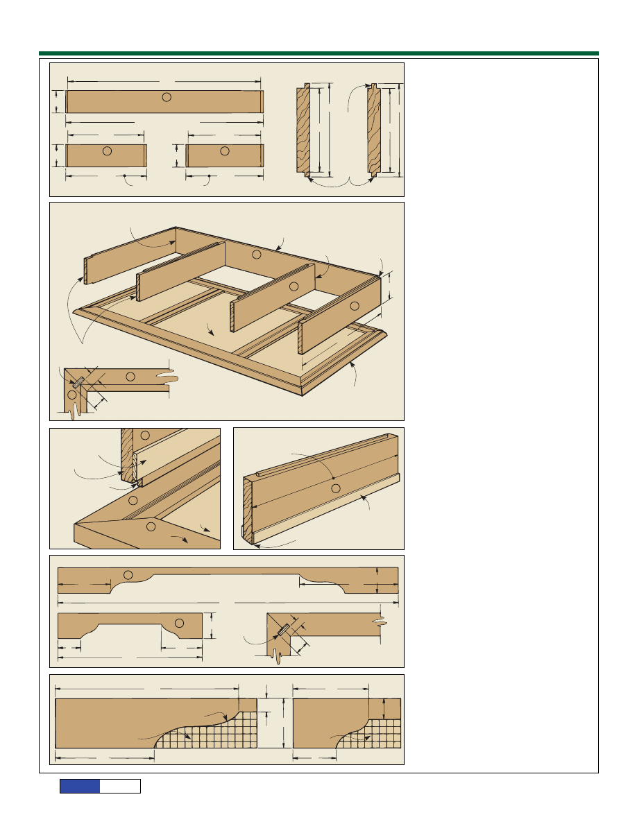
THE DRAWER CARCASE
Aprons and drawer dividers are used to
connect the two web frames, and complete
the drawer carcase assembly, see Fig. 9. I
started by cutting the aprons (D and E),
and the drawer dividers (F) 5" wide, and to
rough lengths, see Fig. 8.
TONGUES.
The next step is to form
tongues on the aprons and dividers that fit
the
1
/
4
"-wide grooves in the frames. On the
drawer dividers (F), rabbets are cut on
both edges to form tongues centered on
the thickness of the divider, see Fig. 8. The
shoulder-to-shoulder width between the
rabbets should be 4
1
/
2
".
On the aprons (D and E), rabbets are cut
so the tongues are flush with the inside
face of the apron. Be sure that the shoul-
der-to-shoulder width is exactly the same
as on the drawer dividers (4
1
/
2
").
MITERS.
The back corners of the aprons
are joined with a mitered spline joint to
help keep everything lined up during
assembly. Miter the back corners of the
side aprons so the tongue is on the heel
side of the miter, see Fig. 9. Then the front
edge on both end aprons is trimmed so the
overall length is 16
1
/
2
". Also, trim back the
tongue on the aprons to fit the grooves in
the frames, see Fig. 10.
Next, I inserted both end aprons (D) in
the upper frame, and mitered the back
apron (E) to fit between them.
MITERED SPLINE.
While the saw is still
set at 45°, cut a
1
/
4
"-deep kerf on the face of
the miters for the
1
/
8
"-thick Masonite
splines, see Detail in Fig. 9.
TRIM DIVIDERS.
Then the drawer dividers
(F) are trimmed to the length of the end
aprons, less the thickness of the back apron
(so the front edges of the dividers and
aprons are flush).
DRAWER GUIDES.
To complete the draw-
er carcase, I cut
1
/
8
" x
3
/
4
" drawer guides,
and glued them to the end aprons and draw-
er dividers as shown in Figs. 10 & 11.
Although all the parts for the drawer car-
case are finished at this point, it’s not
assembled until after the kickboard assem-
bly and the main box are built.
KICKBOARD ASSEMBLY
The kickboard assembly consists of a mold-
ed frame that’s joined with miter and
splines, see Fig. 12.
The kickboard sides are cut 3
1
/
2
" wide
and long enough to fit the rabbet on the
bottom edge of the lower frame, see Fig. 12.
Then the patterns shown in Fig. 13 are
traced on the kickboard sides, cut out using
a band saw, and the kickboard assembly is
glued together.
MAIN BOX
With both the drawer carcase and kick-
board assembly finished, it’s finally time
to cut some dovetails.
E
F
D
FIGURE 8
42 ”
!/8
BACK APRON
5”
5”
5”
5”
5”
ROUGH LENGTH 44”
16 ”
!/2
END APRONS (2)
17 ”
!/4
ROUGH DIMENSIONS
DRAWER DIVIDERS (2)
16 ”
!/4
15
”
!%/16
APRONS
4 ”
!/2
4 ”
!/2
DRAWER DIVIDERS
TONGUE
CENTERED
ON
THICKNESS
OF STOCK
!/4
!/4
” x
”
TONGUES
E
E
F
D
D
FIGURE 9
MITERED-SPLINE CORNER JOINT
DRAWER CARCASE ASSEMBLY
42 ” LONG POINT TO LONG POINT
!/8
BUTT JOINT
MITERED-SPLINE
CORNER JOINT
BACK APRON
DRAWER
DIVIDER
END
APRON
LOWER
WEB FRAME
4 ”
!/2
16 ”
!/2
LOWER FRAME
FRONT EDGES MUST BE IN LINE
SPLINE
#/8”
!/2”
CORNER DETAIL TOP VIEW
A
C
D
FIGURE 10
!/8
#/4
” x
”
DRAWER GUIDE
APRON END
NOTCH TONGUE
TO FIT IN GROOVE
END
STILE
MASONITE
PANEL
FRONT RAIL
F
FIGURE 11
LENGTH OF DRAWER DIVIDER IS
16 ”, LESS THICKNESS
OF BACK APRON
!/2
DRAWER GUIDE
” WIDE,
” THICK
#/4
!/8
GLUE
” ABOVE SHOULDER
!/16
G
H
FIGURE 12
KICKBOARD FRONT/BACK
6 ”
&/8
12 ”
#/4
3 ”
!/2
3 ”
!/2
43 ”
&/8
KICKBOARD SIDE
5 ”
!/4
3”
18 ”
%/8
!/8”
MASONITE
SPLINE
!/4”
!/2”
TOP VIEW CORNER DETAIL
FIGURE 13
KICKBOARD TEMPLATES
FRONT/BACK TEMPLATE
GENTLE “S” CURVE
!/2” GRID
!/2” GRID
6 ”
&/8
1”
3 ”
!/2
5 ”
!/4
SIDE TEMPLATE
1 ”
!/2
3”
12 ”
#/4
Plans
N O W
page 4
© 1998, August Home Publishing Co.
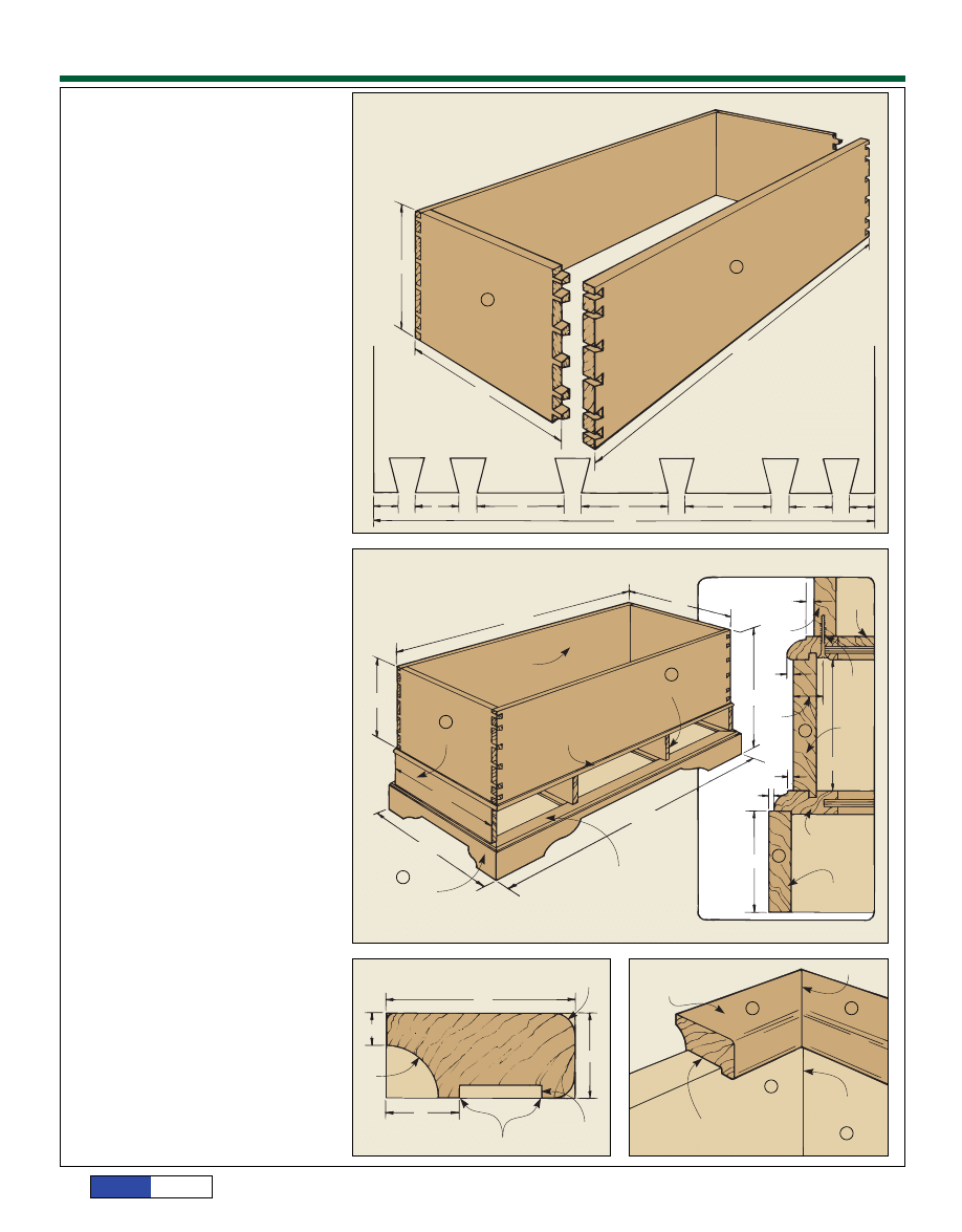
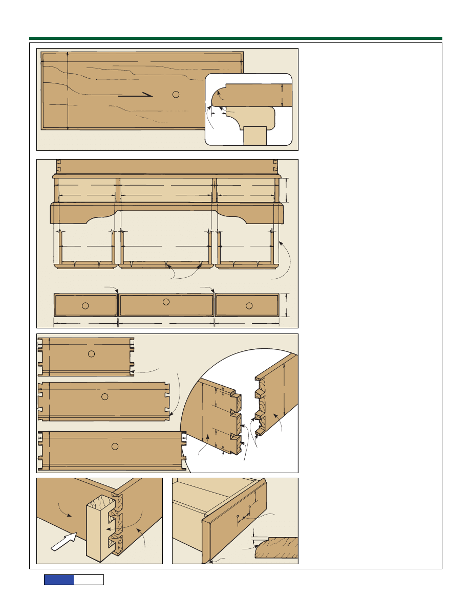
GLUING UP.
The first step is to glue up
enough stock to produce two solid-wood
panels for the front and back (I) with rough
dimensions of 12" x 42", and two panels for
the ends (J) with rough dimensions of 12"
x 17". (See page 13 for the step-by-step
procedure I used.)
After the panels are glued together, flat-
ten them using a hand plane or belt sander.
Then trim the panels for the front and back
to final dimensions of 11
1
/
2
" x 41
5
/
16
", and
the end panels to 11
1
/
2
" x 16
1
/
16
".
Note: So the dovetail corners can be
sanded flush after assembly, the measure-
ments given are
1
/
16
" longer than the final
dimensions of the box.
DOVETAILS.
I used the layout shown in
Fig. 14, and cut the dovetails using a router
jig. Of course, if the spirit moves you, the
dovetails can also be cut by hand. After
the dovetails are cut, the box is glued
together, and the dovetail corners are sand-
ed flush.
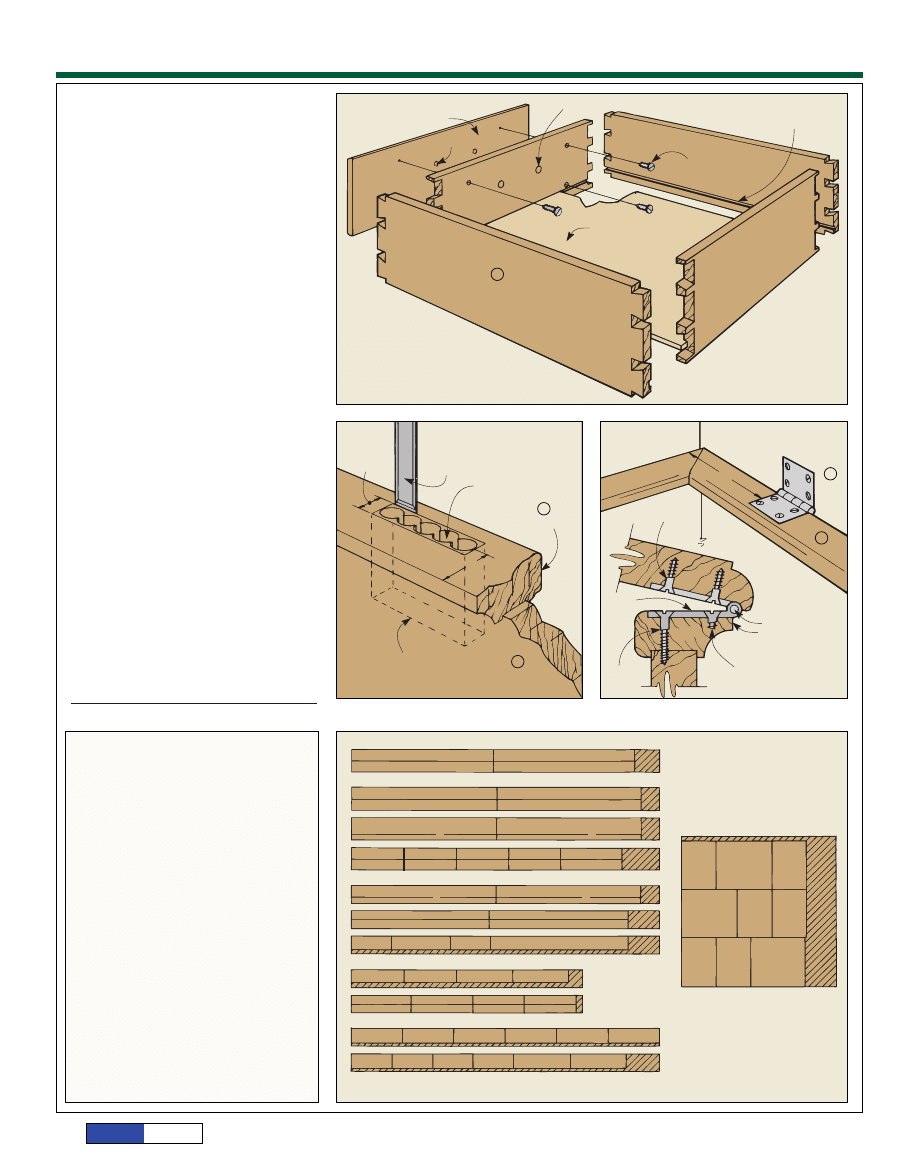
ASSEMBLY
Once the main box is glued together, the
drawer carcase is attached to the bottom
edge of the box.
UPPER FRAME.
The first step is to attach
the upper frame of the drawer carcase to
the box. To do this, center the molded edge
of the upper frame around the bottom edge
of the box, see Fig. 15. Then clamp the
frame to the box, and drill pilot holes for #8
x 1
1
/
4
" woodscrews 1
1
/
8
" from the outside
edge of the frame members. Finally, I
unclamped the frame, applied glue to the
bottom edge, and screwed the upper frame
to the box.
APRONS.
To assemble the rest of the
drawer carcase, glue the aprons (with the
splines in the mitered corners), the draw-
er dividers and the lower frame in place.
Note: Be sure to keep the front edges of the
drawer dividers and end aprons in line.
KICKBOARD.
After the drawer carcase
assembly has dried, the kickboard is glued
to the rabbet on the bottom edge of the
lower drawer carcase frame, see Fig. 15.
LIP MOLDING
With the bottom section completed, I
flipped the cabinet right side up and start-
ed on the lip molding for the top edge of the
box.
To make the lip molding, rip enough stock
1
3
/
4
" wide for all four sides of the box. Then
cut a
1
/
8
"-deep groove
5
/
8
" from the outside
edge of the molding, see Fig. 16. (Note:
Adjust the width of this groove to fit the
top edge of the cabinet.)
Next, rout a
1
/
2
" cove on the bottom out-
side edge of the lip molding, and remove the
sharp corners on the inside edges using a
1
/
4
" rounding over bit set at a very shallow
depth. Finally, miter the lip molding to fit
the rim of the box, and glue it in place, see
Fig. 17.
FIGURE 16
TOP LIP MOLDING
!/4”
ROUND OVER
1 ”
#/4
%/16”
!/2”
COVE
BIT
%/8”
ROUT TO WIDTH OF BOX SIDE
!#/16”
!/8” DEEP
I
J
L
K
FIGURE 17
TOP LIP MOLDING
MITER CORNER
GLUE AND CLAMP TO TOP EDGE
OF BOX ON ALL SIDES
INSIDE CORNER
H
F
D
FIGURE 15
1st ATTACH BOX TO UPPER FRAME
2nd ATTACH DRAWER CARCASE
3rd ATTACH KICKBOARD ASSEMBLY
41 ”
!/4
16”
BOX
11 ”
!/2
END APRON
UPPER FRAME
DRAWER DIVIDER
16 ”
!/2
18 ”
%/8
KICKBOARD
LOWER FRAME
43 ”
&/8
CROSS SECTION
!/4”
BOX
UPPER
FRAME
%/16”
21”
#8-
1 ”
!/2
1 ”
!/8
END
APRON
4 ”
!/2
#/16”
#/16”
LOWER FRAME
3 ”
!/2
KICKBOARD
D
H
I
J
FIGURE 14
BOX DIMENSIONS
NOTE: MEASUREMENTS INCLUDE AN
EXTRA
” IN LENGTH FOR
CUTTING DOVETAIL JOINT
!/16
11 ”
!/2
END
FRONT/BACK
41
”
%/16
16 ”
!/16
DOVETAIL DETAIL
%/8”
%/8”
#/8”
#/8”
#/8”
#/8”
#/8”
#/8”
1”
1”
2”
2”
2”
11 ”
!/2
Plans
N O W
page 5
© 1998, August Home Publishing Co.
THE LID
Even though the first thing most people
notice on a blanket chest is its lid, most
contemporary chests are sold with either
cushions covering the lid, or a little railing
around the perimeter.
For the lid on this chest, I decided to fol-
low the design found on most traditional
chests - a flat, solid-wood lid that’s simple
in design, and lets the beauty of the wood
speak for itself.
GLUING.
Since the lid overhangs the lip
molding
3
/
8
" on all four sides, the first step
is to glue up enough stock to produce a
panel that can be trimmed down to pro-
vide the
3
/
8
" overhang. Then the lid (M) is
planed flat, and trimmed to its final dimen-
sions.
MOLDING.
After the lid is trimmed to final
size, its outside edge is molded with a
1
/
2
"
rounding over bit, leaving a
1
/
8
" shoulder, see
Cross Section detail in Fig. 18. Then on the
bottom outside edge, the sharp edge is
removed using a
1
/
4
" rounding over bit set
at a very shallow depth of cut.
THE DRAWERS
One of the things that makes this chest dif-
ferent from its modern counterparts are
three functional drawers. The drawers are
built in two sections; the four-sided draw-
er, and the false fronts that are molded to
match the design of the chest.
DRAWERS.
The first step is to cut the
1
/
2
"
drawer stock for the fronts and backs (N
and O) to fit between the drawer runners,
and
1
/
16
" narrower than the height of the
openings. Then cut the sides of the draw-
ers (P) 15" long (for a 1" clearance at the
back of the drawer), and to the same width
as the drawer fronts.
JOINERY.
To keep the joinery consistent,
I used through dovetails routed with a jig
(the spacing is shown in Fig. 20). (Note:
These drawers could also be joined with
half blind dovetails using the standard
router fixtures reviewed in Woodsmith No.
22.)
After completing the corner joinery, cut
a
1
/
4
" groove for the drawer bottom (Q and
R)
3
/
8
" from the bottom edge, see Fig. 20.
BOTTOM.
Finally, dry clamp the drawers
together and measure the groove-to-groove
openings for the drawer bottoms. Then cut
the
1
/
4
" Masonite bottoms to fit, and glue
the drawers together with the drawer bot-
toms in place. (Shop Note: To apply clamp-
ing pressure to the tails, I used the clamp-
ing block shown in Fig. 21.)
FALSE FRONTS.
Each drawer has a
13
/
16
"-
thick false front that’s attached directly to
the drawer front. To find the dimensions for
the large false front (S), measure from cen-
ter to center on the drawer dividers, see
Fig. 19. Then cut the large false front to
this length, and to the same height as the
drawers.
M
FIGURE 18
43 ”
!/4
18”
LID
GRAIN DIRECTION
CROSS SECTION
!/2
!/8
” ROUND OVER
WITH
” SHOULDER
!#/16”
#/8” OVERHANG
ON ALL EDGES
#/8”
ROUND OVER
BOTTOM EDGE
SLIGHTLY
BOX
S
T
T
FIGURE 19
FRONT VIEW CHEST
12 ”
!/16
12 ”
!/16
18”
11”
11”
11”
11”
16
”
!%/16
16
”
!%/16
4 ”
!/2
TOP VIEW DRAWERS
SCREW FALSE FRONT
TO DRAWER
ALIGN OUTSIDE EDGE
OF DRAWER FRONT
WITH OUTSIDE EDGE
OF APRON
!/16” SPACE
!/16” SPACE
FALSE FRONTS
12”
12”
18”
4 ”
&/16
N
O
P
11”
4 ”
&/16
SMALL DRAWER FRONT/BACK
(2 PIECES)
15”
4 ”
&/16
SIDES
(6 PIECES)
16
”
!%/16
4 ”
&/16
LARGE DRAWER FRONT/BACK
(2 PIECES)
DRAWER DIMENSIONS
GROOVE
”
FROM BOTTOM
” WIDE,
” DEEP
ON ALL PIECES
#/8
!/4
#/16
FIGURE 20
DOVETAIL DETAIL
%/16”
%/16”
1 ”
#/8
1 ”
#/8
4 ”
&/16
4 ”
&/16
SIDE
TAILS
PINS
FRONT/BACK
FIGURE 21
SIDE
DOVETAIL
CLAMPING
BLOCK
FRONT/BACK
CLAMP PRESSURE
DIRECTION
FIGURE 22
CENTERED
ON
DRAWER
FRONT
1 ”
#/4
2 ”
!/2
!/8” SHOULDER
CROSS SECTION
!/2”
ROUNDING
OVER BIT
Plans
N O W
page 6
© 1998, August Home Publishing Co.
To find the lengths for the small drawer
fronts (T), measure the distance from the
center of the drawer dividers to the outside
edge of the side apron, and subtract
1
/
16
"
for clearance, see Fig. 19. Then cut the two
small false fronts to length, and to the same
height as the drawers.
MOLDING.
The outside edges on the false
fronts are routed with a 1/2" rounding over
bit to match the moldings on the cabinet,
see Fig. 22. Then I attached the large false
front centered on the large drawer, and the
small drawer fronts so they’re flush with
the outside face of the end aprons, see Fig.
23.
HARDWARE
DRAWER PULLS.
The drawer pulls I used
are centered on the width, 1
3
/
4
" down from
the top edge of the drawer fronts, and the
screw holes are counter-bored from the
back, see Fig. 22.
LOCK.
To mount the full mortise lock, I
drilled a series of
3
/
8
" holes 1" from the front
edge of the lip molding, see Fig. 24. Then
the hole for the key is drilled, and the
escutcheon is mounted over the key hole.
HINGES.
When mounting the special
hinges (that are designed for the excessive
overhang of the lid), mortise them into both
the lip molding and the lid, see Fig. 25.
Then I added an optional lid support to pre-
vent the lid from slamming shut.
KITS.
Woodsmith Project Supplies is
offering three hardware kits which include
hinges, a lid support, and drawer pulls. Call
1-800-444-7002 for more information.
FINISH.
I applied two coats of tung oil
sealer, and four coats of medium luster tung
oil. Note: Be sure not to finish the cedar, or
you’ll reduce its aromatic characteristic.
MATERIALS LIST
CUTTING DIAGRAM
Overall Dim.: 22
1
/
2
"
H x 18
5
/
8
"
W - 43
7
/
8
"
L
A End Stiles (4)
13
/
16
x 2
1
/
4
- 18
1
/
4
B Center Stiles (4)
13
/
16
x 2
1
/
4
- 14
3
/
4
C Frt/Bk Rails (4)
13
/
16
x 2
1
/
4
- 43
1
/
2
D End Aprons (2)
13
/
16
x 5 - 16
1
/
2
E Back Apron (1)
13
/
16
x 5 - 42
1
/
8
F Drawer Dividers (2)
13
/
16
x 5 - 15
15
/
16
G Kickboard Frt/Bk (2)
13
/
16
x 3
1
/
2
- 43
7
/
8
H Kickboard Ends (2)
13
/
16
x 3
1
/
2
- 18
5
/
8
I Box Frt/Bk (2)
13
/
16
X 11
1
/
2
- 41
1
/
4
J Box Ends (2)
13
/
16
X 11
1
/
2
- 16
K Top Lip Frt/Bk (2)
13
/
16
X 1
3
/
4
- 42
1
/
2
L Top Lip Ends (2)
13
/
16
X 1
3
/
4
- 17
1
/
4
M Lid (1)
13
/
16
X 17
7
/
8
- 43
1
/
4
N Sm Drawer Frt/Bk (4)
1
/
2
x 4
7
/
16
- 11
O Lg Drawer Frt/Sk (2)
1
/
2
x 4
7
/
16
- 16
15
/
16
P Drawer Sides (6)
1
/
2
x 4
7
/
16
- 15
Q Sm Drawer Bottom (2) cut to fit
R Lg Drawer Bottom (2) cut to fit
S Lg False Front (1)
13
/
16
x 4
7
/
16
- 18
T Sm False Front (2)
13
/
16
x 4
7
/
16
- 12
U End Panel (4)
1
/
4
x 10
3
/
8
- 14
3
/
4
V Center Panel (2)
1
/
4
x 16
3
/
4
- 14
3
/
4
W Aromatic Red Cedar
cut to fit
P
FIGURE 23
FALSE FRONT
DRILL
” HOLE FOR HARDWARE
!/2
!/4
#/16
” GROOVE,
” DEEP
#/16”
FRONT
#8 - 1” WOODSCREW
!/4” MASONITE BOTTOM
SIDE
BACK
I
K
FIGURE 24
FINAL
WIDTH
”
&/16
CHISEL
LOCK MORTISE DETAIL
USE
” DRILL BIT
#/8
LIP MOLDING
BOX
MORTISE 2” DEEP
1”
M
K
FIGURE 25
HINGE ATTACHMENT
5”
#8 x
”
BRASS SCREW
%/8
BOX
HINGE
POSITION HINGE
PIN JUST BEYOND
EDGE OF LIP
CUT OFF SHANK
#8 x 1”
BRASS
SCREW
!#/16
!/4
” x 7 ” -- 96” (2 BOARDS)
!#/16
!/4
” x 7 ” -- 96”
!#/16
!/2
” x 5 ” -- 96”
!#/16
!/2
” x 5 ” -- 72”
!/2
!/2
” x 5 ” -- 96”
48” x 48” --
” MASONITE
!/4
I
I
I
I
M
M
M
M
M
M
K
K
J
J
J
J
J
J
J
J
H
H
G
G
L
L
C
C
C
C
T
T
S
E
F
F
D
D
A
A
A
A
B
B
B
B
P
P
P
P
P
P
N
N
N
N
O
O
U
U
U
U
V
V
Q
Q
R
Wyszukiwarka
Podobne podstrony:
Abolicja podatkowa id 50334 Nieznany (2)
4 LIDER MENEDZER id 37733 Nieznany (2)
katechezy MB id 233498 Nieznany
metro sciaga id 296943 Nieznany
perf id 354744 Nieznany
interbase id 92028 Nieznany
Mbaku id 289860 Nieznany
Probiotyki antybiotyki id 66316 Nieznany
miedziowanie cz 2 id 113259 Nieznany
LTC1729 id 273494 Nieznany
D11B7AOver0400 id 130434 Nieznany
analiza ryzyka bio id 61320 Nieznany
pedagogika ogolna id 353595 Nieznany
Misc3 id 302777 Nieznany
cw med 5 id 122239 Nieznany
D20031152Lj id 130579 Nieznany
mechanika 3 id 290735 Nieznany
więcej podobnych podstron