
30.11.2005
imnot50
1
Earthing
Earthing
Arrangeme
Arrangeme
nts
nts

30.11.2005
imnot50
2
Earthing arrangements - always a good
talking point!

30.11.2005
imnot50
3
Definitions from Part 2 BS 7671
Definitions from Part 2 BS 7671

30.11.2005
imnot50
4
Bonding conductor
A protective conductor
providing equipotential
bonding
30.11.2005
imnot50
5
Where protection against electric shock does not rely
solely on basic insulation alone. Exposed-conductive
parts being connected to a protective conductor within
the fixed wiring of the installation.
Class I equipment
Class I insulation
Single-layer insulation
Live part
Exposed conductive
part
30.11.2005
imnot50
6
Class II equipment
Where protection against electric shock relies
on the
application of additional or supplementary
insulation.
There is no provision for the connection of a
protective
conductor
to exposed metalwork.
Class II insulation
Live part
Two layers of
insulation
Exposed metalwork

30.11.2005
imnot50
7
Double insulation
Double insulation (Class II) - Insulation
comprising both basic insulation and
supplementary insulation

30.11.2005
imnot50
8
Earth
The conductive mass of Earth, whose
electric potential at any point is
conventionally taken as zero

30.11.2005
imnot50
9
Earth Electrode
A conductor or group of conductors
in intimate contact with, and providing
an electrical connection to earth

30.11.2005
imnot50
10
Earth electrode
resistance
The resistance of an earth
electrode to earth

30.11.2005
imnot50
11
Earth fault current
A fault current which flows to earth

30.11.2005
imnot50
12
Earth fault loop
impedance
The impedance of the earth fault current
loop starting and ending at the point of
earth fault.
Symbol Z
Symbol Z
Unit
Unit

30.11.2005
imnot50
13
The earth fault loop
The earth fault loop starting at the point of
fault
consists of:
• The circuit protective conductor (c.p.c.)
• Consumers earthing terminal and earthing conductor
• For TN systems, the metallic return path
• For TT and IT systems the earth return path
• The path through the earthed neutral point
of the
transformer
• The transformer winding and phase conductor to point
of fault

30.11.2005
imnot50
14
Earth leakage current
A current which flows to earth, or
to
extraneous conductive parts, in a
circuit
which is electrically sound. This
current
may have a capacitive including
that from
the deliberate use of capacitors.
Deleted by BS
671:2001

30.11.2005
imnot50
15
Leakage
current
Electric current in an unwanted conductive
path under normal operating conditions
NEW

30.11.2005
imnot50
16
Electric current which flows in a protective
Conductor under normal operating conditions
NEW
Protective conductor current

30.11.2005
imnot50
17
Earthed equipotential
zone
A zone within which exposed conductive parts and
extraneous conductive parts are maintained at
substantially the same potential by bonding, such
that under fault conditions, the differences in potential
simultaneously accessible exposed and extraneous-
conductive parts will not cause electric shock.

30.11.2005
imnot50
18
Earthing
Connection of the exposed conductive
parts
of an installation to the main earthing
terminal of that installation

30.11.2005
imnot50
19
Direct contact (shock)
Results from
Making contact with parts of a circuit
Making contact with parts of a circuit
or
or
system which are live under normal
system which are live under normal
conditions
conditions

30.11.2005
imnot50
20
Earthing
Connection of the exposed conductive
parts of an installation to the main earthing
terminal of that
installation

30.11.2005
imnot50
21
Extraneous conductive
part
A conductive part liable to introduce a
potential, generally earth potential, and not
forming part of the electrical installation.

30.11.2005
imnot50
22
Fault
A circuit condition in which current flows through an
abnormal or unintended path. This may result from an
insulation failure or a bridging of insulation. Conventionally
the impedance between live conductors or between live
conductors and exposed or extraneous conductive parts
at the fault position is considered negligible.

30.11.2005
imnot50
23
Functional earthing
Connection to Earth necessary for proper
functioning of electrical equipment
Table 51A
Table 51A
Functional earthing conductors
to be
coloured cream

30.11.2005
imnot50
24
Contact of persons or livestock with
exposed-conductive parts which have
become live under fault conditions.
Indirect contact

30.11.2005
imnot50
25
Protective conductors
A conductor used for some measure of protection against
electric shock and intended for connecting together any
of the following parts
• Exposed conductive parts
• Extraneous-conductive parts
• The main earthing terminal
• Earth electrode(s)
• The earthed point of the source, or an artificial neutral
30.11.2005
imnot50
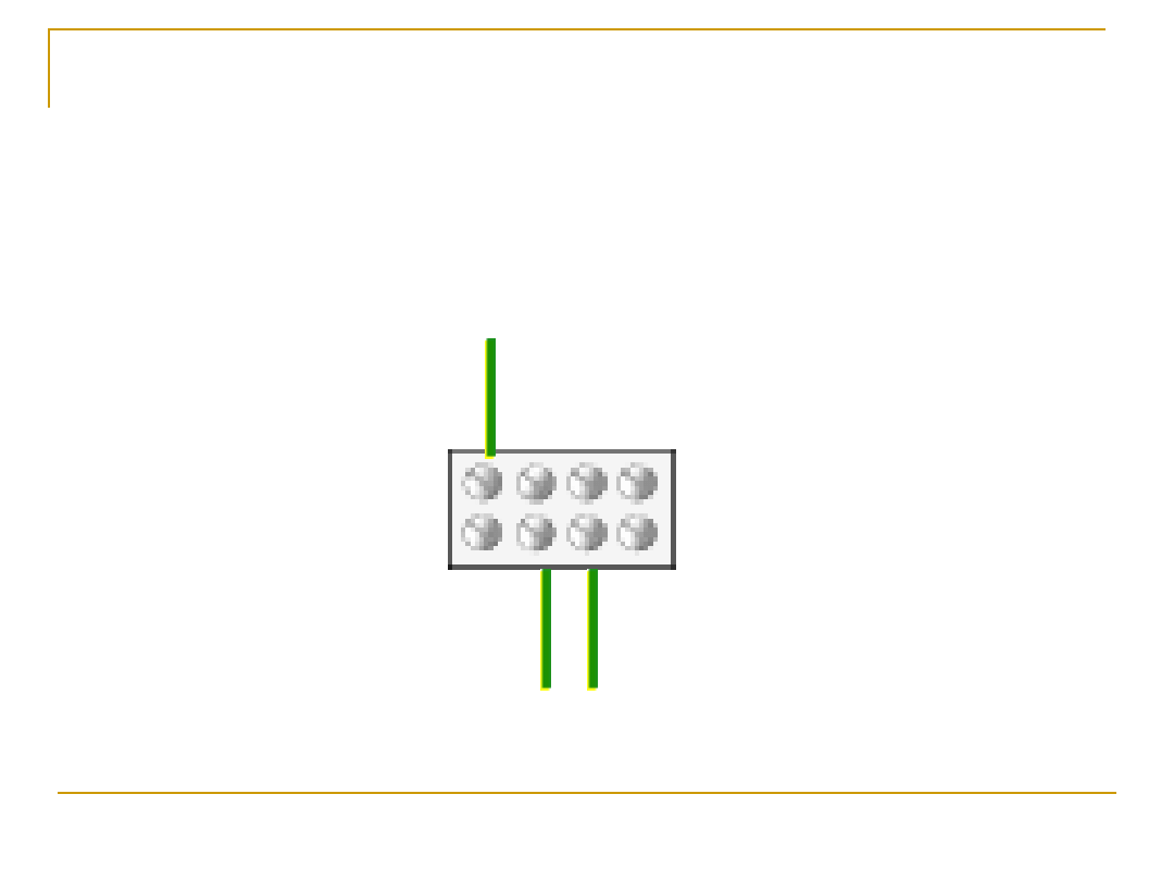
26
Protective conductors
Earthing conductor
main bonding
conductor
circuit protective
conductor

30.11.2005
imnot50
27
Shock conditions
Shock conditions

30.11.2005
imnot50
28
Direct contact
Contact of persons or livestock with
live parts
30.11.2005
imnot50
29
Uo = 230V
Direct
contact
(shock)
ouch
ouch

30.11.2005
imnot50
30
Direct Contact
Maximum shock voltage
Maximum shock voltage
No disconnection
No disconnection

30.11.2005
imnot50
31
Protection against Direct
contact (shock)
Insulation
Insulation
Barriers
Barriers
Enclosures
Enclosures

30.11.2005
imnot50
32
Protection against Direct contact (shock)
Placing out of
Placing out of
reach
reach
Obstacles
Obstacles
Protection of a specialist nature
Protection of a specialist nature
30.11.2005
imnot50
33
Uo = 230V
Indirect contact (shock)
Automatic operation of protective device
Automatic operation of protective device
Reduced shock risk
Reduced shock risk

30.11.2005
imnot50
34
Protection against indirect
contact (shock)
E
arthed
E
quipotential
B
onding
A
nd automatic
D
isconnection
O
f
S
upply

30.11.2005
imnot50
35
Earthing
Earthing
Arrangements
Arrangements
30.11.2005
imnot50
36
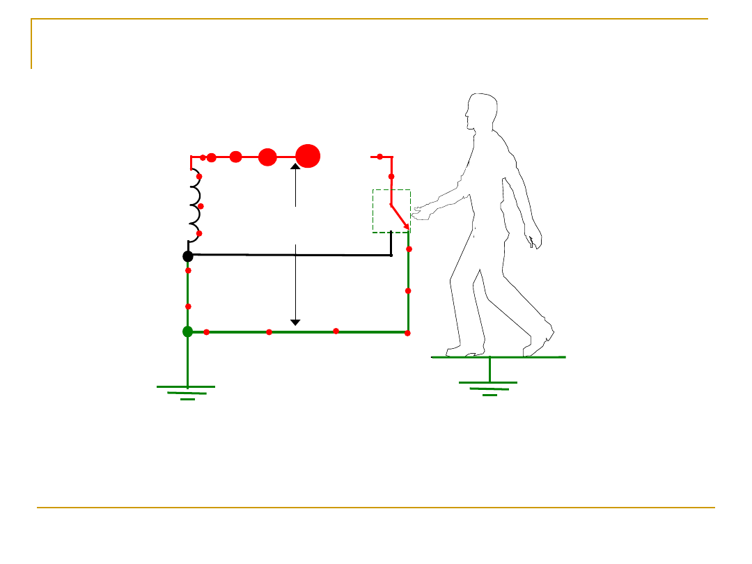
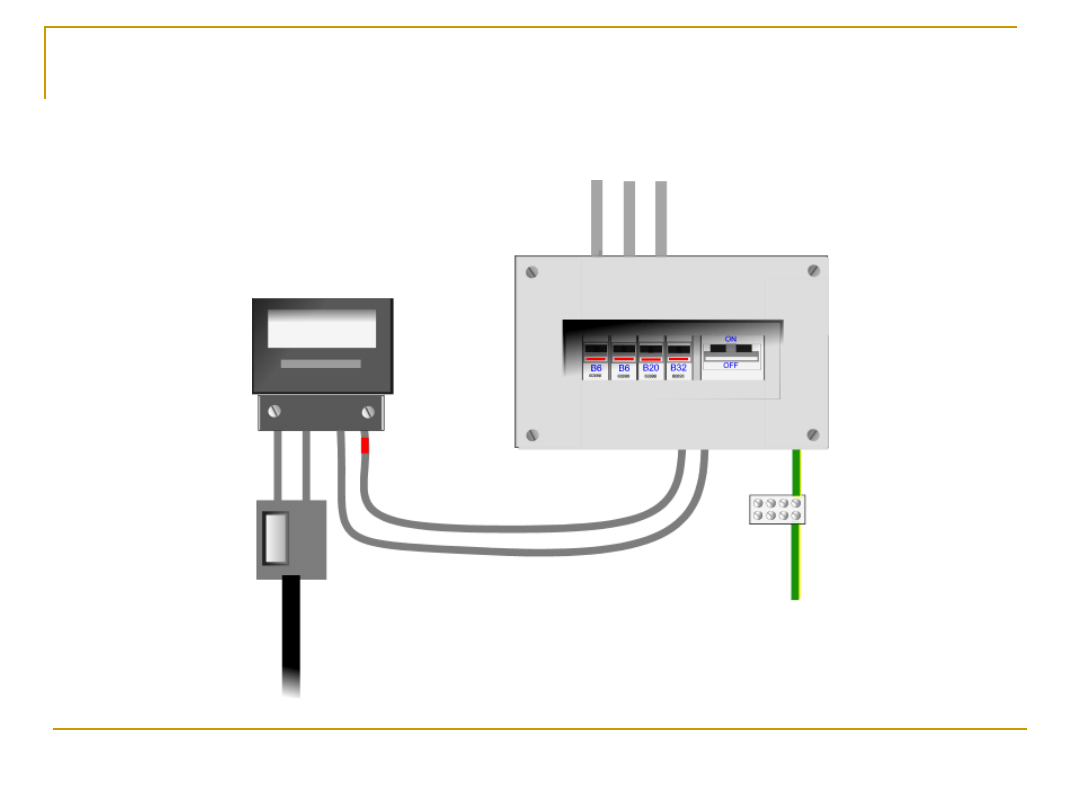
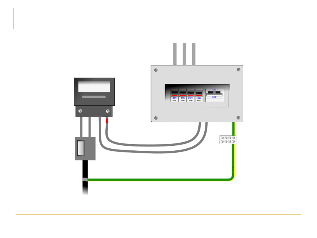
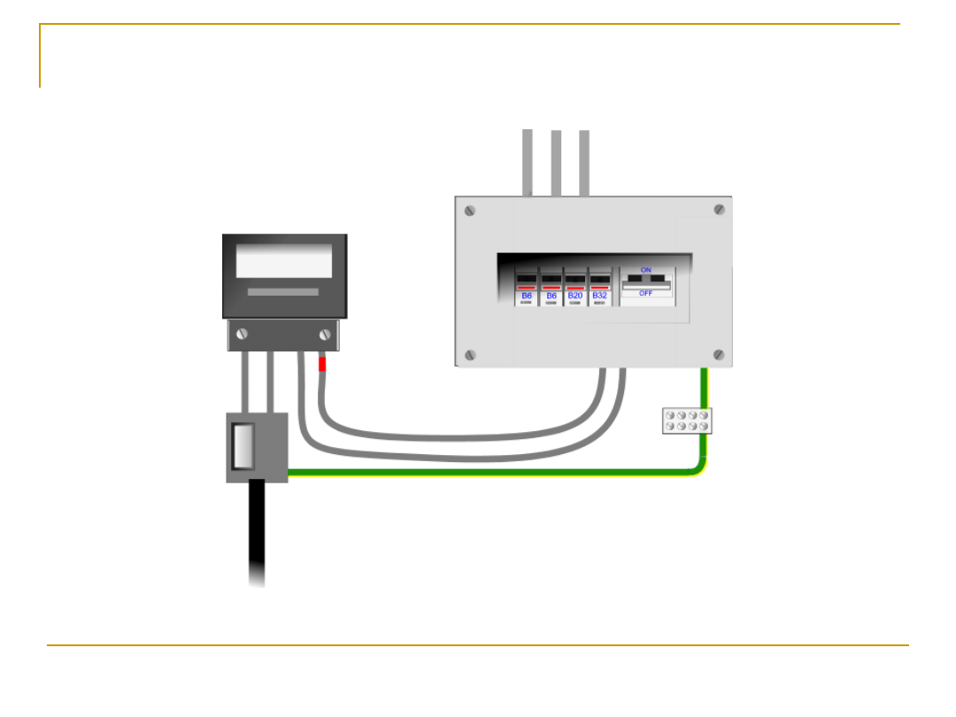
TT Earthing
Arrangement
PES
cut out
P.E.S
metering
earthing
conductor
from overhead supply
to earth electrode
consumer unit

30.11.2005
imnot50
37
1st Letter
- Method of earthing for
suppliers network
2nd Letter
-
Method of earthing at consumers
installation
T = Direct connection to earth at one or
more points
T = Direct connection to earth
30.11.2005
imnot50
38
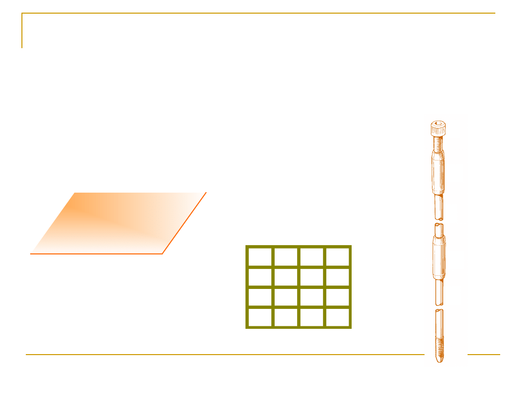
Frequently used types of
earth electrode
plate
lattice
rod
Regulation 542-
Regulation 542-
02-01
02-01

30.11.2005
imnot50
39
Earth electrodes recognised by BS 7671
Earth electrodes recognised by BS 7671
The following types of earth electrode are recognised by the
Regulations:
Regulation 542-02-01
Earth rods or pipes
Earth tapes or wires
Earth plates
Underground structural metalwork embedded in
foundations
Welded metal reinforcement of concrete (except
pre-stressed concrete) embedded in earth
Lead sheaths and other metal coverings of cables
where not precluded by regulation 542-02-05
Other suitable underground metalwork

30.11.2005
imnot50
40
Installation of earth electrodes
When installing earth electrodes the following
precautions should be observed
Regulation 542-02-02
Remember climatic conditions could affect
electrode resistance
The type and embedded depth of an earth
electrode shall be sufficient to avoid soil
drying and freezing
30.11.2005
imnot50
41
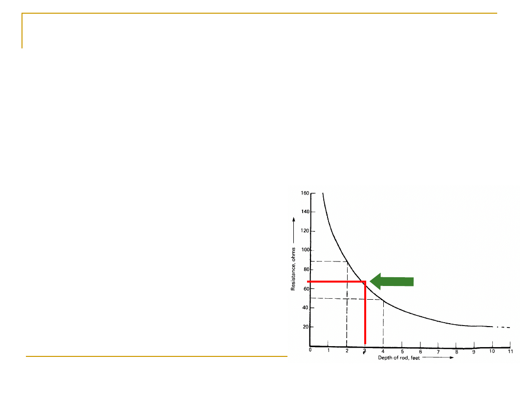
Earth electrode
resistance
The graph illustrates the relationship between
electrode resistance and buried depth for a ‘rod
type’ electrode. The deeper the rod, the closer to
the water table it becomes, resulting in lower
resistance
Typical value of resistance of
‘rod type’ electrode buried to
a depth of 1 metre (60
approx.)

30.11.2005
imnot50
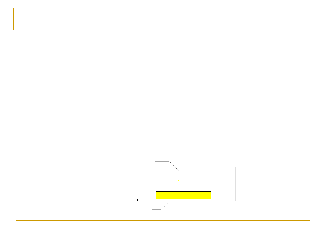
42
Reducing earth electrode resistance
Reducing earth electrode resistance
Under certain circumstances the value of
electrode resistance may be excessively high
and steps must be taken to reduce its value.
The following methods may be adopted:
•
use of extendable rods
• use of additional rods
• soil conditioning agents (temporary
measure)
• electrodes buried to a greater
depth
30.11.2005
imnot50
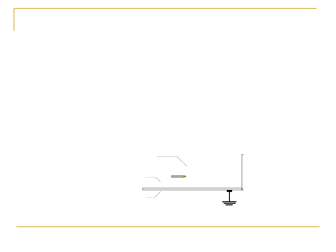
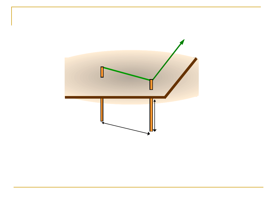
43
Use of additional rods to reduce
resistance
Distance (m)
Depth (m)
As a ‘rule of thumb’, the distance between
adjacent earth rods should not be less than the
buried depth.
Earthing
conductor

30.11.2005
imnot50
44
Problems associated with the TT
system
Vulnerable to mechanical damage
Vulnerable to corrosion
High resistance as compared
High resistance as compared
to TN systems
to TN systems

30.11.2005
imnot50
46
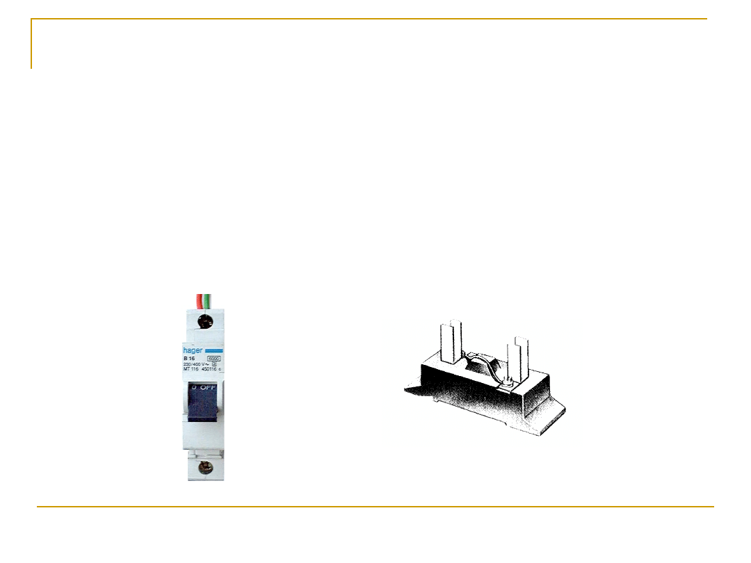
Use of the residual current device
Regulation 413-02-19
Preferred method of protection against
indirect contact, by means of residual
current device.

30.11.2005
imnot50
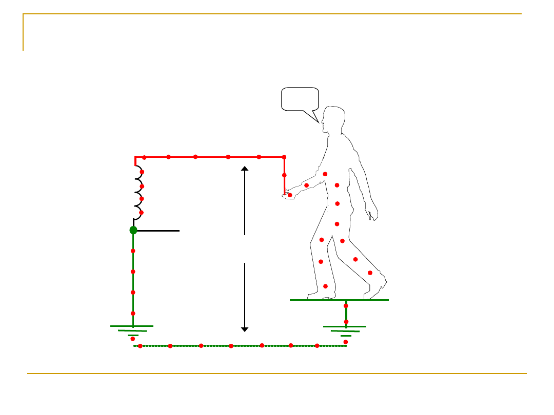
47
Calculating touch voltage
Maximum permitted touch voltage = 50V unless
special location. (max 25V)
Regulation 413-02-20

30.11.2005
imnot50
48
The following condition must be
fulfilled:
R
R
A.
A.
I
I
n
n
50V.
50V.
Where:
R
R
A
A
is the sum of the earth electrode and protective
conductors connecting it to the exposed-conductive parts
I.
I.
n
n
is the current causing automatic operation
of the r.c.d.

30.11.2005
imnot50
49
REMEMBER
50V
max, or
25V
max
30.11.2005
imnot50
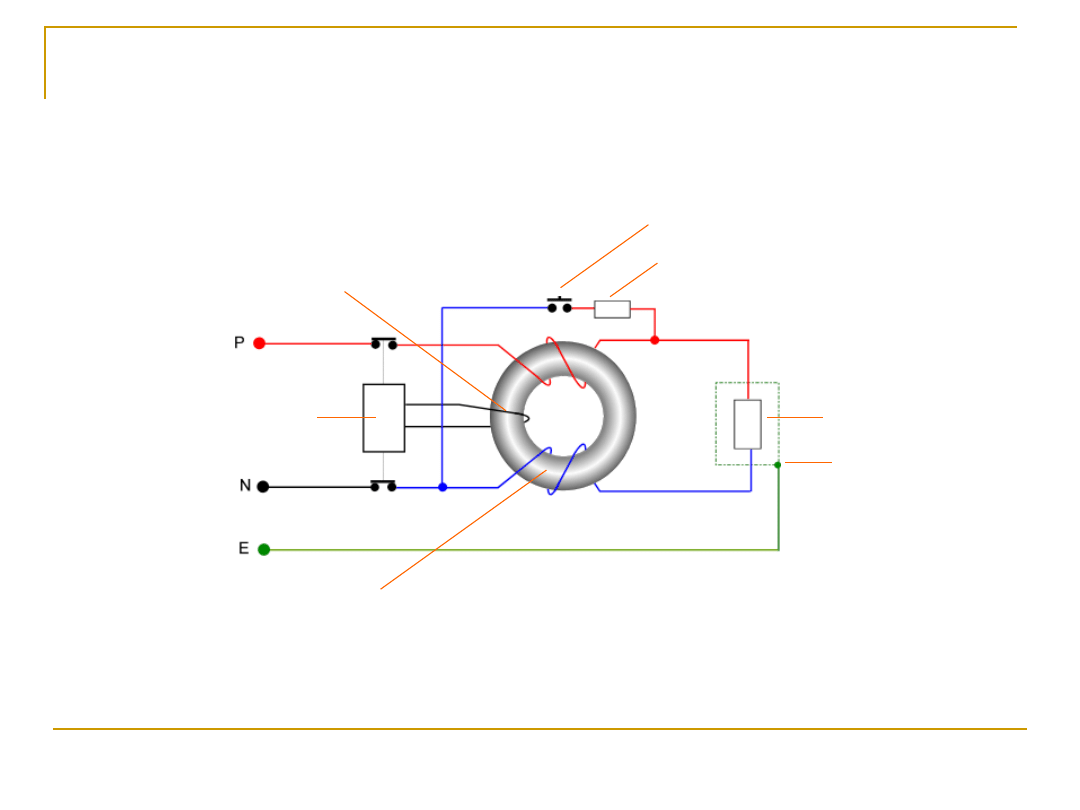
50
Load
Load
Exposed
Exposed
metalwork
metalwork
Test resistor
Test resistor
Test button
Test button
Search coil
Search coil
Toroid
Toroid
Operating
Operating
coil
coil
The residual
current
current
device
device
30.11.2005
imnot50
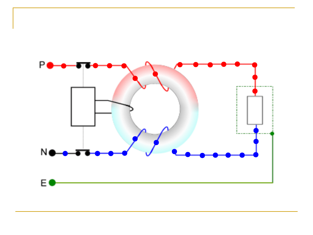
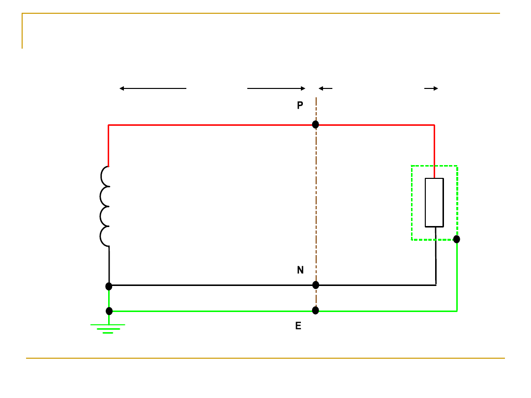
51
The R.C.D under healthy circuit
conditions
30.11.2005
imnot50
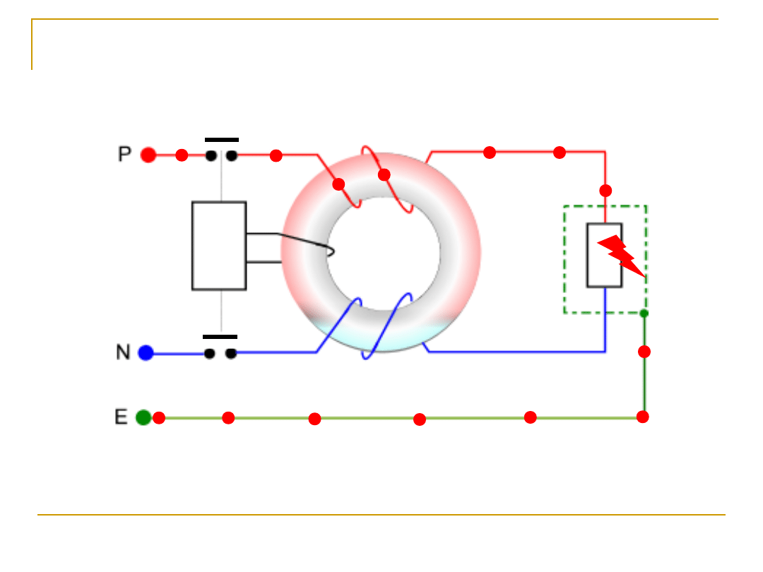
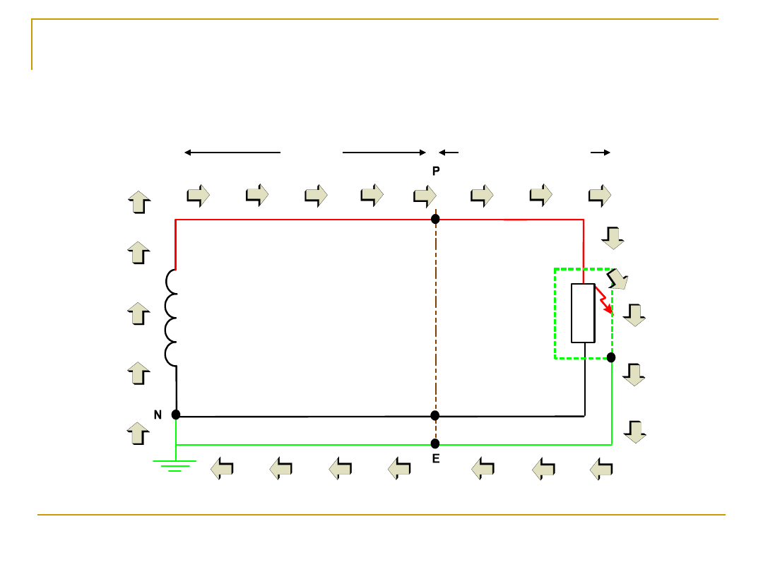
52
The R.C.D under earth fault
conditions
30.11.2005
imnot50
53
Protection and the TT system
Remember!
The earth fault loop impedance for a TT system
may be too high to allow circuit breakers and fuses to
operate under phase to earth fault conditions.

30.11.2005
imnot50
54
Solution
R.C.D.
30.11.2005
imnot50
55
TN-S Earthing Arrangement
Separate neutral and earth conductors

30.11.2005
imnot50
56
1st Letter -
Method of earthing for suppliers
network
2nd Letter -
Method of earthing at
consumers installation
T = Direct connection to earth at one or
more points
N = Consumers exposed metalwork
directly connected to the earthed neutral
point of the supply
3rd Letter -
Relationship between phase &
neutral conductors on suppliers network
S = Separate neutral and earth conductors
at consumers
installation
30.11.2005
imnot50
57
Fig. 7
PES
consumer
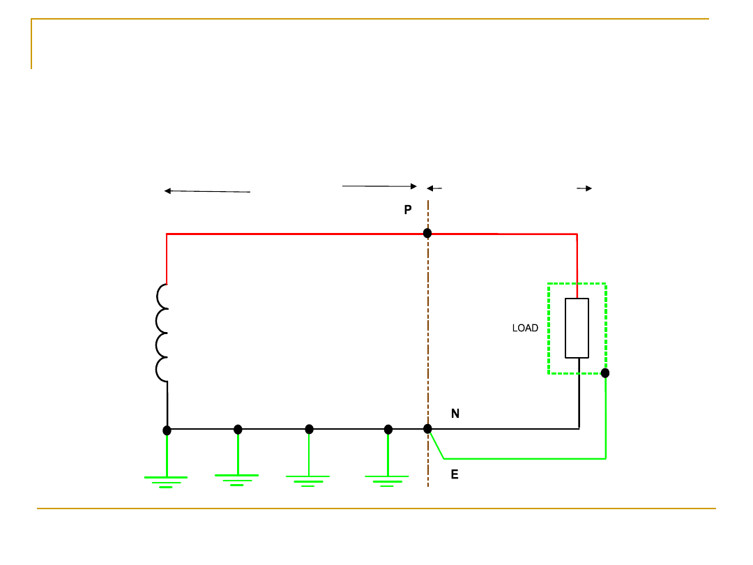
The circuit arrangement for the TN-S
system
30.11.2005
imnot50
58
PES
consumer
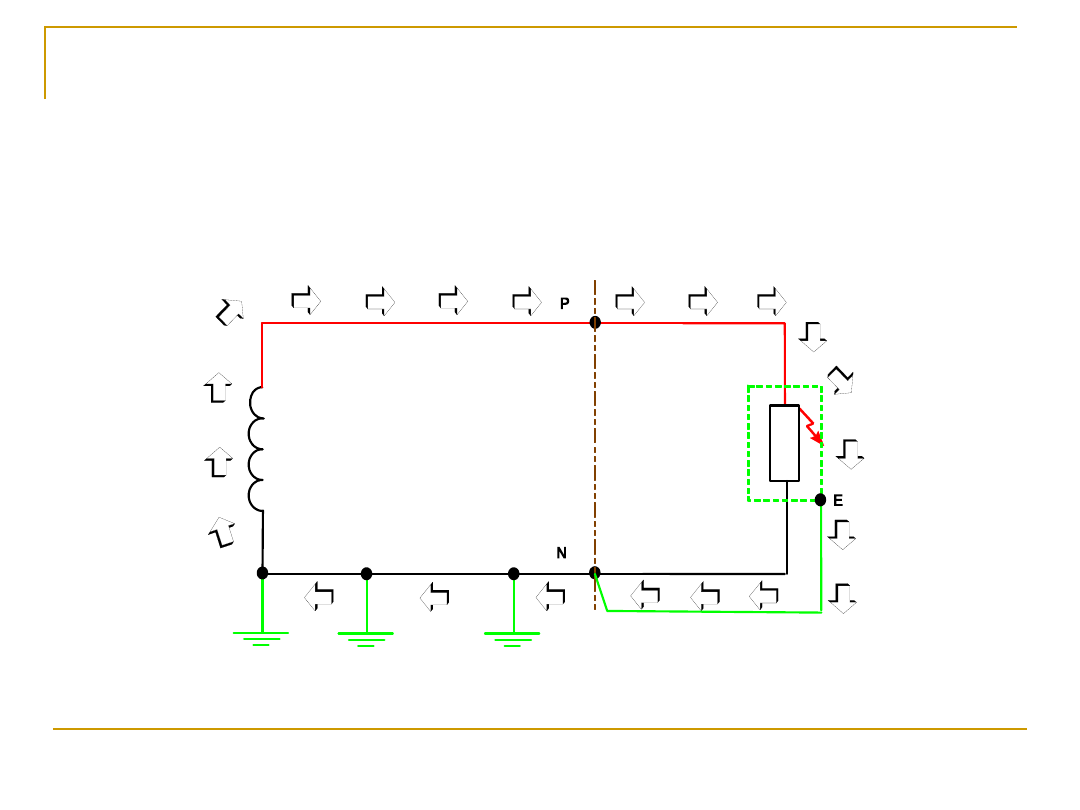
The TN-S system under fault
conditions
30.11.2005
imnot50
59
TN-C-S Earthing Arrangement
combined neutral and earth conductors

30.11.2005
imnot50
60
1st Letter -
Method of earthing for suppliers
network
2nd Letter -
Method of earthing at
consumers installation
T = Direct connection to earth at one or
more points
N = Consumers exposed metalwork
directly connected to the earthed neutral
point of the supply
3rd Letter -
Relationship between phase &
neutral conductors on suppliers network
C = Combined neutral and earth on
suppliers side
4th Letter -
Arrangement of earth and
neutral conductors at consumers installation
S = Separate neutral and earth
conductors at consumers installation
30.11.2005
imnot50
61
PES
consumer
PEN conductor
The circuit arrangement for the TN-C-S system
30.11.2005
imnot50
62
The TN-C-S system under fault
conditions
Document Outline
- Earthing Arrangements
- Slide 2
- Slide 3
- Slide 4
- Slide 5
- Slide 6
- Slide 7
- Slide 8
- Slide 9
- Slide 10
- Slide 11
- Slide 12
- Slide 13
- Slide 14
- Slide 15
- Slide 16
- Slide 17
- Slide 18
- Slide 19
- Slide 20
- Slide 21
- Slide 22
- Slide 23
- Slide 24
- Slide 25
- Slide 26
- Slide 27
- Slide 28
- Slide 29
- Slide 30
- Slide 31
- Slide 32
- Slide 33
- Protection against indirect contact (shock)
- Slide 35
- Slide 36
- Slide 37
- Slide 38
- Slide 39
- Slide 40
- Slide 41
- Slide 42
- Slide 43
- Slide 44
- Slide 46
- Slide 47
- Slide 48
- Slide 49
- Slide 50
- Slide 51
- Slide 52
- Slide 53
- Slide 54
- Slide 55
- Slide 56
- Slide 57
- Slide 58
- Slide 59
- Slide 60
- Slide 61
- Slide 62
Wyszukiwarka
Podobne podstrony:
WEEK 8 Earthing Calculations
WEEK 8 Earthing Calculations
40 0610 013 05 01 7 General arrangement
Six Week Programme
1 0 Get A Girlfriend In A Week
P000827 C Eng General arrangement W0064
Dni tygodnia FLASH?YS week
Turn Off TV Week
1 2 1 Girlfriend in A Week Checklists
what is your?vourite?y of the week
Orange arrangement flowers id 3 Nieznany
Week, seasons, months
WEEK 10 2391 Revision Questions 2
A typical Englishman's week
harmonogram business week - w, Ekonomia
Joke of the week
Week 6 OS for Wireless Mobile Devices
islcollective?ys of the week)0414c0f7dce5737c5C726116
więcej podobnych podstron