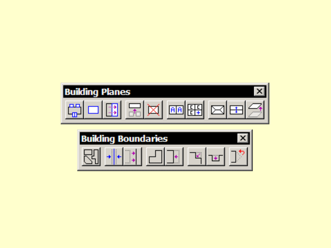
Building Vectorization
Tools
Arttu Soininen
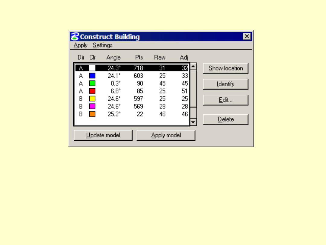
Plane list
• Direction group letter
• Boundary color
• Slope angle
• Number of points matching plane
• Average mismatch (mm) from point to raw plane
• Average mismatch (mm) from point to adjusted
plane
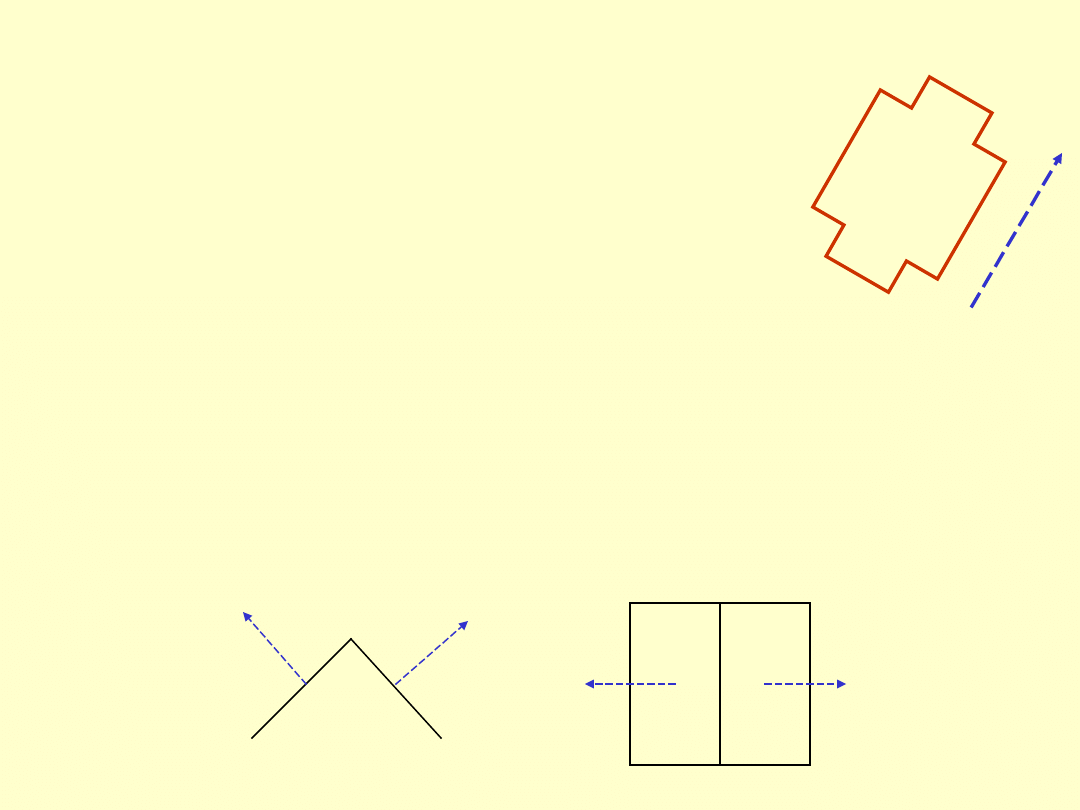
Plane direction
• Each plane has a base direction
– direction group has a common base direction
• Base direction affects:
– surface equation -- aligns normal vector
– boundary lines -- aligned if
rectangle/rectangular
• Direction vector is computed:
– from normal vector for sloped planes -- accurate
– from point cloud for flat planes -- less accurate
D
ir
ec
ti
on
Section
Top

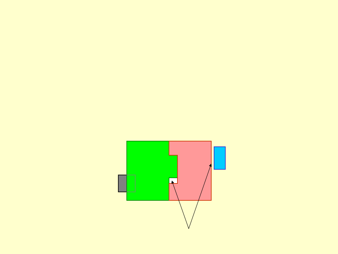
Identifying a plane
• Mouse click identifies a plane:
– inside which the mouse is
– closest to the viewer if multiple
• Use tentative on boundary
element to identify a plane behind
another
• Tools which accept 1-n planes:
– click inside a plane to add
– reset to reject the last one
– click outside all planes to complete
Aerial fill
• Before applying model
– no gaps between planes
– lower planes may extend inside higher
planes
Need to fix
Workflow order
• Reach correct number of planes
• Fix base directions
• Assign symmetry
• Set boundary types
Modify boundary shapes
Auto Align boundaries
• Apply model
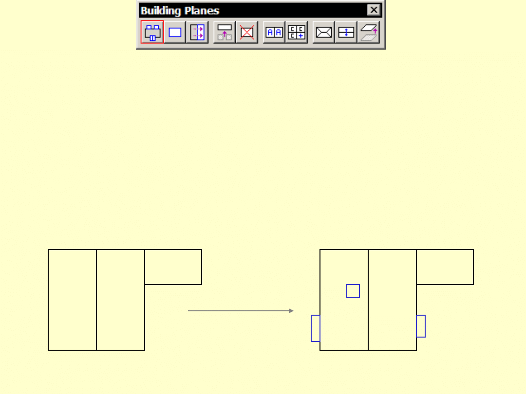
Find Detail Planes
• Searches for additional planes
among points
• More eager to accept small planes
• Use if you see small, undetected
parts

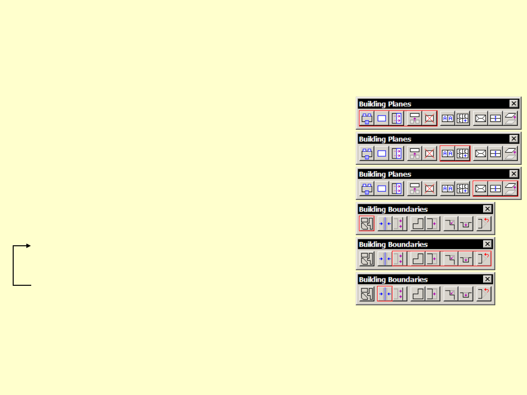
Add Building Plane
• Add building plane by:
– placing boundary manually
– using a selected existing element
• Equation can come from:
– free points inside boundary
– boundary
• Use when:
– application has not found correct planes
– alternative vectorization methods have
been used methods
Mirror Building Plane
• Create new plane as mirror image of
another
• Use when missing plane lacks points
1
2
3
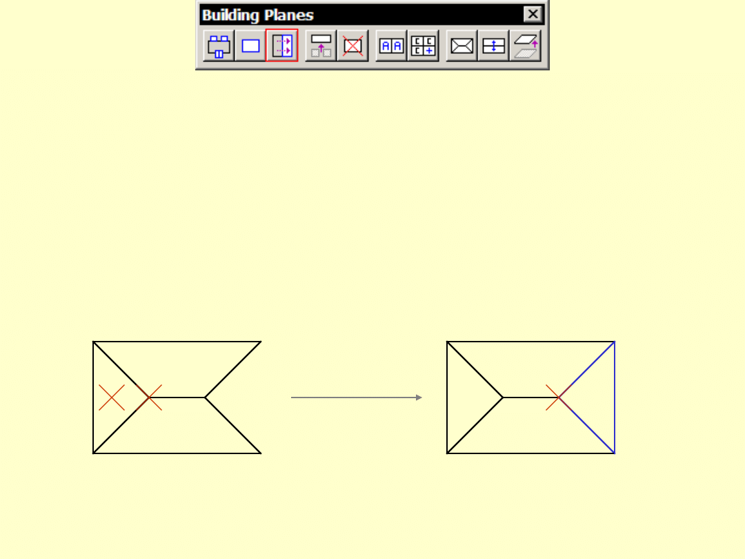
Merge Building Planes
• Merge two planes into one
– check first that equations are close
• Use when you want to:
– simplify by combining two
neighbouring planes
– merge two disjoint parts
Delete Building Plane
• Delete a building planes
• Laser points become ‘Free points’

Create Direction Group
• Assign 1-n planes to a new
direction group
• Base direction can be:
– line given by two points
– base direction of first plane
– average of assigned planes
Add Plane To Group
• Add plane(s) to an existing
direction group
• First mouse click identifies group
• Consecutive clicks identify planes
to add
Assign Plane Block
• Assign joint geometry to 1 - 4 planes
• Not implemented yet
Assign Plane Symmetry
• Assign symmetry between 2-n planes
• Angle
– planes have the same slope angle
– useful if plane has a small number of hits
• Equation
– planes have the same equation
– useful with small planes which have a
weak plane equation on their own
Adjust Building Plane
• Adjust a plane equation to match
one, two or three given points
• Not implemented yet
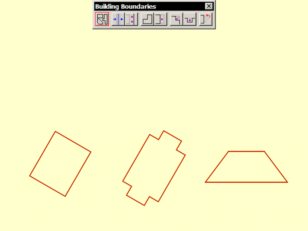
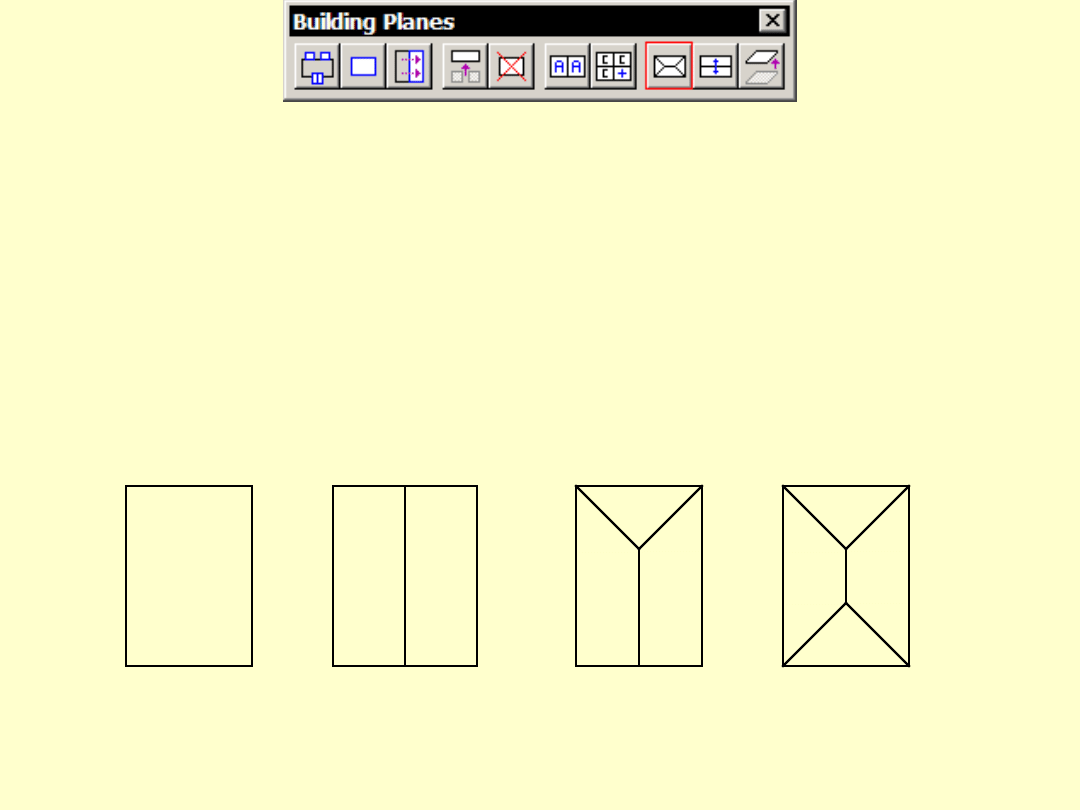
Set Boundary Type
• Set boundary type of a plane
–
Rectangle has four 90 degree corners
–
Rectangular has 4-n corners, all 90 degrees
–
Polygon is a free shape
Rectangle
Rectangular
Polygon
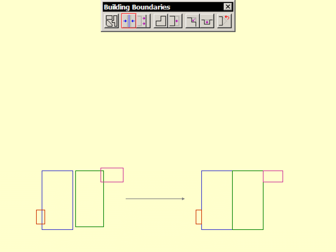
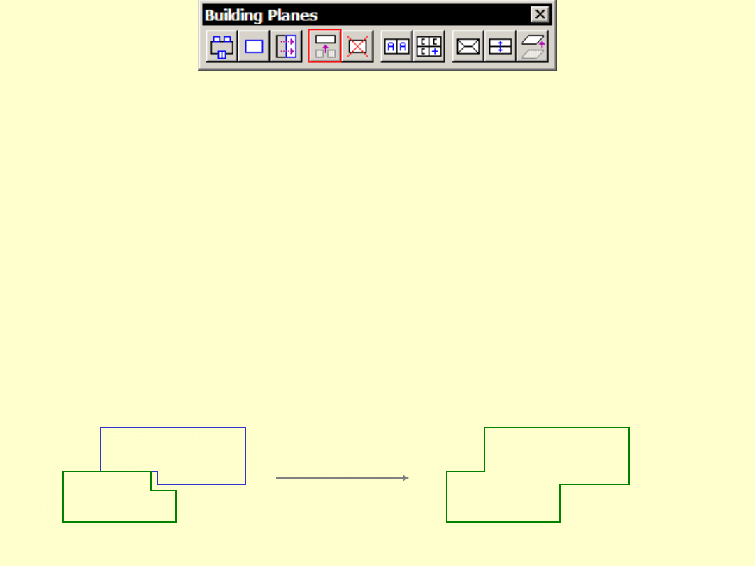
Auto Align Boundaries
• Automatically aligns boundary lines
with
– intersection lines
– each other
– best line position from images (not
implemented)
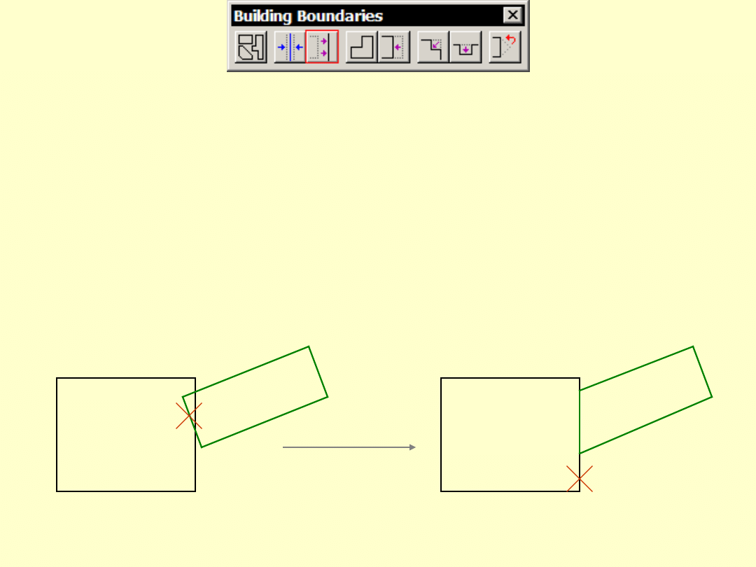
Align Boundary Segment
• Align one boundary segment to another
• Needed when building has multiple
base directions
1
2
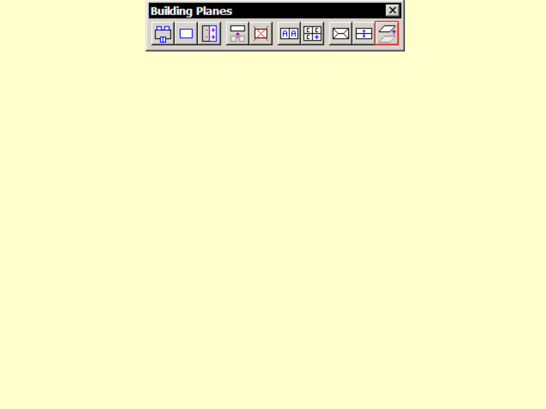
Place Boundary Shape
• Place boundary of a plane manually
• Use when too much editing in
automatic boundary
• Rectangle/rectangular type:
– segment directions constrained by base
direction
• Polygon type:
– Option to align segments close to base
direction
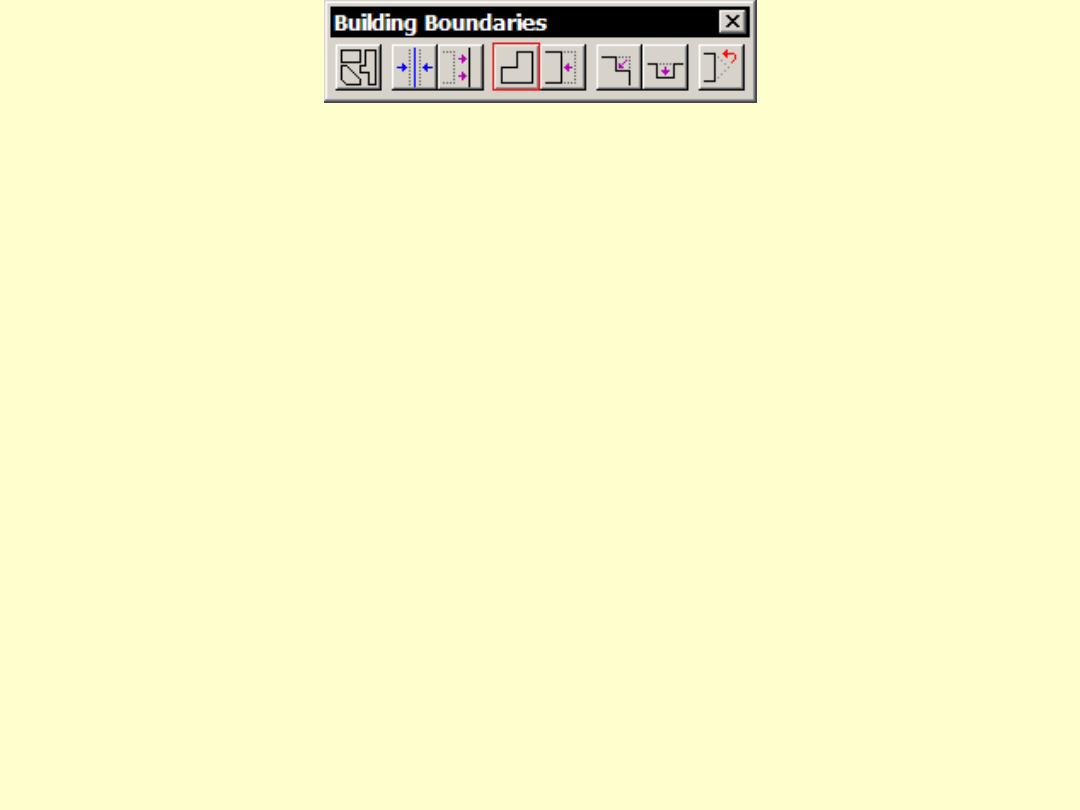
Modify Boundary Shape
• Move a vertex or a segment
• Rectangular boundaries stay rectangular
– linear vertices removed at the end
2
2
1
1
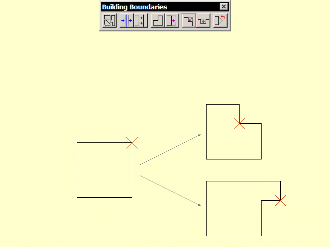
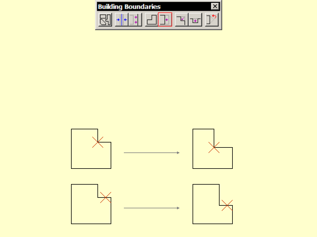
Cut Boundary Corner
• Cut a piece off from a corner
• Add a piece to a corner
1
2
2
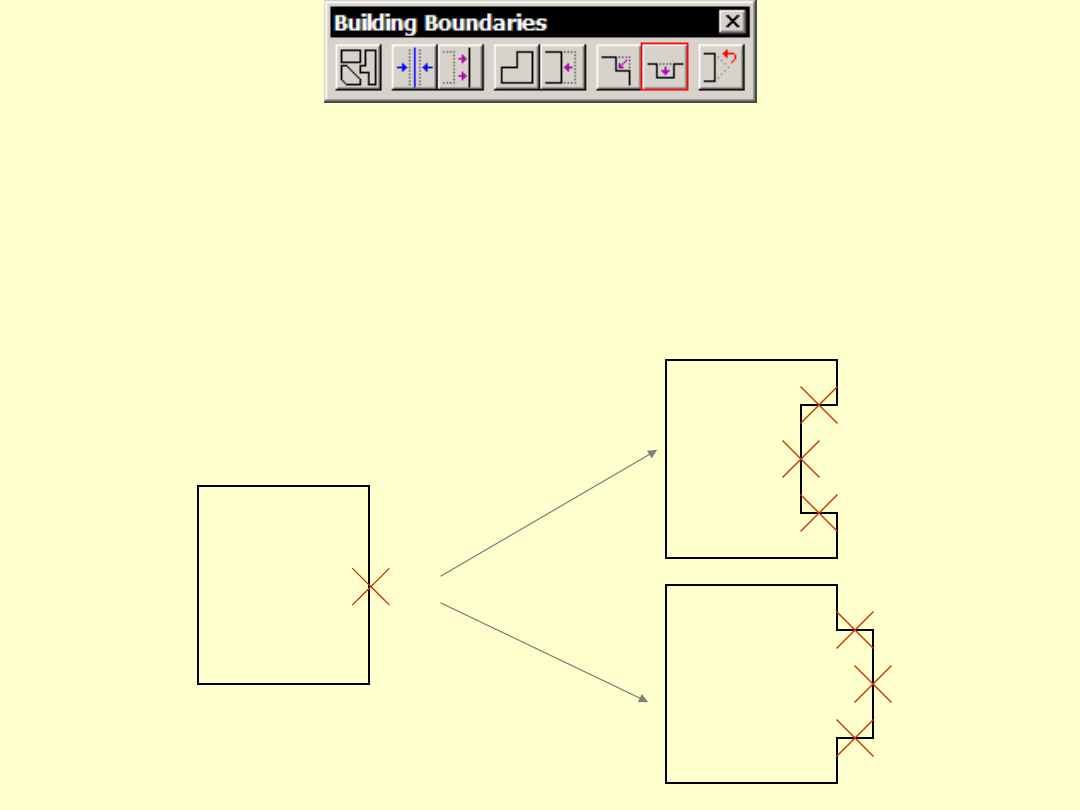
Cut Boundary Segment
• Cut a piece off from a segment
• Add a piece to a segment
1
2
3
4
2
4
3
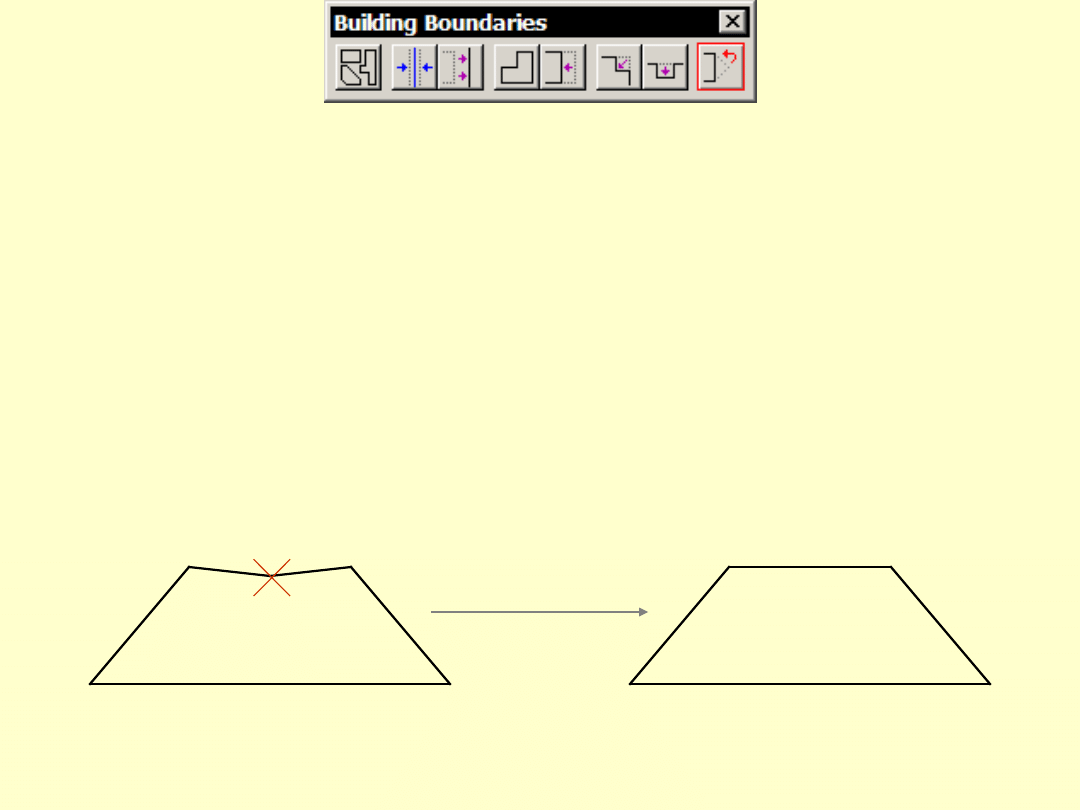
Delete Boundary Vertex
• Removes a vertex from a boundary
• Mainly for polygon type boundaries
1
Document Outline
- Building Vectorization Tools
- Plane list
- Plane direction
- Identifying a plane
- Aerial fill
- Workflow order
- Find Detail Planes
- Add Building Plane
- Mirror Building Plane
- Merge Building Planes
- Delete Building Plane
- Create Direction Group
- Add Plane To Group
- Assign Plane Block
- Assign Plane Symmetry
- Adjust Building Plane
- Set Boundary Type
- Auto Align Boundaries
- Align Boundary Segment
- Place Boundary Shape
- Modify Boundary Shape
- Cut Boundary Corner
- Cut Boundary Segment
- Delete Boundary Vertex
Wyszukiwarka
Podobne podstrony:
Building a Greenhouse
LOGO! in Building Automation
'Building the Pack 3 The Alpha's Only
Building A Wind Machine
Password Recovery Tools, hakerskie
PC TOOLS
GNU Linux Tools Summary
Barrows tackle shop fly tying hooks tools
Debbuging Tools for Windows sposób analizowania błędów
4 2 2 7 Lab Building an Ethernet Crossover?ble
Pumps, tools
35 HSC DLL Tools
Steps in Building a Shed
Arc Hydro Tools Overview v1 0?ta2
64 919 934 New Trends in Thin Coatings for Sheet Metal Forming Tools
konspekt obwód stacyjny z użyciem body building
Modul2, Courseware Development Tools
więcej podobnych podstron