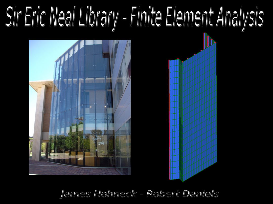
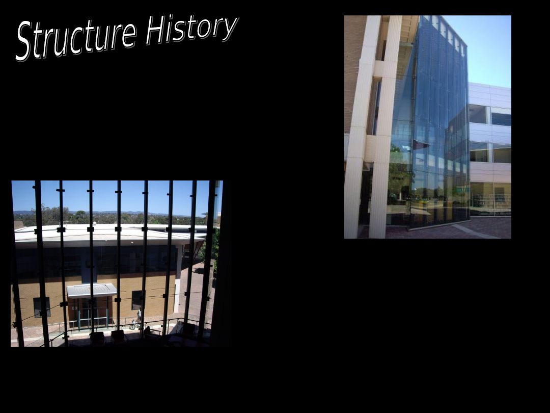
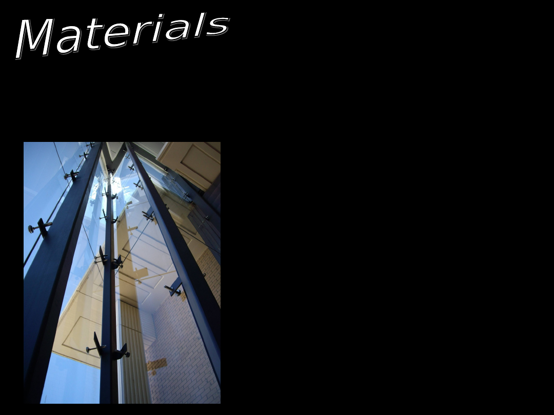
•The Sir Eric Neal Library
extension was
undertaken in early 2005.
• Atrium consists of a mezzanine floor
on level 1 and open for the rest of the
structure
• Extension connected
to existing structure by
a glass atrium
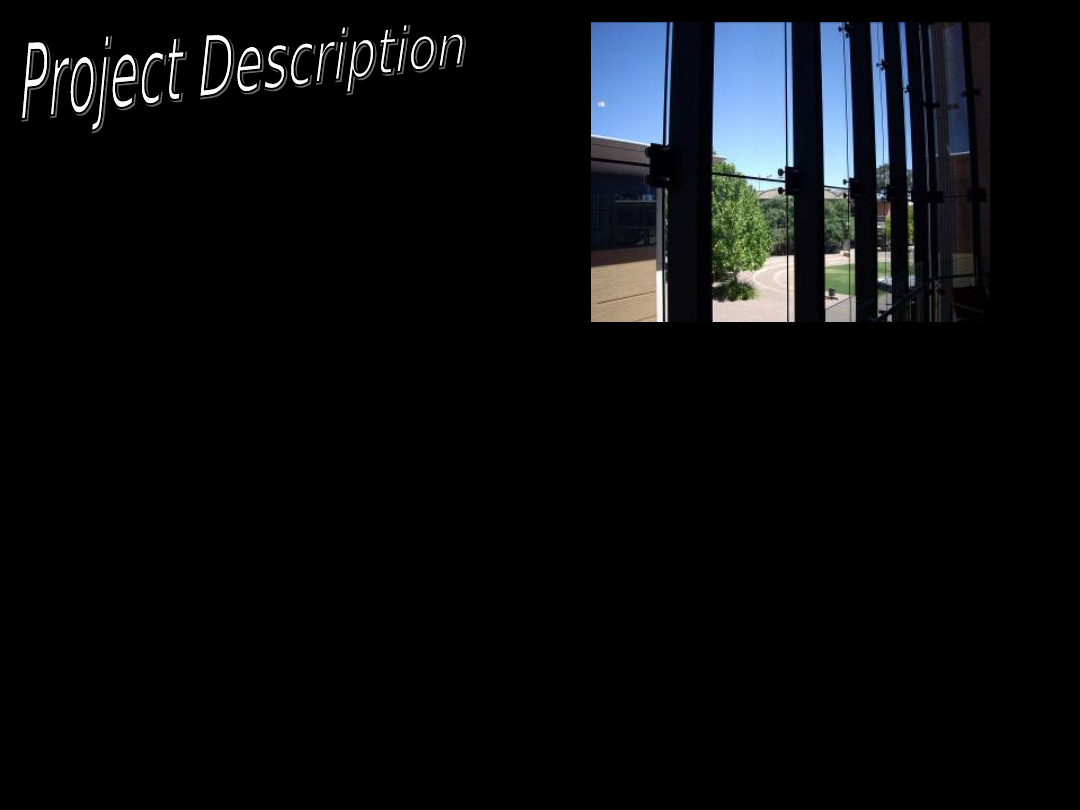
This Finite Element Modelling Project aims
to:
• Model realistically the library glass
wall
• Generate symbolic loading conditions
similar to those applied to the structure
• Analyse the behaviour of the structure
under these loading conditions
•Investigate the limitations the glass
material has on the building design
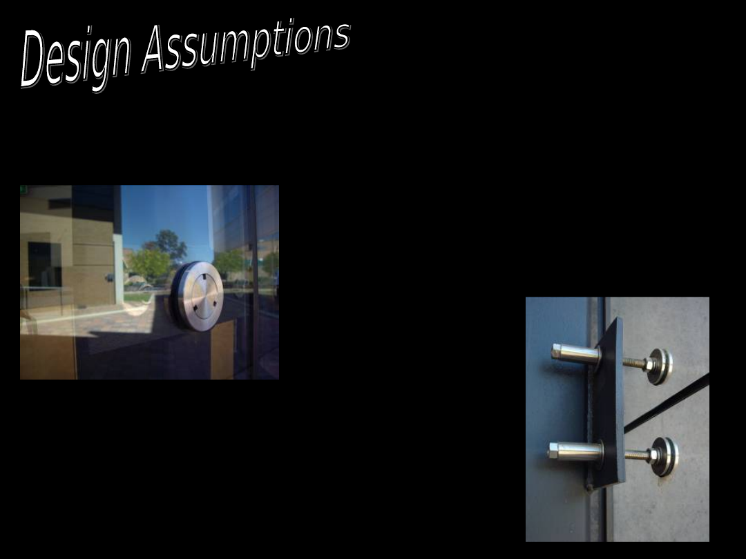
In order to effectively model the
structure the following design
Assumptions were made:
Rubber Clamps modelled as
rigid connectors
Glass plates are assumed to
be connected via small beam
members
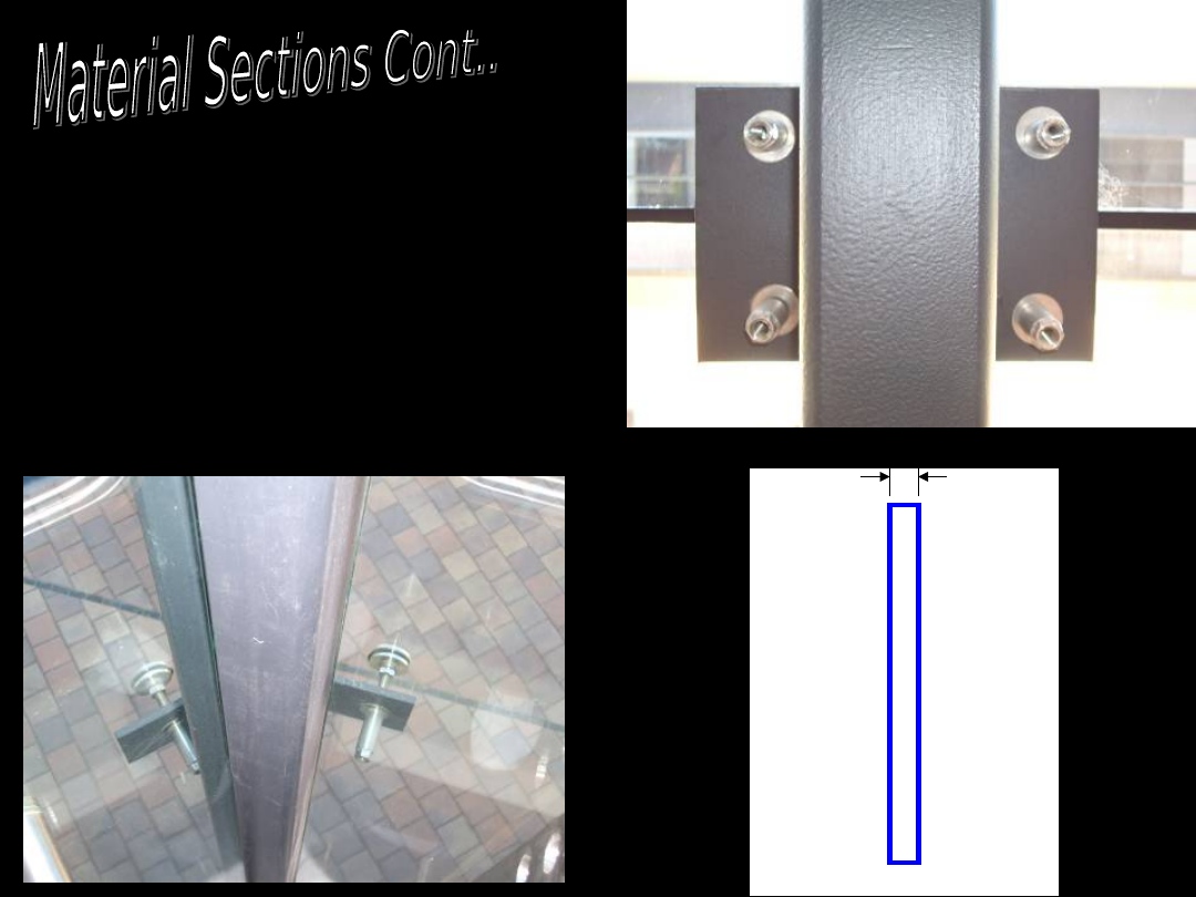
The structure is made from a series of
steel columns and glass plates on the
exterior of the wall.
Small stainless Steel
connectors attach
the glass to the
columns
11 RHS steel
beams
45 Glass Plates
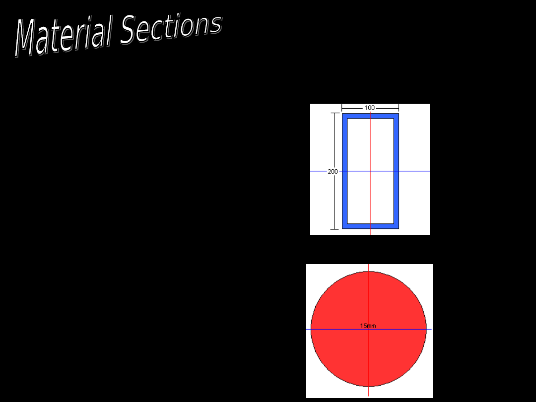
The Materials and their
Properties used in the
model are listed below.
Column
Beam Property
1
Grade 300 Steel
Connectors
Beam Property
2
Grade 310 Stainless
Steel
Glass
Plate/Shell
Element
18mm thick toughened
structural glass
18mm
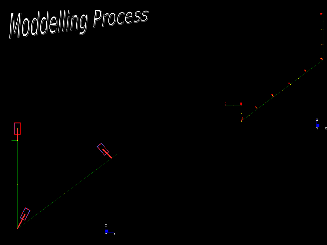
Develop the outlay of the base
nodes
Extrude nodes up by
one plate unit (4m)
Create Plate elements
Create Beam Elements
Change Orientation of
beam principal axis
Generate boundary
conditions
Apply loadings
There were four major
loading conditions that
were investigated in this
model.
Applied Live Loads and Self
Weight Loads
Wind Loading in the XY
plane only
Minor Impact load at the
bottom of the structure
Combination of other three
loads
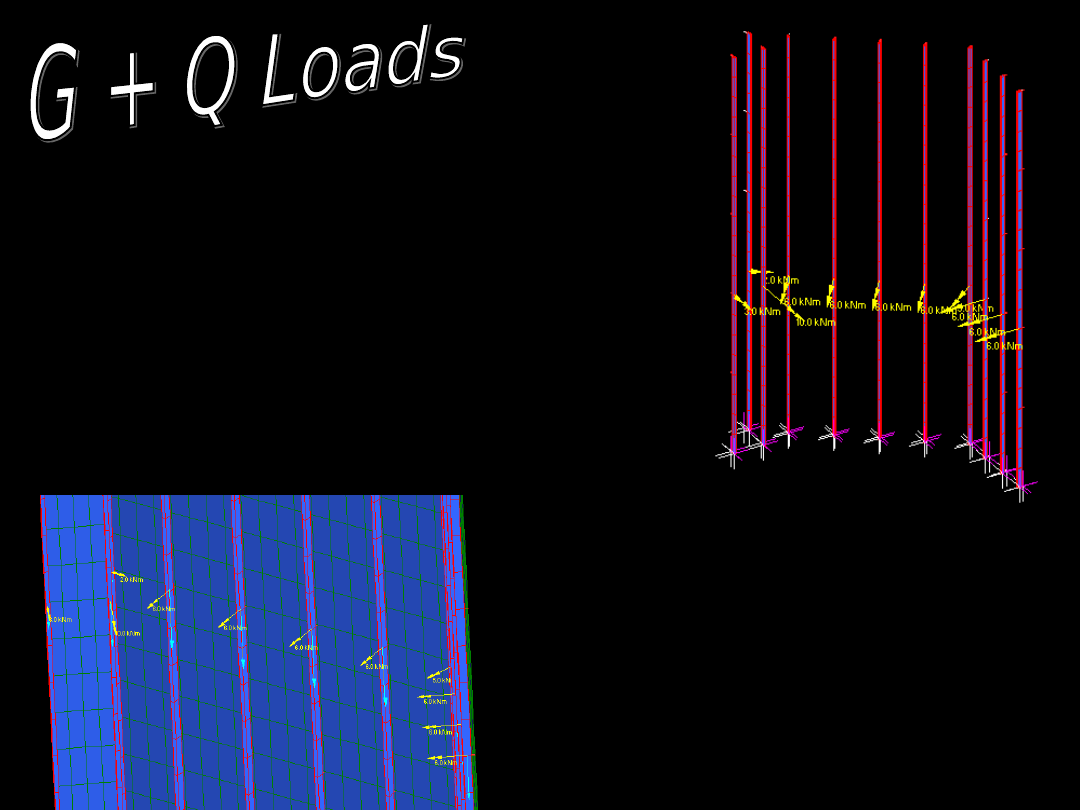
Calculated Moments
Moments are found by AS1170
Applied Axial Load * Moment Arm
Moment Separated into
global directions and then
resultant found
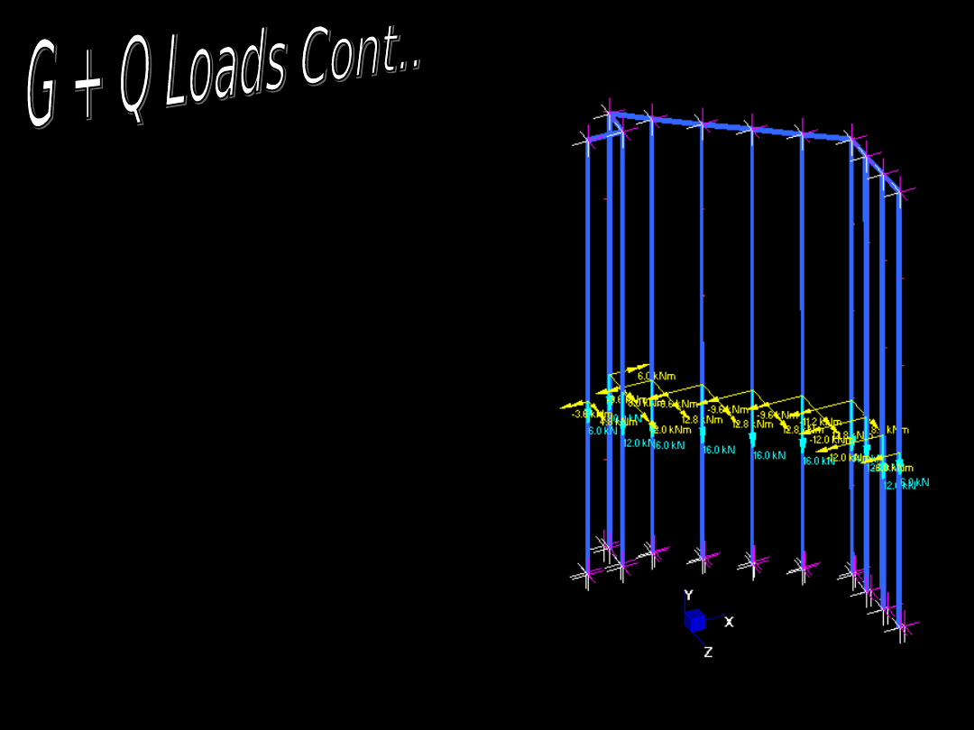
Loads calculated
using AS 1170
Calculated Axial Loads
Assumed Live Load for
reading room with book
storage on level 1
4 kPa
Loads split into effective
moments and axial loads
in the columns
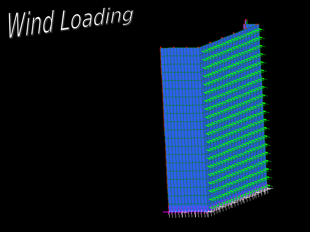
Wind Loading in XY plane
Wind Loads Calculated
using AS1170
Typical wind loading
normal to plates = 0.6kPa
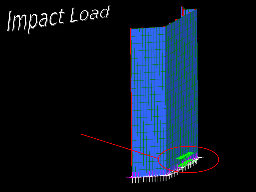
Impact Load
Impact load
representing an
impact from an
object similar
to a vehicle etc
Load = 25kPa spread
across a 4m x 2m
region (on both the
plates and supporting
beams)
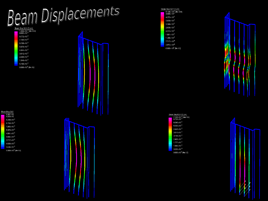
Displacemen
t due to
Combined
Load Case
Displacement due
to G + Q Loads
Displacement due
to Wind Loads
Displacement due
to Impact Loads
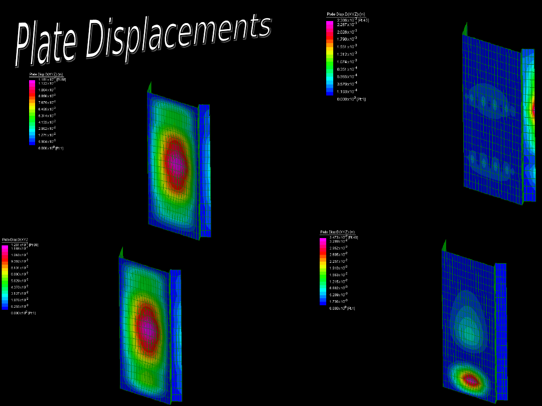
Displacement due
to G + Q Loads
Displacement due
to Wind Loads
Displacement due
to Impact Loads
Displacemen
t due to
Combined
Load Case
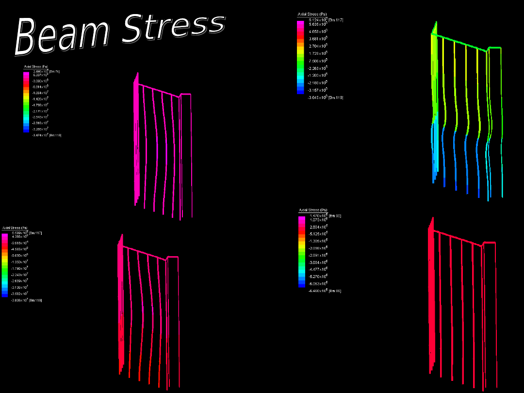
Axial Stress due to
G + Q Loads
Axial Stress due to
Wind Loads
Axial Stress due
to Impact Loads
Axial Stress
due to
Combined
Load Case
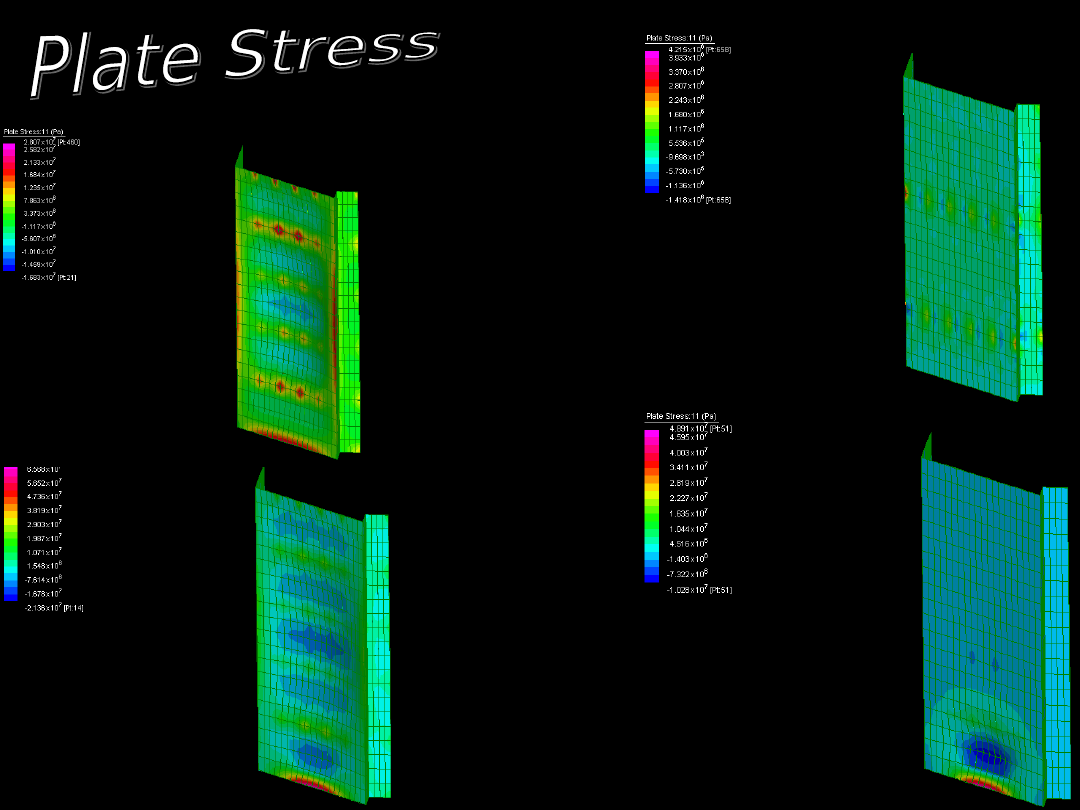
Principal Axis
Stress due to G +
Q Loads
Principal Axis
Stress due to Wind
Loads
Principal axis
stress due to
Impact Loads
Principal
axis stress
due to
Combined
Load Case
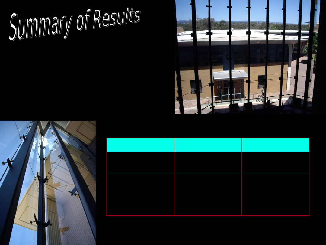
Results
Beam
Plate
Max Stress
-38.06MPa
-71.05MPa
Max
Deflection
108.7mm
125.1mm
The maximum beam
stress values occurred
in member 118 which is
a stainless steel
connector
Viewing Angles made it
difficult to see all of the
nodes etc..
Overcome by:
Two viewing planes
Hiding Selected
objects
Difficult to change the
direction of the principal
axis for each of the
beams
Important to make sure
each of the plates were
connected to the correct
nodes
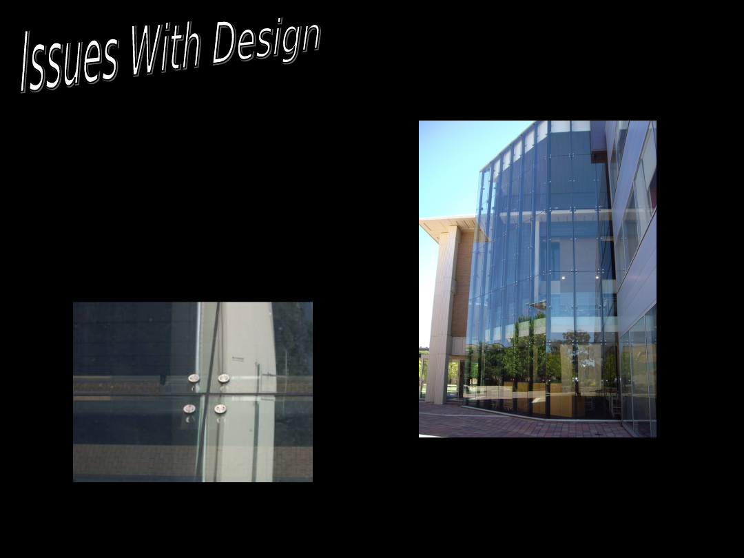
Glass plate deflections
were large. This was due
to the fact that we
modelled using rigid
connections.
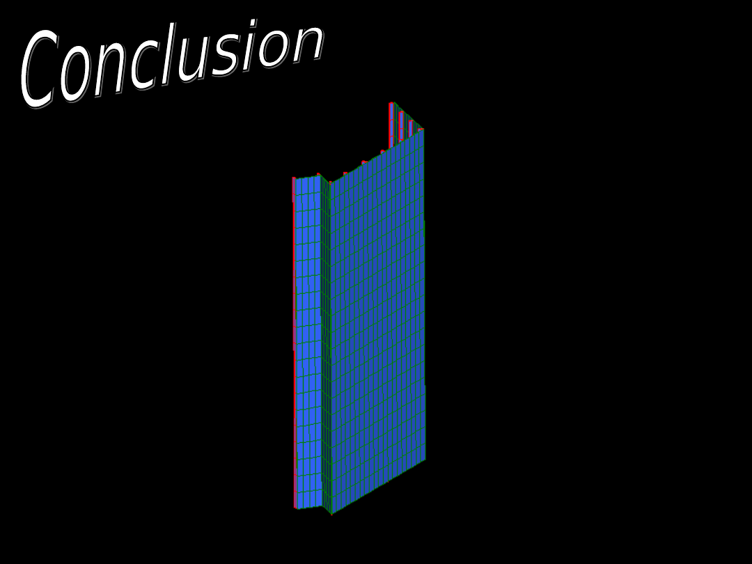
The structure behaved
under the given loading
conditions as expected.
Due to being
modelled as a
rigid connection
the deflections
and stresses in
the glass plates
were larger than
expected.
In real life theses large
deflections would mean
failure of the glass but
much of the stress is
lost through the rubber
connectors.
The angles and
complex connections
in this project made it
a interesting structure
to model.
It is clear to see from the
stresses developed in the
glass plates the limits the
material places on the
structure.
Thankyou for Listening
Document Outline
- Slide 1
- Slide 2
- Slide 3
- Slide 4
- Slide 5
- Slide 6
- Slide 7
- Slide 8
- Slide 9
- Slide 10
- Slide 11
- Slide 12
- Slide 13
- Slide 14
- Slide 15
- Slide 16
- Slide 17
- Slide 18
- Slide 19
- Slide 20
- Slide 21
Wyszukiwarka
Podobne podstrony:
adobe type library 3L4OQ6UISISW Nieznany (2)
proofreading 3 information and library science(1)
Career Skills Library Leadership Skills
Eagle manual library
Libraries
Brentano; Descriptive psychology (International Library of Philosophy)
How to add NED library i
Using the PSpice Library Translator
La Traviata Opera Classics Library
Library
Libraryanalysis
2nd Bibliography Library
Information On Black Libraries
Library
Resource Library
Integral Como Librarse Del Dolor De Cabeza
library
więcej podobnych podstron