
SHORT-CIRCUITS IN
SHORT-CIRCUITS IN
ELECTRICAL POWER
ELECTRICAL POWER
SYSTEMS
SYSTEMS
dr hab. Irena Wasiak, prof.
PŁ
Institute of Electrical Power
Engineering

2 /36
Subject program
Subject program
Lecture
1.
General information on short-circuits, short-
circuit current time course
2.
Principles of calculating asymmetrical short-
circuits
3.
Equipment
impedance
in
symmetrical
components system
4.
Line-to-earth short-circuits in networks with
an ineffective grounded neutral point
Project
1.
Per unit method
2.
Normalized
method
of
short-circuit
calculations

3 /36
Principles of credit
Principles of credit
The lecture is passed based on an exam. The
exam consists of two parts: the first one is
written test (in English). Students who will pass
it will be able to take the second oral part in
Polish.
The project is passed based on individual work
concerning calculating short-circuit quantities
in a selected electrical power system.

4 /36
Literature
Literature
Basic
1. Notes from the lecture
2. Kanicki A.: Wyznaczanie wielkości zwarciowych w
systemie elektroenergetycznym. Available in e-
format.
Additional
1. Kacejko P., Machowski J.: Zwarcia w sieciach
elektroenergetycznych. WNT, Warszawa 1993,
2002
2. Schlabbach J.: Short-circuit currents, IEE, London,
2005

Basic information
Basic information

6 /36
Importance of short-circuit currents
Importance of short-circuit currents
Electrical power systems have to be planned, projected
and constructed in such a way to enable a safe, reliable
and economic supply of loads.
The knowledge about the loading of the equipment is
necessary for the design and determination of the
equipment rating.
Short-circuits during the system operation cannot be
avoided despite careful planning and good maintenance
of the system. Therefore, short-circuit currents have an
important influence on the design and operation of
equipment and the power system a whole.
Equipment and installations must withstand the
expected thermal and electromagnetic effects of short-
circuits. Switchgear and fuses have to switch-off short-
circuit currents in a safe way.

7 /36
Short-circuit classification
Short-circuit classification
Based on the number of connected points –
symmetrical and asymmetrical
Based on fault impedance –
metallic
(direct) i
resistant
(occurring through
impedance, e.g. electrical arc)
Based on the short-circuit location –
far-from-generator
short-circuit and
near-to-
generator
short-circuit
Based on the number of short-circuit places –
single
and multiplace
Based on the location of short circuit places –
internal and
exterior
Based on the moment of short-circuit origin –
simultaneous
and non-simultaneous
Based on the short-circuit duration –
lasting (durable)
and going by

8 /36
Short-circuit statistics
Short-circuit statistics
Frequency of short-circuit occurrence:
Line-to-earth short-circuit –65% av.(from 30% to 97%)
Double line-to-earth short-circuit and line-to-line short-
circuit with earth –20% av. (from 0% to 55%)
Line-to-line short-circuit 10% av. (from 0% to 55%)
Three-phase short-circuit - 5% av. (from 0% to 35%)
Frequency of short-circuit occurrence depends on
nominal voltage of the network and the type of line.
The bigger voltage in the network and the bigger
share of overhead lines the bigger share of line-to-
earth short-circuits.
9 /36
Causes of short
Causes of short
-
-
circuits
circuits
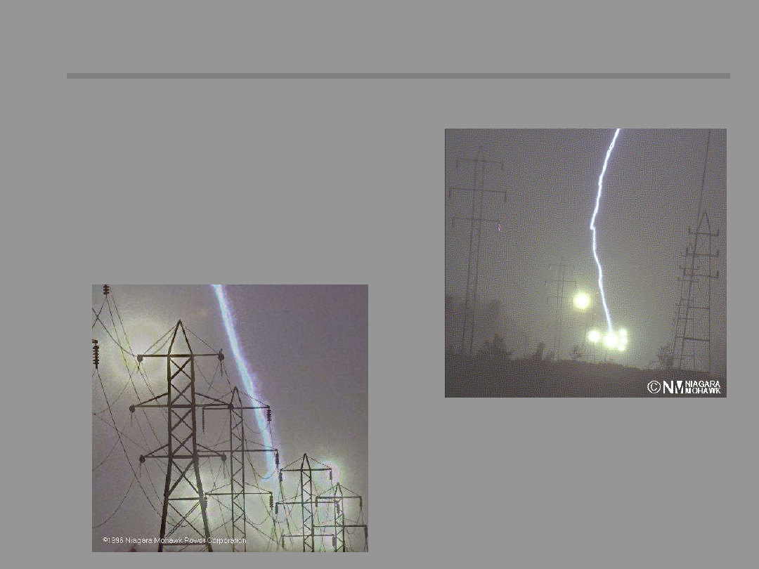
Electrical causes:
Lighting strokes
Switching overvoltages
Switching mistakes
Long-lasting current overloading
10 /36
Causes of short circuits
Causes of short circuits
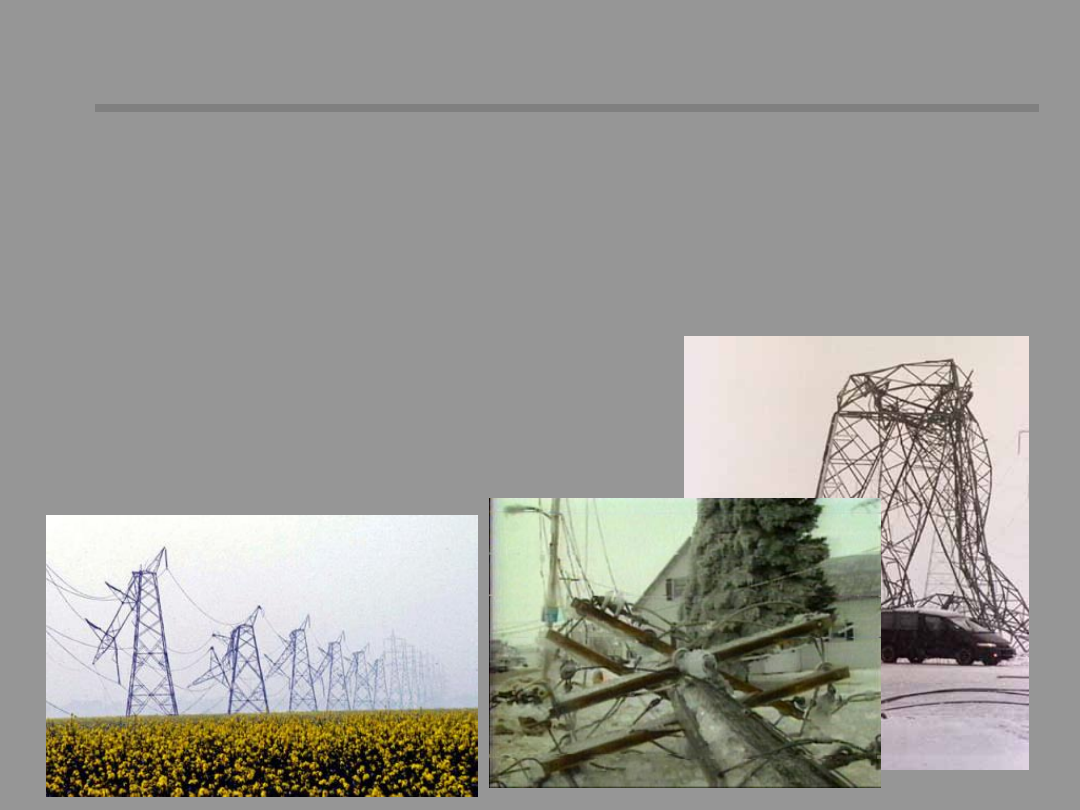
Non-electrical causes:
Humidity and contamination of the insulation of
lines, devices
Ageing of insulation material
Mechanical damages of cables, poles, isolators
Device factory defect
Interference of animals e.g. birds, rodents
Falling over or too high trees
Bringing conductors closer during wind

11 /36
Short-circuit currents effects
Short-circuit currents effects
Thermal effects
A short-circuit causes large current overloading, which are
accompanied by thermal energy proportional to short-
circuit duration. The short-circuit duration depends on the
duration of protection operation.
Dynamic effects
Short-circuit currents cause mechanical forces that affect
current conductors; this may lead to mechanical
destruction
of
equipment.
Short-circuits
stimulate
mechanical oscillations of generators which can cause
problems with power transfer stability.
Electric shock threat
Short-circuit currents flowing through earth can induce
impermissible touch and step voltages.
Voltage dips and overvoltages
The high value of short-circuit current causes the high
voltage of voltage drop in the network, which results in
voltage decreasing in the network nodes. Overvoltages
accompany line-to-earth short-circuits.
Displacement of the voltage neutral-to-eart
12 /36
Short-circuit currents effects
Short-circuit currents effects
Accidental contact of overhead line conductors with a
crane.
Network and system effects
Resulting from switching off the parts of the network being embraced
with fault; economic effects
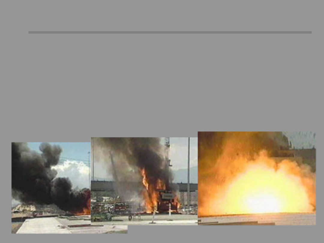
Threats caused by an electric arc
•
Cable melting-down
•
Insulating materials ignition (oil, paper-oil insulation), emission of
smoke and toxic gasses
•
Thermal and ultraviolet radiation of the arc
•
Air heating and blowing-out from the arc space
•
Reducing oxygen in the place where the arc is burning

13 /36
Minimal and maximal short-
Minimal and maximal short-
circuits
circuits
Depending on the purpose of engineering studies
the maximal and minimal short-circuit currents
are calculated.
The maximal current is the main design criteria
for the rating of equipment to withstand the
effects of short-circuit currents, thermal and
electromagnetic.
The minimal short-circuit current is needed for the
design of protection and selection of settings of
protection relays.
The short-circuit current depends on various
parameters: voltage level, impedance of the
network between any generator unit and
the short-circuit location, number of generation
units, fault impedance, etc. Determination of
short-circuit currents requires detailed knowledge
about the elements of electrical power system.
14 /36
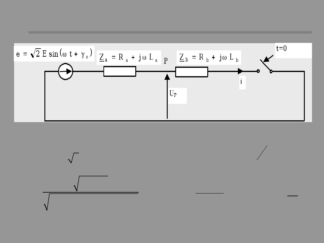
(
)
w +g = +
0
di
2Esin t
Ri L
dt
( )
(
)
(
)
-
=
w +g - j
-
�
� g - j
R
t
L
0
z
0
z
2E
2E
i t
sin t
e
sin
Z
Z
( )
2
2
Z
R
L
=
+ w
w
j =
z
L
arctg
R
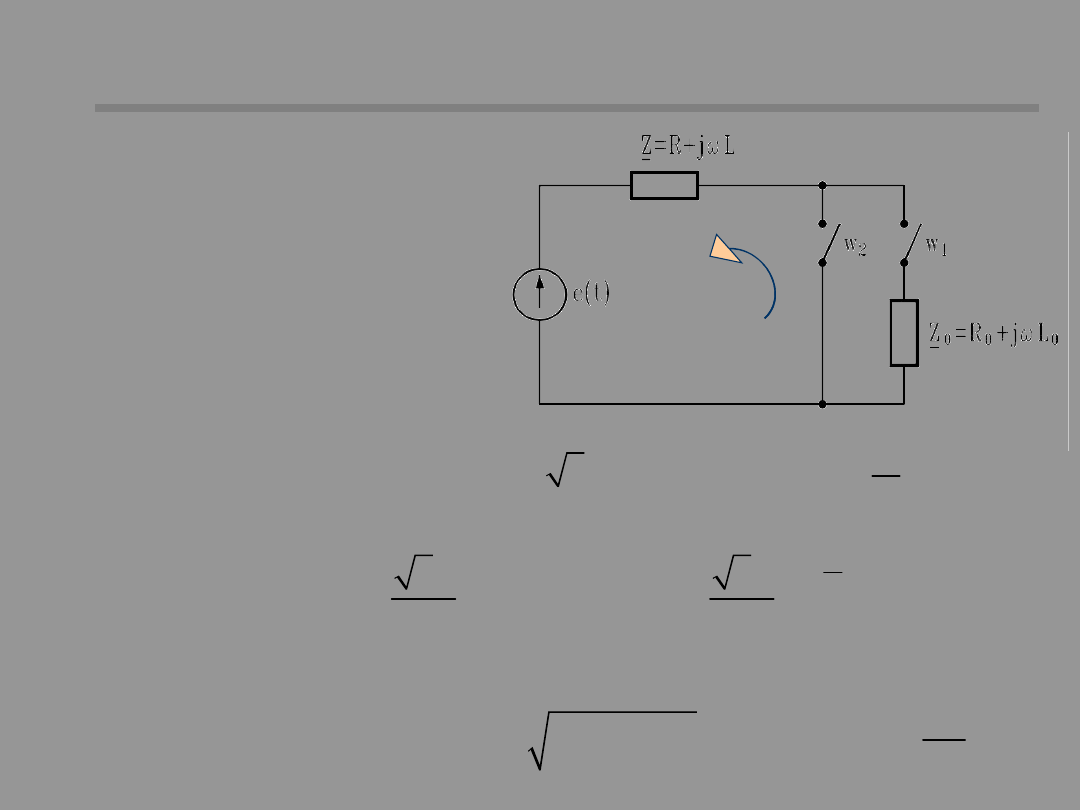
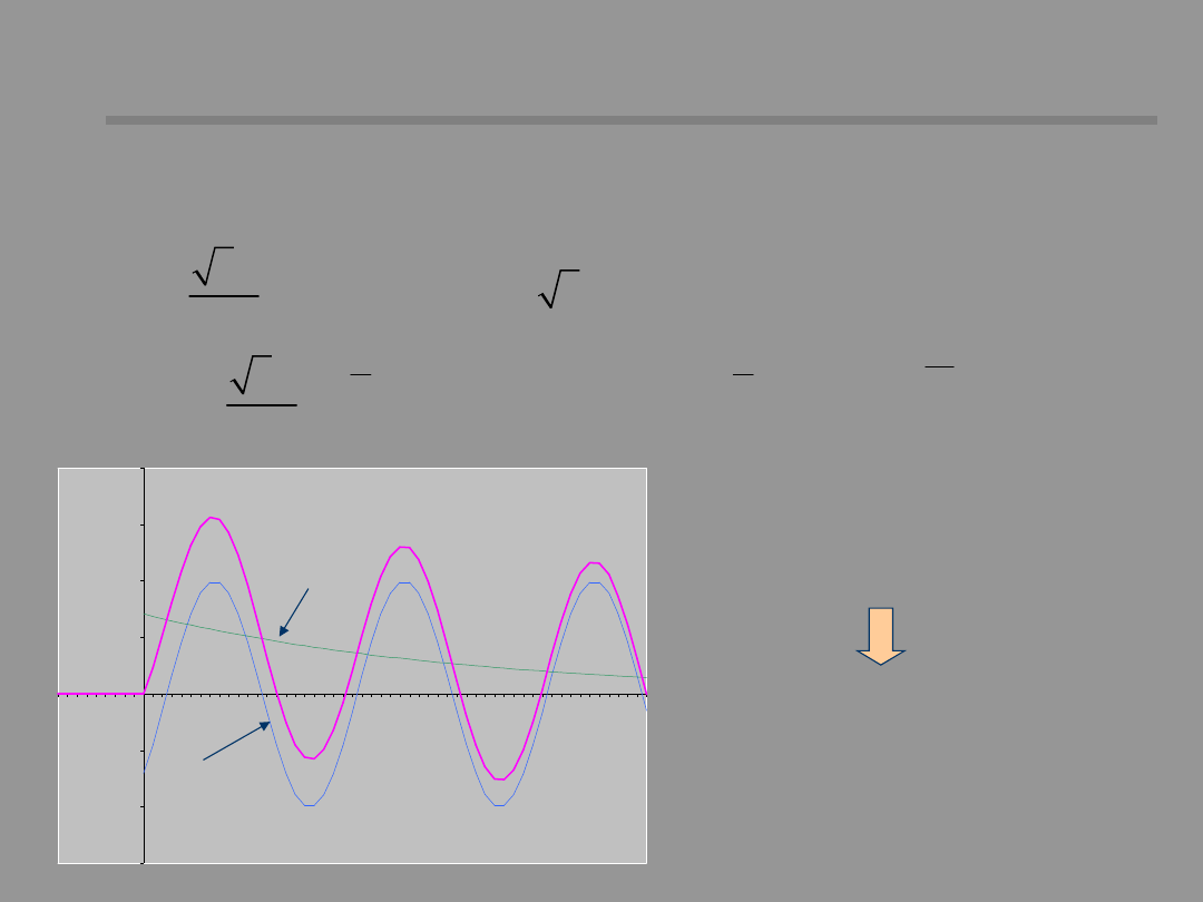
Short-circuit current time course
Short-circuit current time course
Case 1: W1 open –
short-circuit from
unloaded state
Initial condition:
-
=
=
i(t 0 ) 0
E – voltage
R – resistance
L – inductance
Z – impedance
γ
0
– initial voltage phase
angle
z
– short-circuit
impedance angle
15 /36
( )
( )
( )
ok
nok
i t
i
t i
t
=
+
( )
(
)
(
)
=
w +g - j
=
w +g - j
ok
0
z
ok
0
z
2E
i
t
sin t
2I sin t
Z
( )
(
)
-
-
-
=-
�
� g - j
=
�
=
�
a
t
R
R
t
t
T
L
L
nok
0
z
nokm
nokm
2E
i
t
e
sin
i
e
i
e
Z
For the moment
t=0:
i
ok
(0)= - i
nok
(0)
Short-circuit current time course
Short-circuit current time course
-
= = =
i(0) 0 i(t 0 )
-1,5
-1
-0,5
0
0,5
1
1,5
2
i
ok
i
onk
i
ok
– periodic component of short-
circuit current
i
nok
– aperiodic component of short-
circuit current
The principle of current continuity
in RL circuit
16 /36
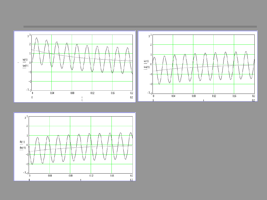
Short-circuit current time course
Short-circuit current time course
Short-circuit current time
course in three phases of
the three-phase system,
when ɣ
0
=0, φ
z
=90°
Phase R
Phase T
Phase S
17 /36
( )
(
)
ob
0
ob
ob
2E
i
t
sin t
Z
=
� w +g - j
(
) (
)
=
+
+ +
2
2
ob
o
o
Z
R R
X X
+
j
=
+
o
ob
o
X X
arctg
R R
( )
( )
( )
( )
-
=
=
=
=
+
ob
ok
nok
i 0 i(0 ) i
0
i
0 i
0
( )
( )
( )
=
=
=- �
-
�
�
�
nok
nokm
ok
ob
i
0 i
i
0 i
0
-1,5
-1
-0,5
0
0,5
1
1,5
2
Short-circuit current time course
Short-circuit current time course
Case 2: W1 closed –
short-circuit from
loaded state
Initial condition:
-
=
=
ob
i(t 0 ) i
18 /36
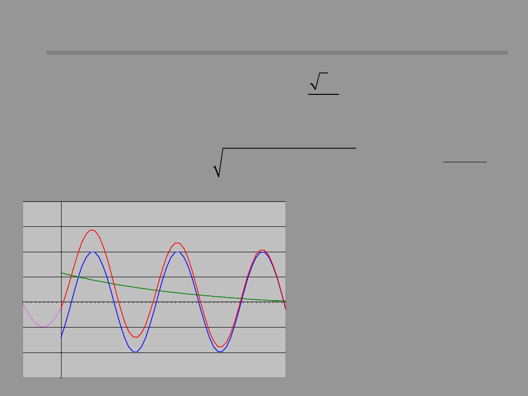
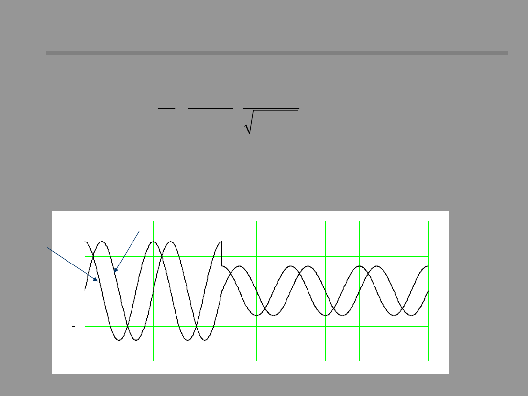
Voltage time course during short-circuit
Voltage time course during short-circuit
(
)
(
)
-
�
�
=
w +g - j +j
-
g - j
�
�
�
�
a
t
T
P
P
0
z
b
0
z
u
2U sin t
K sin
e
T
a
– time constant
Voltage at the P point:
(
) (
)
+
=
+
+
+
2
2
b
b
P
2
2
a
b
a
b
R
X
U
E
R
R
X
X
+
j =
+
a
b
z
a
b
X
X
arctan
R
R
j =
b
b
b
X
arctan
R
19 /36
Voltage time course during short-circuit
Voltage time course during short-circuit
+
=
+
a
b
a
a
b
L
L
T
R
R
�
�
+
=
-
�
�
+
�
�
+
b
a
b
b
2
2
b
a
b
b
b
R
R
R
L
K
L
L
L
R
X
0
0.01
0.02
0.03
0.04
0.05
0.06
0.07
0.08
0.09
0.1
2
1
0
1
2
When R
a
/L
a
=R
b
/L
b
, K=0, and the voltage time course does
not include an aperiodic component. In practice, the K
coefficient has a small value, and the aperiodic component
is omitted.
γ
0
=
90°
γ
0
= 0°
Coefficient K:
20 /36
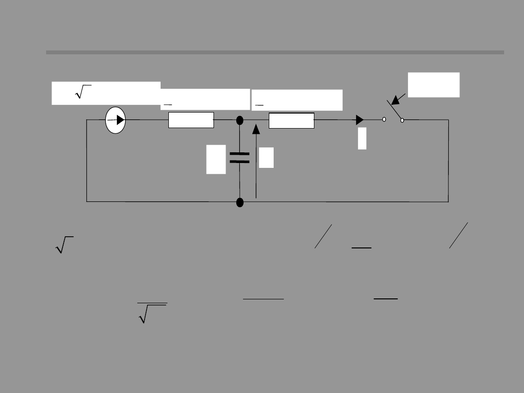
Taking into account the network
Taking into account the network
capacitance
capacitance
(
)
(
)
( )
-
-
�
�
w
�
�
=
w +g - j
-
g - j
-
w
w
�
�
�
�
p
a
t
t
T
T
ok
o
z
o
z
p
p
i
2I
sin t
sin
e
sin
t e
w = p =
p
p
1
2 f
LC
@
+
a b
a
b
L L
L
L
L
=
b
P
b
2L
T
R
f
p
– the frequency of the circuit self-oscillations is from
couple of hundred Hz to couple kHz, the efficient value of
that component does not go over 20% I
ok
.
i
t=0
C
u
)
t
Esin(
2
e
0
a
a
a
L
j
R
Z
b
b
b
L
j
R
Z
21 /36
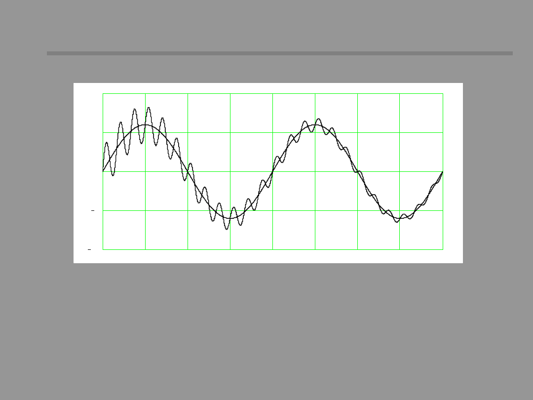
Taking into account the network
Taking into account the network
capacitance
capacitance
0
0.005
0.01
0.015
0.02
0.025
0.03
0.035
0.04
10
5
0
5
10
The short-circuit current time course for the short-
circuit with voltage phase angle of 90°.
22 /36
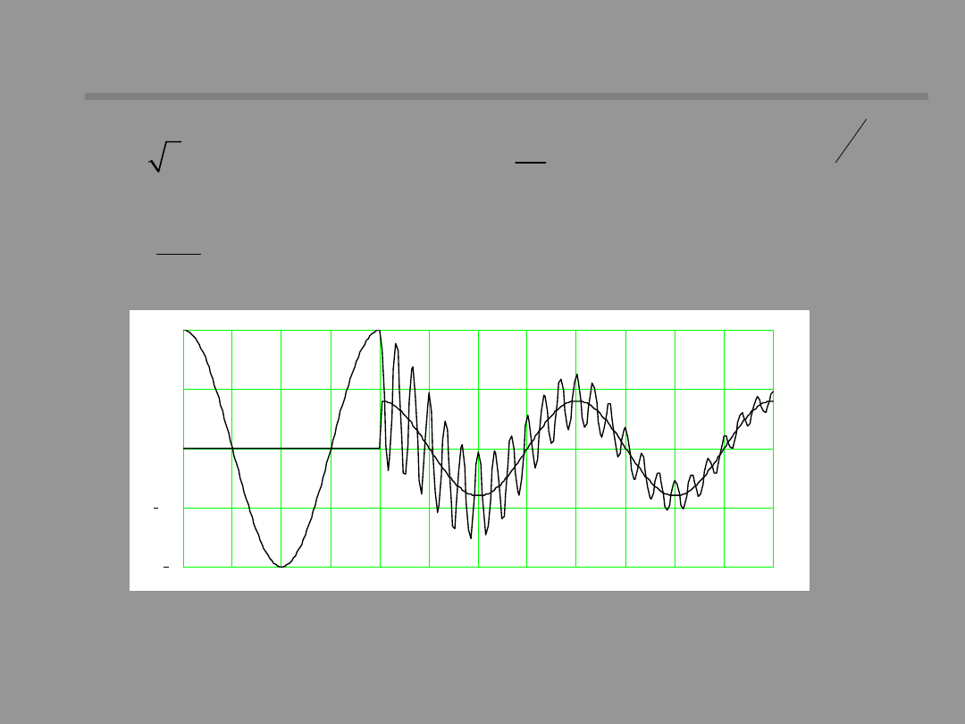
Voltage time course during short-circuit
Voltage time course during short-circuit
(
)
(
) (
)
-
�
�
=
w +g - j +j
+
g - j
w
�
�
�
�
P
t
T
a
P
P
0
z
b
0
z
P
b
L
u
2U sin t
sin
sin
t e
L
=
b
P
b
2L
T
R
0
0.005
0.01
0.015
0.02
0.025
0.03
0.035
0.04
0.045
0.05
0.055
0.06
1
0.5
0
0.5
1
The voltage time course during a short-circuit with the initial
short-circuit angle of 90°.
23 /36
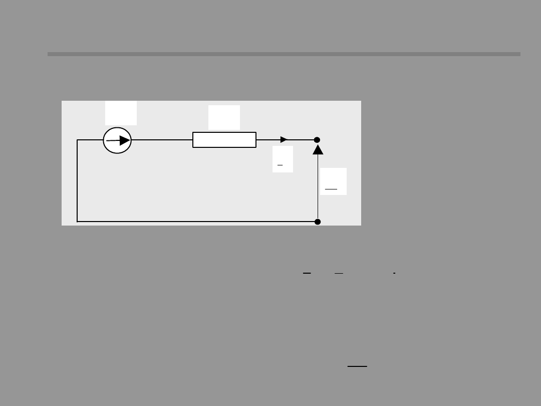
Near-to-generator short circuit
Near-to-generator short circuit
g
U
E
d
X
d
g
I
= +
d
r
ad
X
X X
= +
d
d
g
g
E
U
jX I
=
d
ud
d
E
I
X
Generator is the source of short circuit current.
The equivalent
circuit diagram
of the generator
in steady-state
X
r
– leakage
reactance of stator
windings
X
ad
– mutual
reactance of stator
and rotor
I
ud
– steady-state component of short-
circuit current
d-axis synchronous reactance

24 /36
Consider the sequence of events associated with a
three-phase short-circuit on the unloaded generator.
Before the fault occurs, the field produces an air gap
flux entering the armature and produces time-varying
flux linkages for all mutually coupled circuits
consisting of three phase windings (a, b, c), a field
winding (F) and two damper windings (Q, Q).
A the instant t=0 the fault is applied. This forces flux
linkages to change. By the principle of constant flux
linkages the step change is not possible and all flux
linkages must remained fixed at least for an instant.
(According to magnetic inertia principle the step
change of flux linkages would mean a step change of
energy accumulated in the magnetic field of the
winding.
To counteract sudden flux changes transient dc fluxes
are induced in each winding which maintain flux
linkages constant. These transient fluxes decay to
zero with time constants depending on the resistance
and inductance of each circuit.
Near-to-generator short circuit
Near-to-generator short circuit

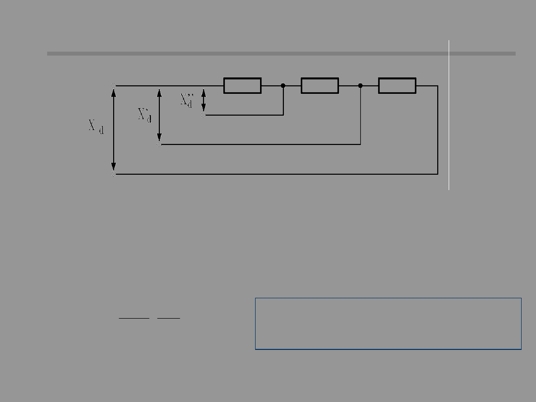
25 /36
The existence of additional fluxes in the generator
circuits changes its magnetic state and a
equivalent reactance which represent the
generator at this state.
At the first moment of the fault transient fluxes
appear in all generator windings; this state is
called subtransient and the generator is
represented by so called subtransient reactance
X”
d
. After the decaying of transient dc flux in rotor
damper windings (time period of (
0,01-0,05
s) the
generator passes on to the transient state and is
represented by transient reactance. Then, when
the flux at the field winding decays (
0,6-1)
s the
generator reaches steady state and the
representing reactance is X
d
.
Near-to-generator short circuit
Near-to-generator short circuit
26 /36
In short-circuit calculations
we will analyze the
currents at the initial moment of the short-
circuit. This is a subtransient state for
generator, so it can be represented by the
reactance X
d
”
Generator equivalent circuit
Generator equivalent circuit
diagram
diagram
"
2
d%
1n
g
n
X
U
X
100 S
=
�
U
n
– rated generator voltage [kV]
S
n
-
rated generator power [MVA ]
[ ]
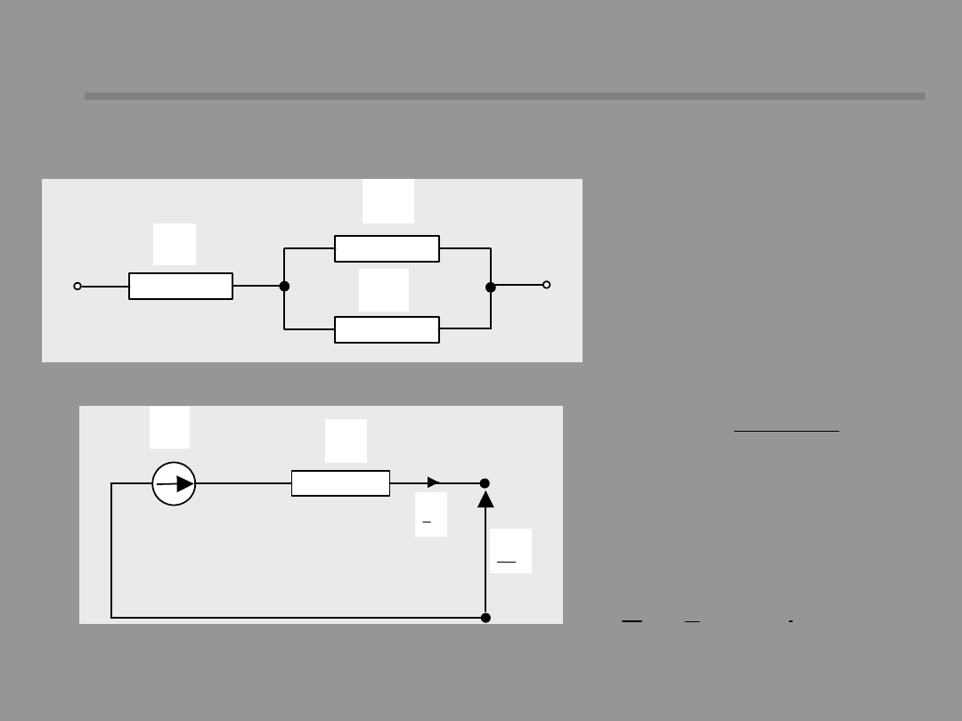
27 /36
r
X
ad
X
rf
X
�= +
+
rf ad
d
r
rf
ad
X X
X
X
X
X
g
U
d
E
g
I
'
d
X
Near-to-generator short circuit
Near-to-generator short circuit
Transient state
X
rf
– leakage
reactance of the field
winding
X
r
– leakage
reactance of the
armature winding
�
�
= +
d
d
g
g
E
U
jX I
Transient
electromagnetic force
(EMF)

28 /36
'
d
d
d0
d
X
T
T
X
� �
=
'
d
Z
d
d0
d
Z
X
X
T
T
X
X
+
� �
=
+
-
�
�
D =
-
�
�
�
�
�
�
'
d
t
'
T
'
d
d
d
'
d
d
E
E
I
e
X
X
Near-to-generator short circuit
Near-to-generator short circuit
An additional transient flux in the magnetizing
winding decays with the time-constant T’
d
.
T’
d0
– time-constant with
the armature circuits
open
(5-12) s
Typically, T’
d
is about ¼ that of T’
d0.
If the short-circuit occurs behind an outer
reactance:
An additional direct flux in the field
winding causes a positive sequence
additional current component in the
armature
29 /36
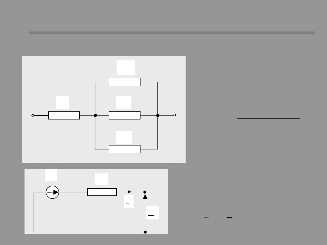
Near-to-generator short circuit
Near-to-generator short circuit
Subtransient state
r
X
rf
X
rD
X
ad
X
�
�= +
+
+
d
r
rD
rf
ad
1
X
X
1
1
1
X
X
X
X
rDf
– leakage
reactance of the
rotor dumper
winding
g
U
d
E
g
I
d
X
d q
d
q
E
U
jX I
�
�
�
= +
Subtransient
electromagnetic
force (EMF)

30 /36
Near-to-generator short circuit
Near-to-generator short circuit
An additional direct flux in the damper winding decays
with time-constant T’
d
.
d
d
d0
d
X
T
T
X
�
�
�
� �
�
=
�
�
�+
�
� �
�
=
�+
d
Z
d
d0
d
Z
X
X
T
T
X
X
If the short-circuit occurs behind an outer reactance:
T”
d0
– time-constant with the armature
circuits open (0,02-0,2) s
-
�
�
�
�
�
� �
�
�
D =
-
�
�
�
� �
�
�
d
t
T
d
d
d
d
d
E
E
I
e
X
X
An additional direct flux in the damper
winding causes a positive sequence
additional current component in the
armature
Typical value of T”
d
is 2
cycles
31 /36
Near-to-generator short circuit
Near-to-generator short circuit
Alternating short-circuit current in d-axis is the sum of steady and transient
components:
�
� �
=D +D +
okd
d
d ud
I
I
I
I
-
-
�
�
�
�
�
�
�
�
� �
�
=
-
+
-
+
�
�
�
�
�
� �
�
�
�
�
�
d
d
t
t
T
T
d
d
d
d
d
okd
d
d
d
d
d
E
E
E
E
E
I
e
e
X
X
X
X
X
-
�
�
�
�
�
�
=
-
+
�
�
�
�
�
�
�
�
q
t
T
q
q
q
okq
q
q
q
E
E
E
I
e
X
X
X
Alternating short-circuit current in g-axis does not include
the field component (no field winding in the q-axis)
32 /36
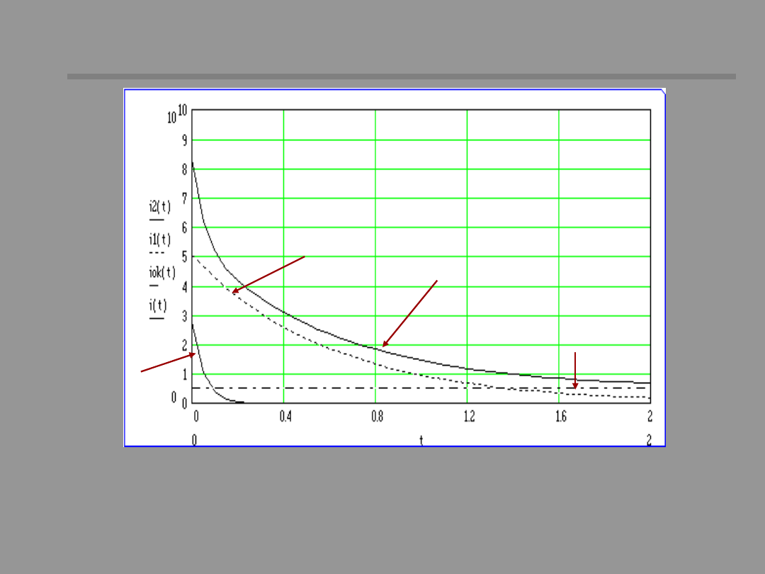
Near-to-generator short circuit
Near-to-generator short circuit
The time course of rms values of short-circuit ac current components.
Short-circuit at the terminals of unloaded generator.
Subtransie
nt
component
Transient
compone
nt
AC current
Steady
state
component
33 /36
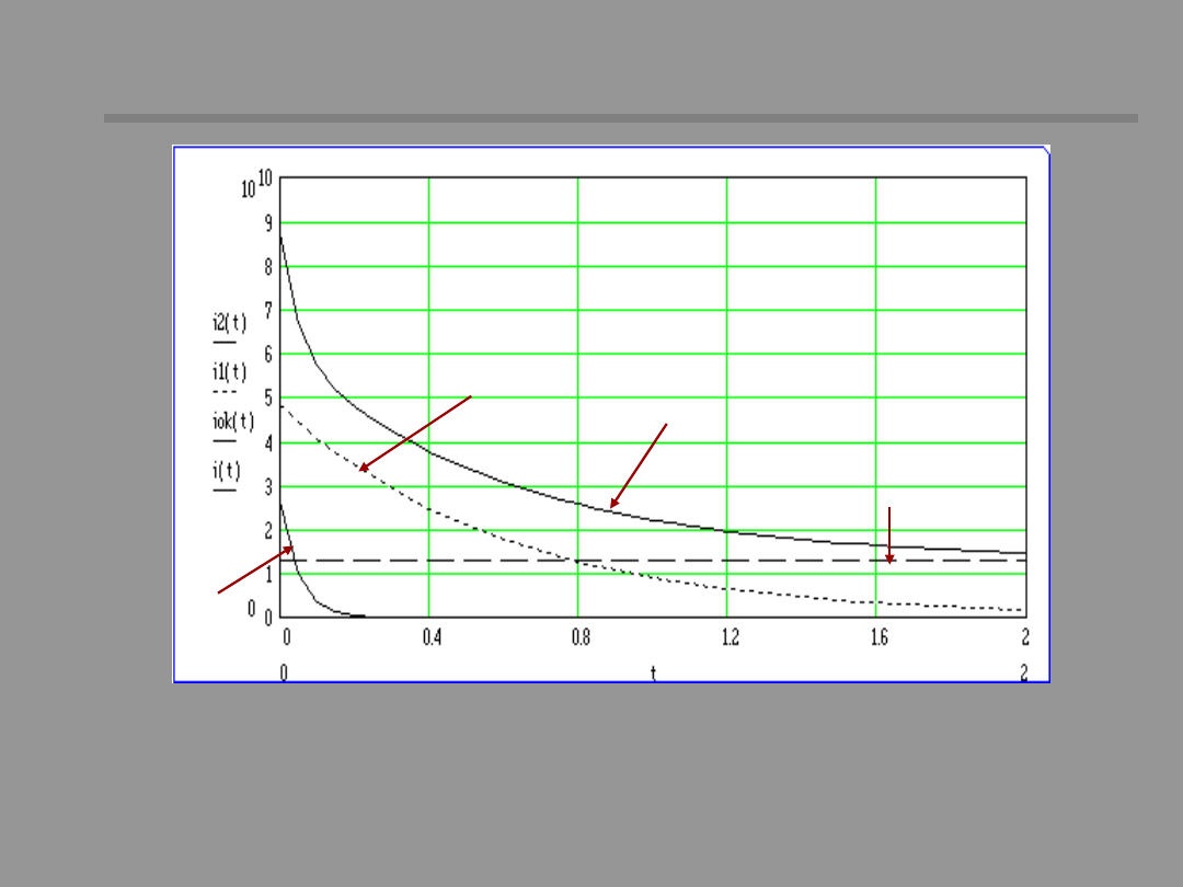
Near-to-generator short circuit
Near-to-generator short circuit
The time course of rms values of short-circuit ac current components.
Short-circuit at the terminals of generator rating loaded.
Subtransie
nt
component
Transient
compone
nt
AC current
Steady
state
component
34 /36
Near-to-generator short circuit
Near-to-generator short circuit
Alternating-current component of short-circuit current for t=0 is
called the initial current:
(
)
(
)
(
)
� �
�
�
� �
�
�
�
�
=
=
= �
=
�+
=
=
+� �
� �
�
� �
�
� �
�
�
�
�
� � � �
2
2
2
2
q
d
p
ok
okd
okq
d
q
E
E
I
I
t 0s
I
t 0s
I
t 0s
X
X
The forward wave moves at twice synchronous
speed with respect to the armature and
induces a second harmonic current in the
armature circuit; amplitude (5-10)% I
n
.
+
-
In the armature windings an aperiodic components appear as the result of
direct transient flux occurrence (by the principle of constant stator flux
linkage). It decays with the time-constant T
a
= (0,3-5) s. It induces
additional ac currents in the field winding, decaying to zero with time-
constant T
a
. Such an ac current produces a pulsating flux which is
stationary with respect to waves, one is going forward and one backward.
The backward is such as to oppose the stationary armature field.
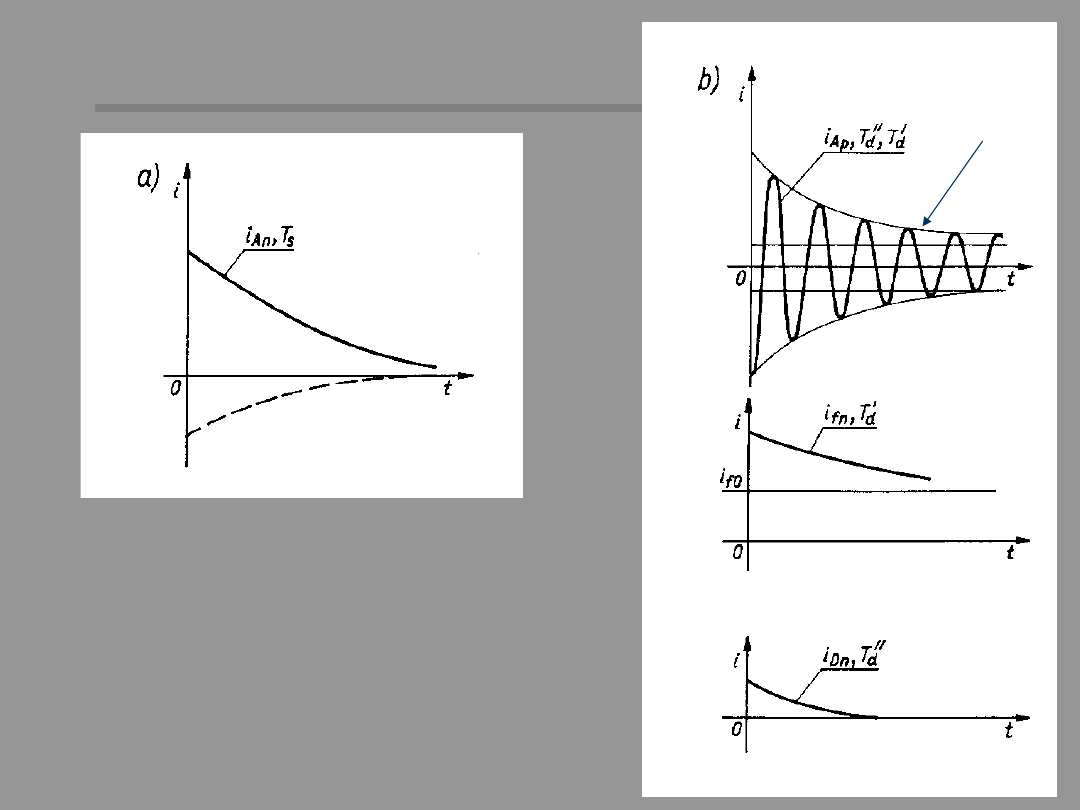
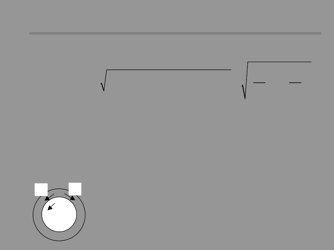
35 /36
a) Armature dc current
component
b) Armature ac current
component and transient
dc currents in rotor
windings
Near-to-generator short circuit
Near-to-generator short circuit
Transient
current in
the field
winding
Transient
current
in
damper
winding
AC
componen
t envelope
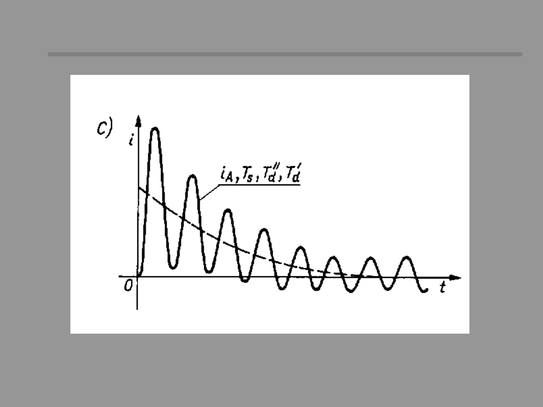
36 /36
The time course of the total stator current
Near-to-generator short circuit
Near-to-generator short circuit
Document Outline
- Slide 1
- Slide 2
- Slide 3
- Slide 4
- Slide 5
- Slide 6
- Slide 7
- Slide 8
- Slide 9
- Slide 10
- Slide 11
- Slide 12
- Slide 13
- Slide 14
- Slide 15
- Slide 16
- Slide 17
- Slide 18
- Slide 19
- Slide 20
- Slide 21
- Slide 22
- Slide 23
- Slide 24
- Slide 25
- Slide 26
- Slide 27
- Slide 28
- Slide 29
- Slide 30
- Slide 31
- Slide 32
- Slide 33
- Slide 34
- Slide 35
- Slide 36
Wyszukiwarka
Podobne podstrony:
p 43 ZASADY PROJEKTOWANIA I KSZTAŁTOWANIA FUNDAMENTÓW POD MASZYNY
Rodzaje fundamentów
RF04 T07 Analiza fundamentalna
21 Fundamnety przyklady z praktyki
Fundamenty bezpośrednie
55 06 TOB Fundametowanie II
Mathcad fundamenty ramowe
A2 Fundamenty
fundamentowanie1
FUNDAMENTOWANIE 2 b materia
Japońskie techniki inwestycyjne, Analiza techniczna i fundamentalna, Analiza techniczna i fundamenta
Fundamentalizm islamski, Bezpieczeństwo Narodowe, Międzynarodowe stosunki polityczne
Próbne Obciążenie Gruntu, BUDOWNICTWO, Fundamenty, Fundamentowanie i Mechanika Gruntów, fund, fundam
fundamenty , Resources, Budownictwo, Fundamentowanie, Projekt, Fundamentowanie, Fundamentowanie-1
rodzaje pokus, medytacje do fundamentu
warunki modlitwy medyt, medytacje do fundamentu
Analiza fundamentalna Wybieranie i odrzucanie spółek Analiza fundamentalna
więcej podobnych podstron