

Direct3D 11 Tessellation
Direct3D 11 Tessellation
Speaker: Kevin Gee
Research: Charles Loop / Scott Schafer
Slides: Shanon Drone, Matt Lee, Michael
Oneppo

Design Background
Design Background
Programmable pipeline can target any
surface approach.
One primary scenario facilitates
subdivision surfaces as a primitive
type.
Charles Loop and Scott Schaefer
provided a reference approximation to
Catmull-Clark.
Converts Sub-D surface into Bezier
patches.
Other approaches are possible too.

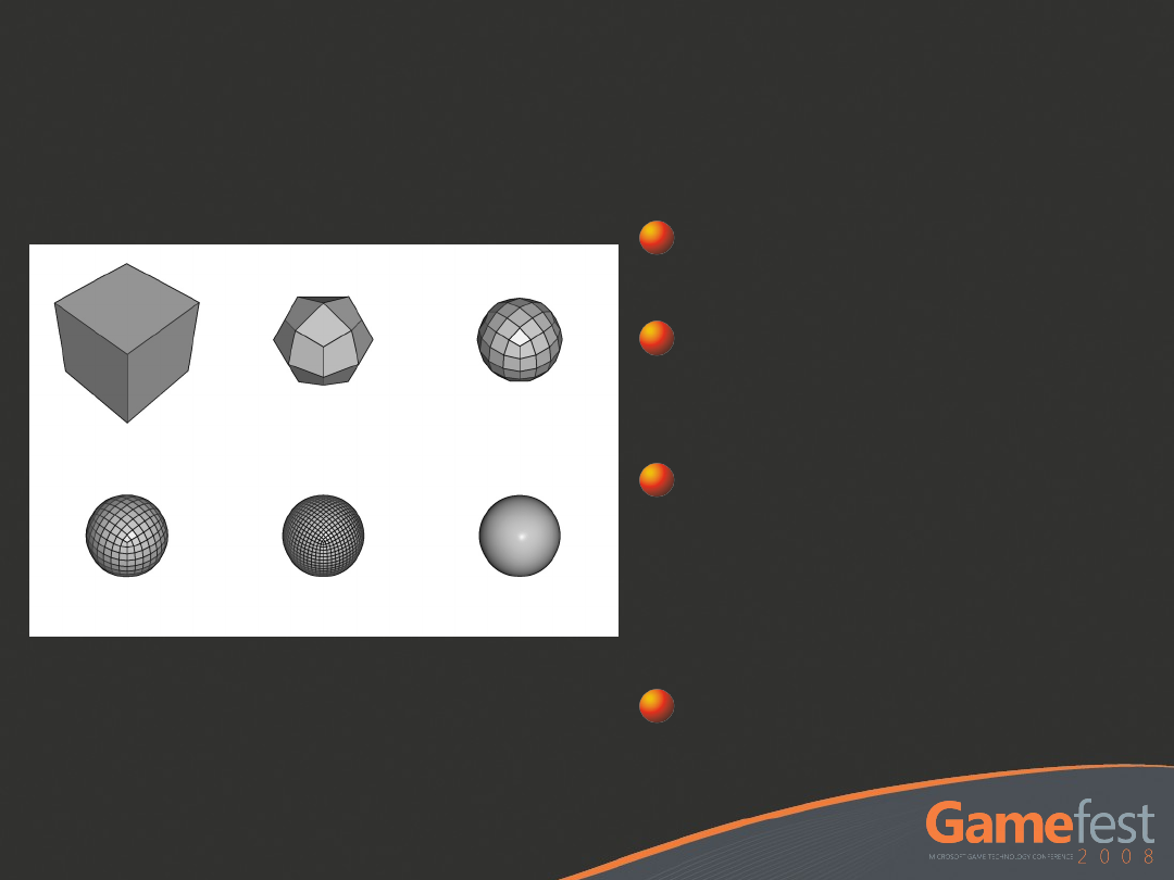
Why Tessellate?
Why Tessellate?
Many reasons including
Reduced asset memory size
More morph targets
Cheap / free LODs
Reduced asset creation time
Improved pixel shader utilization
Reduced GPU skinning costs
Run faster simulations
Move Sub-D costs to GPU
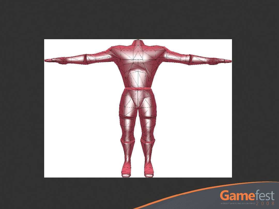
Pre-Tesselated Mesh: ~5500 kb
Asset Size: Comparison
Asset Size: Comparison
Sub-D Mesh: ~130 kb
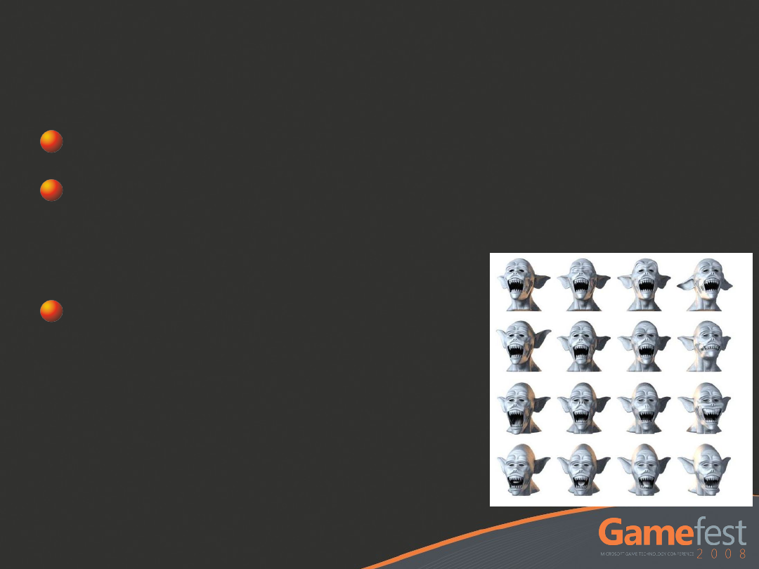
Morph Targets
Morph Targets
Huge potential memory / size wins
Morph targets in Sub-D take up less
space than fully-tessellated \ sparse
morph targets
Enable richer animations
for the same memory cost

Level of Detail
Level of Detail
Continuous LOD becomes possible.
Reduces content creation time
Cheaper than building & testing explicit
LODs
Improves pixel shader quad
utilization

Faster Simulation
Faster Simulation
Skin at the control mesh level
Saves skinning costs
Cloth in Sub-D
Reduces the resolution of the simulation
Keeps a smooth surface for rendering
The more complex the simulation, the
bigger the savings
Compute surface constraints at a
lower frequency
Limit high-frequency positions to avoid
penetrations

DIRECT3D 11
DIRECT3D 11
PIPELINE OVERVIEW
PIPELINE OVERVIEW
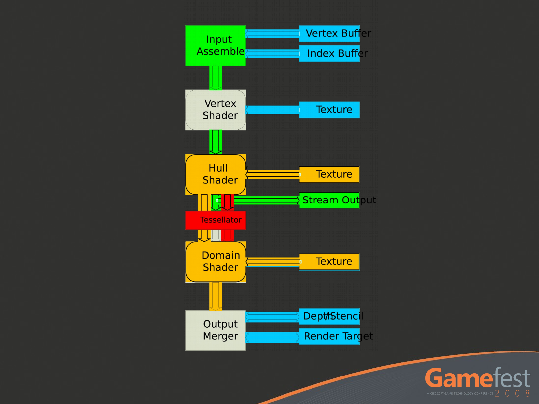

New Primitives
New Primitives

Hull Shader
Hull Shader
Operates per input primitive
E.g. patch
Computes control point transforms
E.g. Basis Change
Computes tessellation factors per
edge of generated patches

Hull Shader Syntax
Hull Shader Syntax
[patchsize(12)]
[patchconstantfunc(
MyPatchConstantFunc
)]
MyOutPoint
main(uint Id : SV_ControlPointID,
InputPatch<
MyInPoint
, 12> InPts)
{
MyOutPoint
result;
…
result =
TransformControlPoint
( InPts[Id] );
return result;
}

Tessellator
Tessellator
Inputs
Takes in “Tessellation Factors” provided
by the Hull shader
Tess factors per-side in the range of
[2.0..64.0]
Outputs
UV or UVW domain points
Connectivity of those points (tris, lines)
No adjacency information
Many possible partitioning schemes

Tessellation Scheme
demo

Domain Shader
Domain Shader
Operates on each point generated by
the tessellator
Gets ALL control points as input
Control points and patch constant data
are passed directly to the domain
shader
Evaluate primitive surface to
compute position of points
Convert from U,V space into positions,
tangents

Domain Shader Syntax
Domain Shader Syntax
void main( out
MyDSOutput
result,
float2 myInputUV : SV_DomainPoint,
MyDSInput
DSInputs,
OutputPatch<
MyOutPoint
, 12> ControlPts,
MyTessFactors
tessFactors )
{
…
result.Position =
EvaluateSurfaceUV
( ControlPoints,
myInputUV );
}

APPLYING SUBDIVISION
APPLYING SUBDIVISION
SURFACES TO THE PIPE
SURFACES TO THE PIPE

What Are Subdivision
What Are Subdivision
Surfaces?
Surfaces?
Surfaces defined by iterative
refinement
Many different techniques
Catmull-Clark (1978)
Doo-Sabin (1978)
Loop (1987)
Techniques differ primarily in edge
cases and fixing trouble spots in
previous techniques
Catmull-Clark Subdivision
Catmull-Clark Subdivision
Start with a
quad mesh
Faces and edges
are split in the
center
Vertices are
averaged with
their
surrounding
neighbors
Infinite iteration
results in the
“limit surface”

Why Catmull-Clark?
Why Catmull-Clark?
Broad support from industry and
modeling packages
Parametric evaluation introduced in
1998 (Stam) at Alias|wavefront
Further refinements added edges and
creases
Pixar adopted Catmull-Clark early
Facilitates rich character animation

Sub-D’s In Current
Sub-D’s In Current
Systems
Systems
Build the model in
Sub-D’s
Modeling, texturing,
rigging
Configure & preview
displacement maps
At export time
Tessellate into a poly
mesh
Apply displacement
maps
Write to disk
Game engine
Apply skinning
transform
Rasterize

Proposed Future System
Proposed Future System
Build the model in Sub-D’s
Configure & preview displacement
maps
Export Sub-D mesh
Game engine
Convert Sub-D mesh into parametric
surface
Tessellate to desired LOD level
Apply displacement maps and skinning
Rasterize
Catmull-Clark
Catmull-Clark
Terminology
Terminology
Vertex, edge,
quad
Valence is
number of
incident edges
to a vertex
Regular
vertex
has a
valence of 4,
otherwise it is
an
extraordinary
vertex
Regul
ar
Vertex
Extraordina
ry
Vertex

Loop/Schaefer Research
Loop/Schaefer Research
Represent each quad’s limit surface
as a bicubic patch (16 knots, 4x4)
Add two biquadratic patches that
create a U and V tangent field
12 knots, 3x4 each
Cross-product is the normal vector
Adjust the U and V patch edges to
account for surface discontinuities
around extraordinary vertices

Implementation Overview
Implementation Overview
Initialization time
Load Sub-D mesh (quad mesh)
Build adjacency-based patches
Use 1-ring of vertices around each quad
Compute texture tangent space for each
vertex
Run time
Skin the quad mesh in the vertex shader (VS)
Convert Sub-D mesh into patches in the Hull
shader (HS)
Evaluate patches using the domain shader
(DS)
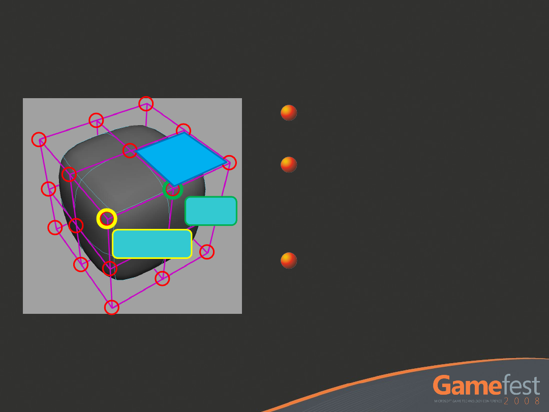
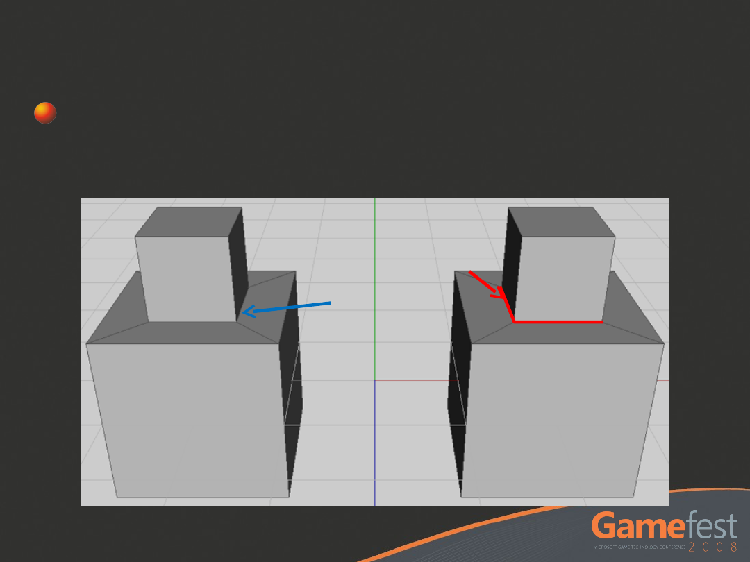
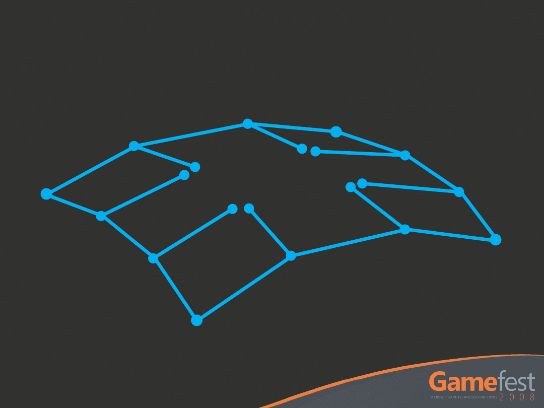
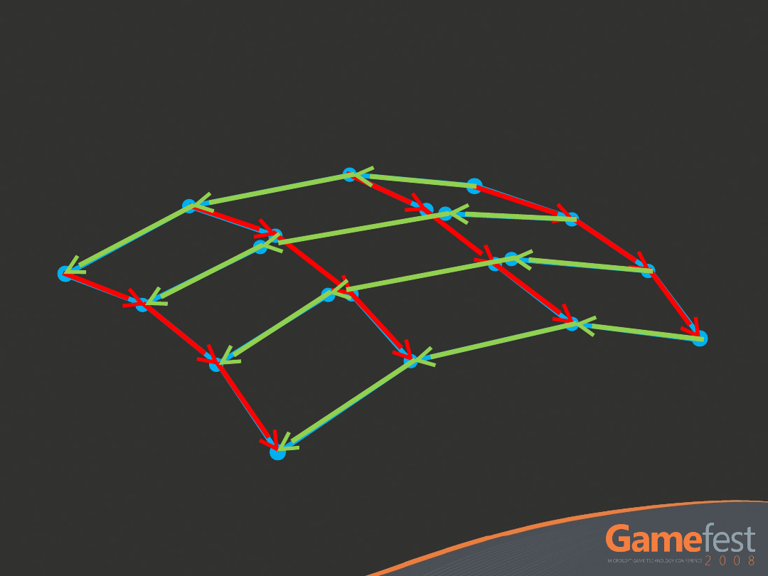
Quad Mesh
Quad Mesh
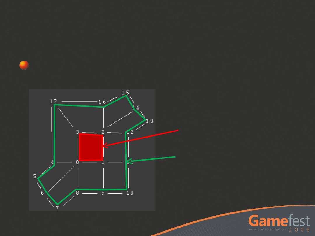
Input Quads
Input Quads
Each patch consists of 4 inner
quad vertices and a 1-ring
neighborhood
Sub-D Patch
1-Ring
Neighborhood
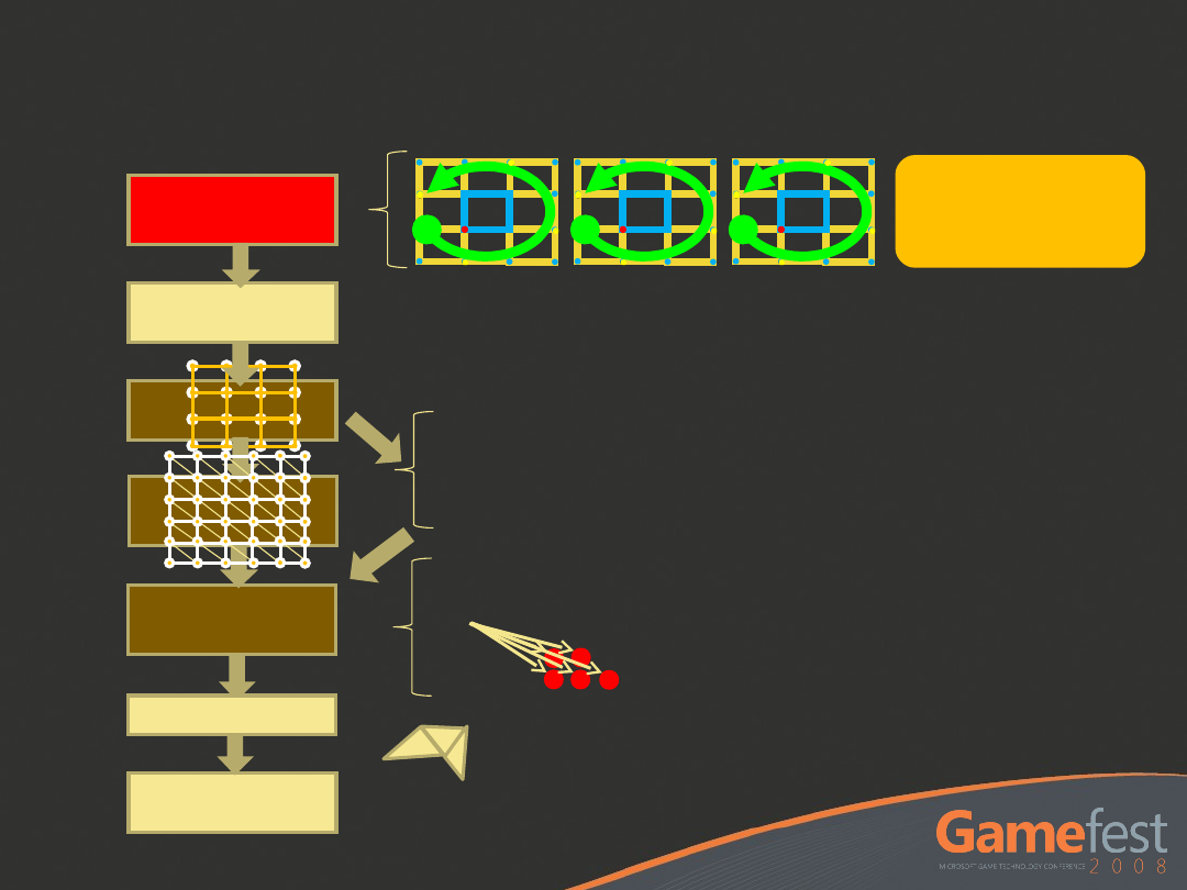
D3D11 Sub-D Pipeline
D3D11 Sub-D Pipeline
Overview
Overview
Hull Shader
VS
Tessellator
Sub-D
Patch
Buffer
PS
Domain
Shader
Dra
w
GS
o Single pass
o No additional memory
o Avoids 16 fetches per vertex
o Variable tessellation within a draw
o Subsets of HS can operate in
parallel
Skin

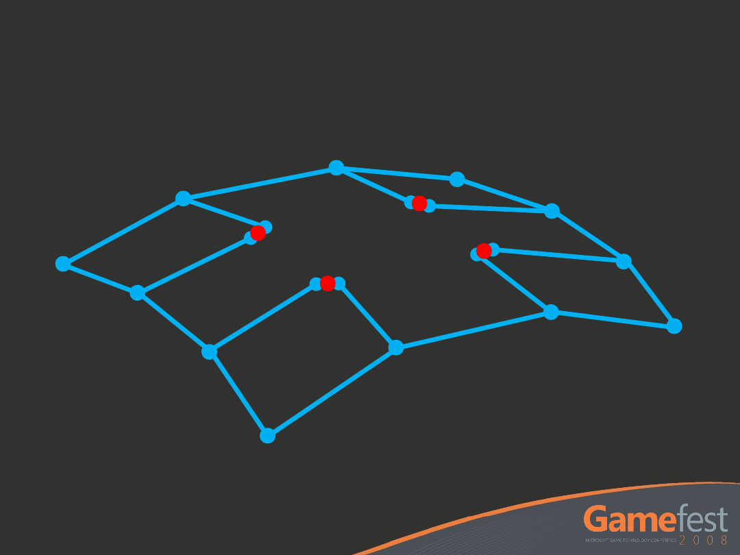
Regular and Extraordinary
Regular and Extraordinary
Regular patches
All vertices have 4 edge-adjacent
neighbors
Valence 4
Predictable amount of data and work
Extraordinary patches
Any irregular patch
Not quite as predictable
Require a little more work
Draw call per valence supported

Direct3D 10 SDK
Sample
Subdivision Surfaces
demo
Handling Creases
Handling Creases
Add redundant geometry
Defined
crease
Redundan
t
geometry

More Loop/Schaefer
More Loop/Schaefer
Research
Research
Latest version:
Modified Approximate Catmull-Clark
Patches (ACC2)
Outputs a Bezier patch consisting of
16 control vertices for regular
patches
Outputs a Gregory patch consisting of
20 control vertices for extraordinary
patches
New Research (ACC2)
New Research (ACC2)
Collapse position
and tangent into a
single bicubic patch
Fewer control
points, less memory
Modification of a
Gregory patch
Bicubic patch with 2
sets of interior knots
(20 knots total)
b
10
b
00
b
20
b
30
b
01
b
11v
b
11u
b
21v
b
21u
b
02
b
03
b
13
b
23
b
33
b
32
b
31
b
12v
b
12u
b
22v
b
22u
ACC2 Patch
ACC2 Patch
ACC2 Patch - Position
ACC2 Patch - Position
Average the inner point pairs and evaluate the
resulting 4x4 bicubic patch for position
ACC2 Patch - Tangents
ACC2 Patch - Tangents
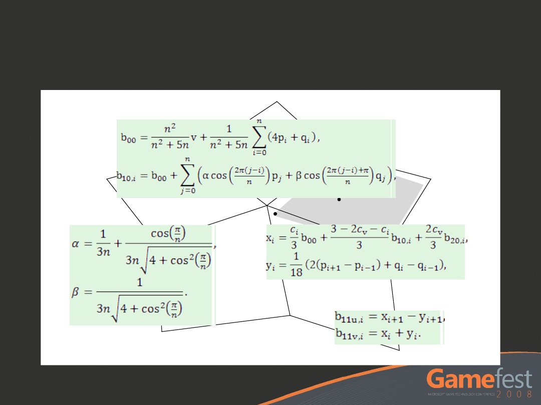
ACC2 Math
ACC2 Math
v
p
i
p
i+1
p
i-1
q
i
b
00
b
10,i
b
10,i+1
b
20,i
b
20,i+1
b
11v,i
b
11u,i
q
i-1

This is a lot…
This is a lot…
There’s a lot of complexity here, but
it’s worth it
D3D11 can target almost any surface
algorithm you want
Bezier
NURBs
Dynamic and static tessellation
Displacement
Subdivision (using Loop transforms)
and more…

Call to Action!
Call to Action!
Experiment with the D3D10
Subdivision Surface Sample from the
DirectX SDK NOW!
Build support for Sub-D meshes into
your pipelines, tools, and engines.
Look for a future Community Tech
Preview (CTP) of Direct3D 11.

© 2008 Microsoft Corporation. All rights reserved.
This presentation is for informational purposes only.
Microsoft makes no warranties, express or implied, in this
summary.
Document Outline
- Slide 1
- Slide 2
- Slide 3
- Slide 4
- Slide 5
- Slide 6
- Slide 7
- Slide 8
- Slide 9
- Slide 10
- Slide 11
- Slide 12
- Slide 13
- Slide 14
- Slide 15
- Slide 16
- Slide 17
- Slide 18
- Slide 19
- Slide 20
- Slide 21
- Slide 22
- Slide 23
- Slide 24
- Slide 25
- Slide 26
- Slide 27
- Slide 28
- Slide 29
- Slide 30
- Slide 31
- Slide 32
- Slide 33
- Slide 34
- Slide 35
- Slide 36
- Slide 37
- Slide 38
- Slide 39
- Slide 40
- Slide 41
Wyszukiwarka
Podobne podstrony:
Direct3D 11 Tessellation ppsx
Direct3D 11 Tessellation
Introduction to the Direct3D 11 Graphics Pipeline
Introduction to the Direct3D 11 Graphics Pipeline
CIA Director of HR 9 11 Commish Interview
ZAJĘCIA 11 Active Directory modyf
11 Dribbling and Changes of Direction
Zarz[1] finan przeds 11 analiza wskaz
11 Siłowniki
11 BIOCHEMIA horyzontalny transfer genów
PKM NOWY W T II 11
wyklad 11
R1 11
CALC1 L 11 12 Differenial Equations
więcej podobnych podstron