GASOLINE FUEL
SYSTEM
GM 2.4L ENGINE
S2.0-3.5FT (S40-70FT, S55FTS ) [F187];
H2.0-3.5FT (H40-70FT) [L177]
PART NO. 1580508
900 SRM 1126

SAFETY PRECAUTIONS
MAINTENANCE AND REPAIR
• When lifting parts or assemblies, make sure all slings, chains, or cables are correctly
fastened, and that the load being lifted is balanced. Make sure the crane, cables, and
chains have the capacity to support the weight of the load.
• Do not lift heavy parts by hand, use a lifting mechanism.
• Wear safety glasses.
• DISCONNECT THE BATTERY CONNECTOR before doing any maintenance or repair
on electric lift trucks. Disconnect the battery ground cable on internal combustion lift
trucks.
• Always use correct blocks to prevent the unit from rolling or falling. See HOW TO PUT
THE LIFT TRUCK ON BLOCKS in the Operating Manual or the Periodic Mainte-
nance section.
• Keep the unit clean and the working area clean and orderly.
• Use the correct tools for the job.
• Keep the tools clean and in good condition.
• Always use HYSTER APPROVED parts when making repairs. Replacement parts
must meet or exceed the specifications of the original equipment manufacturer.
• Make sure all nuts, bolts, snap rings, and other fastening devices are removed before
using force to remove parts.
• Always fasten a DO NOT OPERATE tag to the controls of the unit when making repairs,
or if the unit needs repairs.
• Be sure to follow the WARNING and CAUTION notes in the instructions.
• Gasoline, Liquid Petroleum Gas (LPG), Compressed Natural Gas (CNG), and Diesel fuel
are flammable. Be sure to follow the necessary safety precautions when handling these
fuels and when working on these fuel systems.
• Batteries generate flammable gas when they are being charged. Keep fire and sparks
away from the area. Make sure the area is well ventilated.
NOTE: The following symbols and words indicate safety information in this
manual:
WARNING
Indicates a condition that can cause immediate death or injury!
CAUTION
Indicates a condition that can cause property damage!

Gasoline Fuel System
Table of Contents
TABLE OF CONTENTS
General ...............................................................................................................................................................
Electronic Throttle Body Repair .......................................................................................................................
Electronic Throttle Body ...............................................................................................................................
Remove.......................................................................................................................................................
Install .........................................................................................................................................................
Fuel System Repair............................................................................................................................................
Before Repair Procedure ...............................................................................................................................
After Repair Procedure..................................................................................................................................
Fuel Leakage Check ..................................................................................................................................
Fuel Line Pressure Check .............................................................................................................................
Fuel Injectors .................................................................................................................................................
Remove.......................................................................................................................................................
Install .........................................................................................................................................................
Pressure Regulator ........................................................................................................................................
Remove.......................................................................................................................................................
Install .........................................................................................................................................................
Control System...................................................................................................................................................
Electronic Control Unit (ECU)......................................................................................................................
Remove.......................................................................................................................................................
Install .........................................................................................................................................................
Power Latch Relay.........................................................................................................................................
Remove.......................................................................................................................................................
Install .........................................................................................................................................................
Camshaft Position (CMP) Sensor .................................................................................................................
Remove.......................................................................................................................................................
Install .........................................................................................................................................................
Manifold Absolute Pressure (MAP)/Manifold Air Temperature (MAT) Sensor .........................................
Remove.......................................................................................................................................................
Install .........................................................................................................................................................
Engine Coolant Temperature (ECT) Sensor.................................................................................................
Remove.......................................................................................................................................................
Install .........................................................................................................................................................
Oxygen Sensor ...............................................................................................................................................
Remove.......................................................................................................................................................
Install .........................................................................................................................................................
This section is for the following models:
S2.0-3.5FT (S40-70FT, S55FTS ) [F187];
H2.0-3.5FT (H40-70FT) [L177]
©2005 HYSTER COMPANY
i

"THE
QUALITY
KEEPERS"
HYSTER
APPROVED
PARTS
900 SRM 1126
Electronic Throttle Body Repair
General
This section has the repair procedures for the parts of the gasoline fuel system used on the GM 2.4 liter engines.
Electronic Throttle Body Repair
ELECTRONIC THROTTLE BODY
Remove
1.
Disconnect the negative battery cable.
2.
Remove the clean air tube from the throttle body
to the air filter assembly.
3.
Disconnect the electrical connector from the
throttle body.
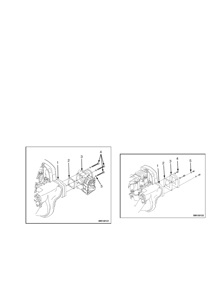
4.
Remove the socket head capscrews and lock-
washers retaining the throttle body to the
adapter plate. See Figure 1.
5.
Remove the throttle body and gasket. Discard
gasket.
6.
If necessary, remove the socket head capscrews
and lockwashers retaining the adapter plate to
the intake manifold. See Figure 2.
1.
ADAPTER PLATE
2.
GASKET
3.
ELECTRONIC THROTTLE BODY
4.
SOCKET HEAD CAPSCREWS
5.
LOCKWASHER
Figure 1. Electronic Throttle Body
7.
Remove the adapter plate and gasket.
Install
1.
Clean the mating surfaces of the intake manifold,
adapter plate, and the throttle body.
2.
If removed, place the new gasket and adapter
plate in position on the intake manifold.
3.
Install the lockwashers and socket head cap-
screws to retain the adapter plate. Tighten the
socket head capscrews to 10 N•m (88.5 lbf in).
4.
Place the new gasket and throttle body in posi-
tion on the adapter plate.
5.
Install the lockwashers and socket head cap-
screws. Tighten the socket head capscrews to
10 N•m (88.5 lbf in).
6.
Install the clean air tube.
7.
Connect the battery negative cable.
1.
INTAKE MANIFOLD
2.
GASKET
3.
ADAPTER PLATE
4.
SOCKET HEAD CAPSCREWS
5.
LOCKWASHER
Figure 2. Electronic Throttle Body
1
Fuel System Repair
900 SRM 1126
8.
Key ON the vehicle and with the PC service tool
send a "Restore ECU Defaults" command via the
CAN communication bus.
9.
Key OFF the vehicle and wait 30 seconds.
10. Connect the electrical connector to the throttle
body. Verify that the connector clicks/locks into
place.
WARNING
Do not insert fingers or foreign objects into the
throttle body.
11. Start the vehicle and check for proper operation
of the throttle body and the ECU by exercising
the accelerator pedal with the vehicle in neutral.
The engine should idle at 775 to 825 rpm with no
pedal to the governor speed of 2675 to 2725 rpm
at full pedal.
Fuel System Repair
BEFORE REPAIR PROCEDURE
WARNING
Fuel vapor is hazardous. It can easily ignite,
causing serious injury and damage.
Always
keep sparks and flames away from fuel.
Fuel line spills and leakage are dangerous.
Fuel can ignite and cause serious injuries or
death and damage. Fuel can also irritate skin
and eyes. To prevent this, always complete the
following procedures:
NOTE: Fuel in the fuel system is under high pres-
sure, including when the engine is not running.
1.
Remove the fuel-filler cap and release the pres-
sure in the fuel tank.
2.
Disconnect the electrical connector from the fuel
pump.
3.
Start the engine. After the engine stalls, crank
the engine several times.
4.
Turn the ignition to OFF position.
5.
Connect the electrical connector to the fuel pump.
AFTER REPAIR PROCEDURE
Fuel Leakage Check
WARNING
Fuel line spills and leakage are dangerous.
Fuel can ignite and cause serious injuries or
death and damage. Always perform the follow-
ing procedure with the engine stopped.
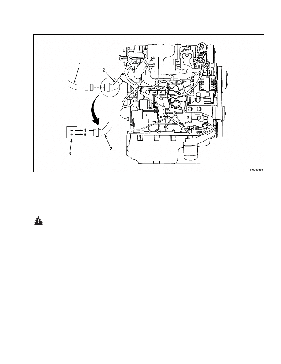
1.
Disconnect the 29-pin electrical connector that
is connecting the vehicle harness to the engine
harness. See Figure 3.
2.
Disconnect the electrical connector to the coil
pack.
CAUTION
To prevent arcing, only use jumper wires with
a momentary switch located within the wire.
3.
Install a jumper wire from pin 6 of the 29-pin con-
nector, on the engine harness side, to the posi-
tive battery terminal. Then install a jumper wire
from pin 4 of the 29-pin connector, on the engine
harness side, to the negative battery terminal.
See Figure 3.
4.
Pressurize the system this way for at least 5 min-
utes to be sure of no leakage. If there is fuel leak-
age, inspect the fuel hoses and fuel pipe sealing
surface for damage. Replace as needed.
5.
After repair, assemble the system and repeat
Step 1 through Step 4.
6.
Disconnect jumper wires.
7.
Connect the electrical connector to the coil pack.
8.
Connect the vehicle harness to the engine har-
ness.
2
900 SRM 1126
Fuel System Repair
1.
VEHICLE ELECTRICAL HARNESS AND 29-PIN CONNECTOR
2.
ENGINE ELECTRICAL HARNESS AND 29-PIN CONNECTOR
3.
BATTERY
Figure 3. 29-Pin Electrical Connector
FUEL LINE PRESSURE CHECK
WARNING
Fuel line spills and leakage are dangerous.
Fuel can ignite and cause serious injuries or
death.
Fuel can also irritate skin and eyes.
Always perform the following procedure with
the engine stopped.
1.
Complete the Before Repair Procedure.
2.
Disconnect the negative battery cable.
3.
Connect a fuel pressure gauge to the schrader
valve located on the outlet side of the fuel filter.
See Figure 4.
4.
Connect the negative battery cable.
5.
Turn the key switch to ON position to prime the
fuel pump.
6.
Measure the fuel line pressure. If less than the
specification, inspect the fuel pump for fuel line
leakage. If fuel line pressure exceeds the spec-
ification, inspect the pressure regulator for fuel
line clogging.
Specification: 379 to 448 kPa (55 to 65 psi)
7.
Turn the key switch to OFF position to stop the
fuel pump.
8.
Measure the fuel hold pressure after 5 minutes.
If not within the specification, inspect the fuel
line for clogging or leakage.
Specification: More than 300 kPa (43.5 psi)
9.
Disconnect the fuel pressure gauge.
10. Complete the After Repair Procedure.
3
Fuel System Repair
900 SRM 1126
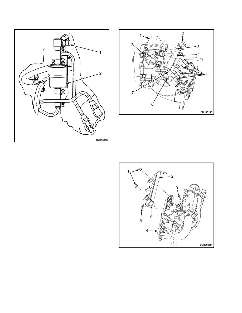
1.
SCHRADER VALVE
2.
FUEL FILTER
Figure 4. Schrader Valve Location
FUEL INJECTORS
Remove
1.
Complete the Before Repair Procedure.
2.
Disconnect the negative battery cable.
3.
Disconnect the positive crankcase ventilation
(PCV) valve hose from the intake manifold. See
Figure 5.
4.
Disconnect the vacuum hose from the pressure
regulator.
5.
Disconnect the wire harness connector from each
fuel injector.
6.
Disconnect the fuel inlet line and fuel return line.
7.
Remove the two capscrews retaining the fuel rail
to the intake manifold. See Figure 6.
8.
Remove the fuel rail and fuel injectors as an as-
sembly from the intake manifold.
1.
INTAKE MANIFOLD
2.
PRESSURE REGULATOR
3.
VACUUM HOSE
4.
PCV VALVE
5.
FUEL INJECTORS
6.
ELECTRICAL CONNECTOR
7.
FUEL RAIL
8.
ELECTRONIC THROTTLE BODY
Figure 5. Gasoline Fuel System
1.
CAPSCREWS
2.
FUEL RAIL
3.
ELECTRICAL CONNECTOR
4.
INTAKE MANIFOLD
5.
PRESSURE REGULATOR
6.
FUEL INJECTOR
Figure 6. Fuel Rail Assembly Remove/Install
4
900 SRM 1126
Fuel System Repair
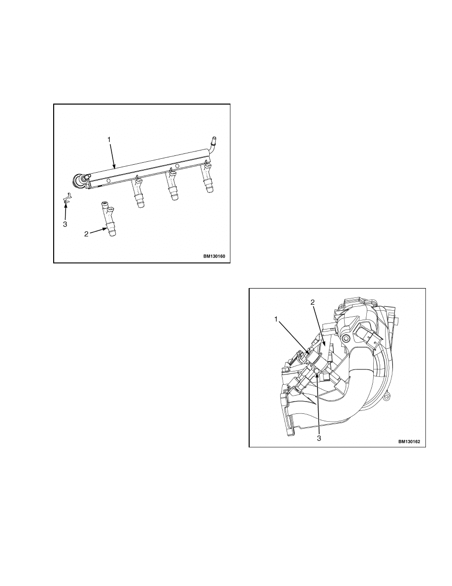
9.
Slide the fuel injector retaining clips off the fuel
injectors.
10. Remove the fuel injectors from the fuel rail. See
1.
FUEL RAIL
2.
FUEL INJECTORS
3.
RETAINING CLIP
Figure 7. Fuel Rail and Fuel Injectors
11. Remove and discard the O-rings from the fuel
injectors.
Install
1.
Install new O-rings onto the fuel injectors.
2.
Apply a small amount of clean engine oil to the
O-rings and install fuel injectors into the fuel
rail.
3.
Install the fuel rail and fuel injectors as an as-
sembly onto the intake manifold. Install the two
retaining capscrews and tighten capscrews to
20 N•m (15 lbf ft).
4.
Connect the fuel inlet line and fuel return line.
5.
Connect the wire harness connectors to each fuel
injector.
6.
Connect the vacuum hose to the pressure regula-
tor.
7.
Connect the PCV valve hose to the intake mani-
fold.
8.
Connect the negative battery cable.
9.
Complete the After Repair Procedure.
PRESSURE REGULATOR
Remove
1.
Complete the Before Repair Procedure.
2.
Disconnect the negative battery cable.
3.
Disconnect vacuum hose from pressure regula-
tor.
4.
Disconnect the fuel return line from pressure
regulator.
5.
Remove capscrew retaining pressure regulator to
fuel rail. See Figure 8.
6.
Remove pressure regulator from fuel rail.
7.
Remove and discard O-ring from pressure regu-
lator.
1.
PRESSURE REGULATOR
2.
FUEL RAIL
3.
CAPSCREW
Figure 8. Pressure Regulator
5
Control System
900 SRM 1126
Install
1.
Apply a light coat of clean engine oil to new
O-ring and install O-ring on pressure regulator.
2.
Place the pressure regulator in position on the
fuel rail and install capscrew to retain the pres-
sure regulator to the fuel rail. Tighten capscrew
to 9.4 N•m (83 lbf in).
3.
Connect the fuel return line to pressure regula-
tor.
4.
Connect vacuum hose to pressure regulator.
5.
Connect the negative battery cable.
6.
Complete the After Repair Procedure.
Control System
ELECTRONIC CONTROL UNIT (ECU)
Remove
1.
Disconnect the negative battery cable.
2.
Disconnect the electrical connector to the fuel
pump and fuel level sender.
3.
Disconnect the throttle body electrical connector.
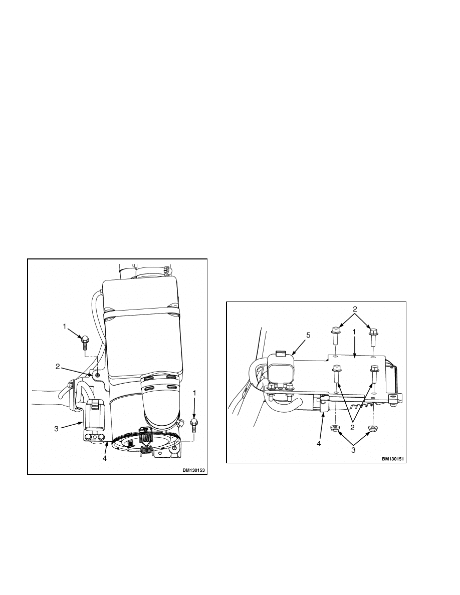
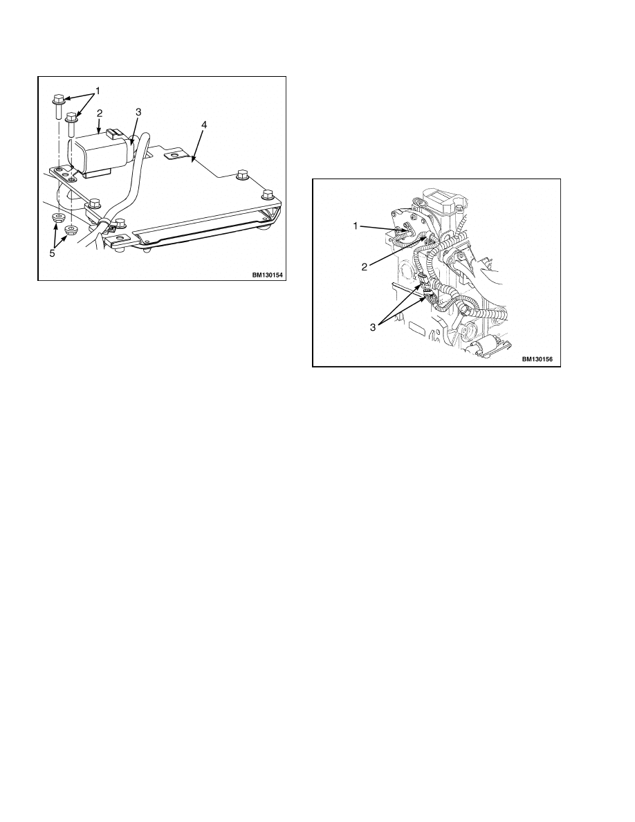
1.
CAPSCREW
2.
AIR FILTER MOUNTING BRACKET
3.
POWER LATCH RELAY
4.
ECU MOUNTING BRACKET
Figure 9. Air Filter Mounting Bracket and
ECU Mounting Bracket
4.
Remove the capscrews holding the air filter
mounting bracket to the ECU mounting bracket.
See Figure 9.
5.
Lower the ECU and mounting bracket assembly
down toward the frame.
6.
Disconnect the hoses from the air filter assembly.
7.
Remove the three bolts that attach the air filter
assembly mounting bracket to the frame and re-
move air filter assembly with mounting bracket.
8.
Remove the capscrews and nuts holding the ECU
to the mounting bracket. See Figure 10.
1.
MOUNTING BRACKET
2.
CAPSCREW
3.
NUTS
4.
ECU
5.
POWER LATCH RELAY
Figure 10. ECU Mounting Bracket
6
900 SRM 1126
Control System
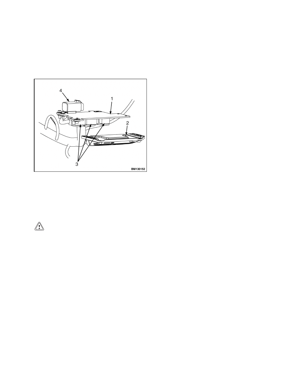
9.
Disconnect the electrical connectors from the
ECU. Rotate the locking tabs on each connector
to unlock the electrical connectors. Disconnect
the connector closest to the fan assembly first.
Disconnect the center connector second.
Dis-
connect the third connector. Remove ECU. See
Figure 11.
1.
MOUNTING BRACKET
2.
ECU
3.
ELECTRICAL CONNECTORS
4.
POWER LATCH RELAY
Figure 11. ECU and Electrical Connectors
Install
CAUTION
The electrical connectors should connect to the
ECU without any resistance. Do not force the
connectors in position as this can damage the
connector and/or the ECU.
1.
Connect the electrical connectors to the ECU.
Connect the electrical connector farthest from
the fan assembly first. Connect the center con-
nector second. Connect the connector closest to
the fan assembly last. Rotate the locking tabs to
lock the electrical connectors in position.
2.
Place the ECU in position on the mounting
bracket. Install the capscrews and nuts. Tighten
capscrews to 10 N•m (89 lbf in).
3.
Place the air filter assembly with mounting
bracket in position on the frame. Install bolts
and tighten to 20 N•m (15 lbf ft).
4.
Connect the hoses to the air filter assembly.
5.
Slide the ECU and mounting bracket assembly
into position on the air filter mounting bracket.
6.
Install the capscrews to retain the ECU mount-
ing bracket to the air filter mounting bracket.
Tighten capscrews to 20 N•m (15 lbf ft).
7.
Connect the negative battery cable.
8.
Key ON the vehicle and with the PC service tool
send a "Restore ECU Defaults" command via the
CAN communication bus.
9.
Key OFF the vehicle and wait 30 seconds.
10. Connect the throttle body electrical connector.
11. Start the vehicle and check for proper operation
of the throttle body and the ECU by exercising
the accelerator pedal with the vehicle in neutral.
The engine should idle at 775 to 825 rpm with no
pedal to the governed speed of 2675 to 2725 rpm
at full pedal.
POWER LATCH RELAY
Remove
1.
Disconnect the negative battery cable.
2.
Remove the capscrews holding the air filter
mounting bracket to the ECU mounting bracket.
See Figure 9.
3.
Lower the ECU and mounting bracket assembly
down toward the frame.
4.
Disconnect the hoses from the air filter assembly.
5.
Remove the three bolts that attach the air filter
assembly mounting bracket to the frame and re-
move air filter assembly with mounting bracket.
6.
Remove the capscrews and nuts retaining the
power latch relay to the ECU mounting bracket.
See Figure 12.
7
Control System
900 SRM 1126
1.
CAPSCREWS
2.
POWER LATCH RELAY
3.
ELECTRICAL CONNECTOR
4.
ECU MOUNTING BRACKET
5.
NUTS
Figure 12. Power Latch Relay
7.
Disconnect the electrical connector from the
power latch relay.
Install
1.
Connect the electrical connector from the power
latch relay.
2.
Place the power latch relay in position on the
ECU mounting bracket.
3.
Install capscrews and nuts to retain the power
latch relay to the ECU mounting bracket.
Tighten capscrews to 10 N•m (89 lbf in).
4.
Place the air filter assembly with mounting
bracket in position on the frame. Install bolts
and tighten to 20 N•m (14.75 lbf ft).
5.
Connect the hoses to the air filter assembly.
6.
Slide the ECU and mounting bracket assembly
into position on the air filter mounting bracket.
7.
Install the capscrews to retain the ECU mount-
ing bracket to the air filter mounting bracket.
Tighten capscrews to 20 N•m (15 lbf ft).
8.
Connect the negative battery cable.
CAMSHAFT POSITION (CMP) SENSOR
Remove
1.
Disconnect the negative battery cable.
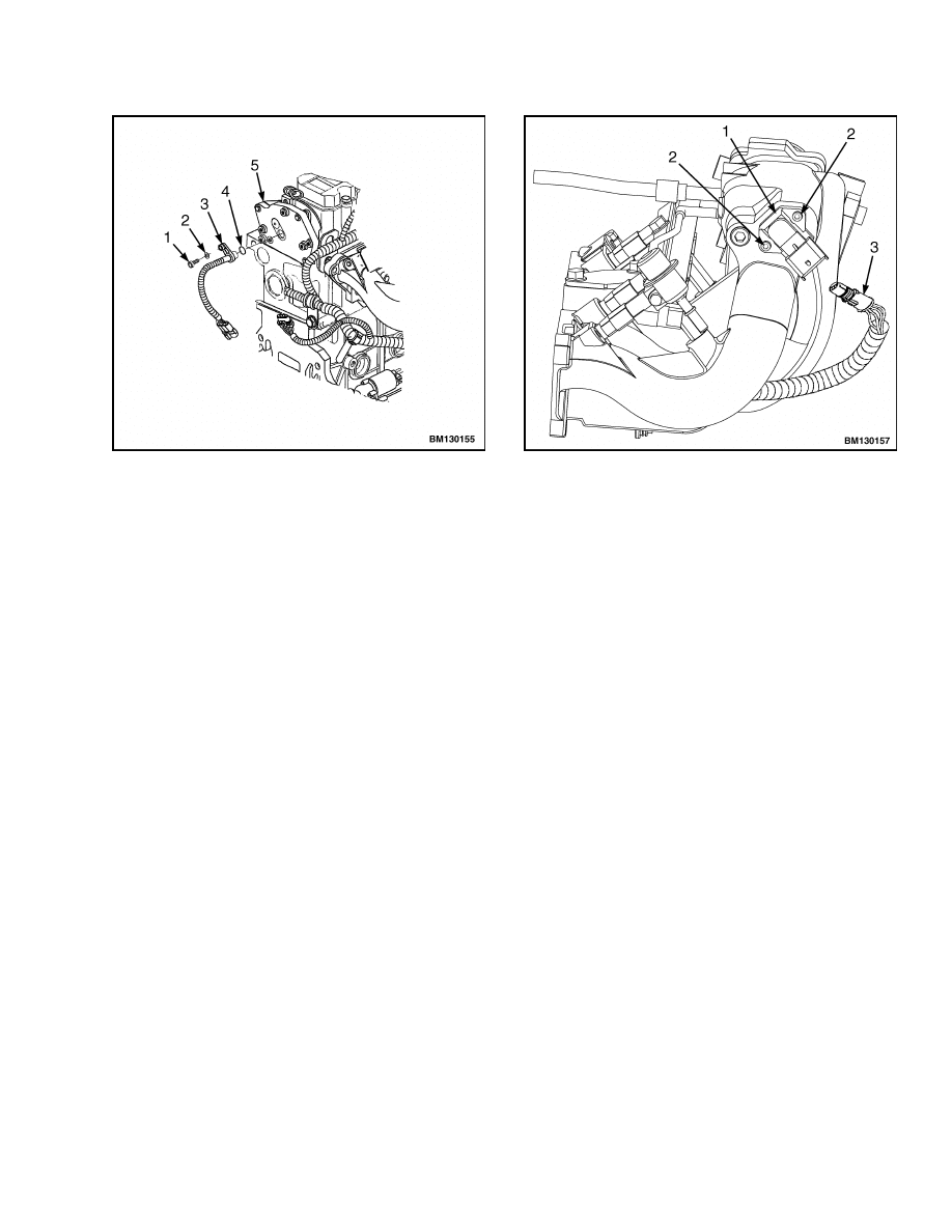
2.
Disconnect the CMP sensor electrical connector.
See Figure 13.
1.
CMP SENSOR
2.
WIRE HARNESS CLAMP
3.
ELECTRICAL CONNECTORS
Figure 13. CMP Sensor Electrical Connector
3.
Remove harness clamp from CMP sensor support
plate.
4.
Remove the screw and lockwasher retaining the
CMP sensor. See Figure 14.
5.
Remove the CMP sensor and O-ring by pulling
the CMP sensor and O-ring assembly straight
out of the CMP sensor support plate.
6.
Remove O-ring from CMP sensor and discard.
Install
1.
Install new O-ring on CMP sensor.
2.
Lubricate O-ring with clean engine oil.
3.
Install the CMP sensor into the CMP sensor sup-
port plate.
8
900 SRM 1126
Control System
1.
SCREW
2.
LOCKWASHER
3.
CMP SENSOR
4.
O-RING
5.
CMP SENSOR SUPPORT PLATE
Figure 14. CMP Sensor
NOTE: Before installing retaining screw, verify the
CMP sensor is fully seated.
4.
Install retaining screw and lockwasher. Tighten
retaining screw to 6 N•m (53 lbf in).
5.
Connect the electrical connector to the CMP con-
nector. Verify that the connectors click/lock into
place.
6.
Install harness clamp to CMP sensor support
plate.
MANIFOLD ABSOLUTE PRESSURE
(MAP)/MANIFOLD AIR TEMPERATURE
(MAT) SENSOR
Remove
1.
Disconnect the negative battery cable.
2.
Disconnect the electrical connector from the
MAP/MAT sensor. See Figure 15.
3.
Remove the two screws retaining the MAP/MAT
sensor to the intake manifold.
Remove MAP/
MAT sensor.
1.
MAP/MAT SENSOR
2.
SCREW
3.
ELECTRICAL CONNECTOR
Figure 15. MAP/MAT Sensor
Install
1.
Place the MAP/MAT sensor in position on the
intake manifold and install the two retaining
screws.
Tighten retaining screws to 6 N•m
(53 lbf in).
2.
Connect
the
electrical
connector
to
the
MAP/MAT sensor.
Verify that the connector
clicks/locks into place.
3.
Connect the negative battery cable.
ENGINE COOLANT TEMPERATURE (ECT)
SENSOR
Remove
1.
Disconnect the negative battery cable.
2.
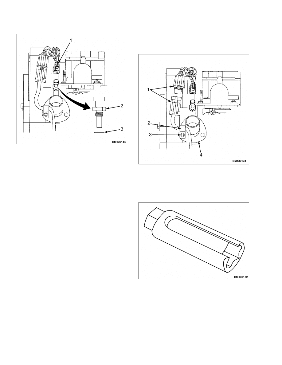
Disconnect the electrical connector from the ECT
sensor. See Figure 16.
3.
Remove the ECT sensor and washer.
9
Control System
900 SRM 1126
1.
ELECTRICAL CONNECTOR
2.
ECT SENSOR
3.
WASHER
Figure 16. ECT Sensor
Install
1.
Install the new ECT sensor and washer. Tighten
the sensor to 20 N•m (15 lbf ft).
2.
Connect the electrical connector to the ECT sen-
sor.
3.
Connect the negative battery cable.
OXYGEN SENSOR
Remove
1.
Disconnect the negative battery cable.
2.
Disconnect the oxygen sensor electrical connec-
tor. See Figure 17.
3.
Remove nut and clip retaining the oxygen sensor
wiring harness and connector to the thermostat
housing.
4.
Using a special tool, oxygen sensor socket, re-
move the oxygen sensor. See Figure 18 and Fig-
ure 19.
1.
ELECTRICAL CONNECTORS
2.
CLIP
3.
NUT
4.
THERMOSTAT HOUSING
Figure 17. Oxygen Sensor Electrical Connector
Figure 18. Oxygen Sensor Socket
10
900 SRM 1126
Control System
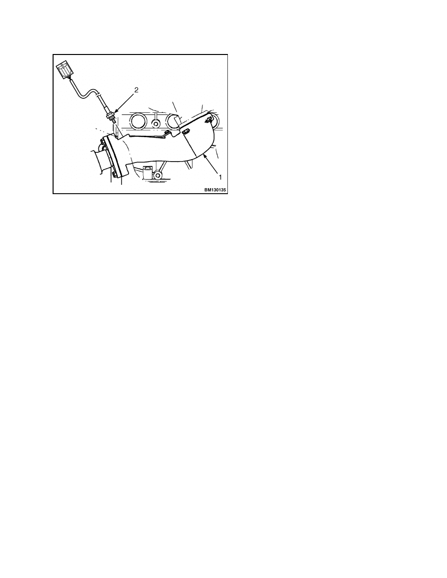
1.
EXHAUST MANIFOLD ADAPTER
2.
OXYGEN SENSOR
Figure 19. Oxygen Sensor
Install
1.
Before installing the sensor, coat sensor spar-
ingly with an antiseize compound, then install
oxygen sensor into exhaust manifold adapter.
Using a special tool, oxygen sensor socket,
tighten oxygen sensor to 40 to 60 N•m (30 to
44 lbf ft). See Figure 18 and Figure 19.
2.
Install nut and clip to retain the oxygen sensor
wiring harness and connector to the thermostat
housing.
3.
Connect the electrical connectors. Verify that the
connectors click/lock into place.
4.
Verify that the wire is pulled up toward the ther-
mostat and away from any hot exhaust compo-
nents.
5.
Connect the negative battery cable.
11

NOTES
____________________________________________________________
____________________________________________________________
____________________________________________________________
____________________________________________________________
____________________________________________________________
____________________________________________________________
____________________________________________________________
____________________________________________________________
____________________________________________________________
____________________________________________________________
____________________________________________________________
____________________________________________________________
____________________________________________________________
____________________________________________________________
____________________________________________________________
____________________________________________________________
____________________________________________________________
____________________________________________________________
____________________________________________________________
____________________________________________________________
12


TECHNICAL PUBLICATIONS
900 SRM 1126
5/05 (12/04) Printed in U.S.A.
Document Outline
- toc
Wyszukiwarka
Podobne podstrony:
Gasoline Fuel System Mazda 0900SRM1127 (05 2005) US EN
1580506 0900SRM1124 (05 2005) UK EN
Hydraulic Gear Pump 1900SRM1136 (05 2005) US EN
Calibrations 8000SRM1134 (05 2005) US EN
1510466 1800SRM0985 (05 2005) UK EN
1580505 0700SRM1123 (05 2005) UK EN
897591 0900SRM0547 (02 2001) US EN
1580512 1600SRM1133 (05 2005) UK EN
więcej podobnych podstron