
Copyright © 1999 Wimborne Publishing Ltd and
Maxfield & Montrose Interactive Inc
EPE Online, Febuary 1999 - www.epemag.com - XXX
Volume 3 Issue 4
April 2001

Copyright
2001, Wimborne Publishing Ltd
(Allen House, East Borough, Wimborne, Dorset, BH21 1PF, UK)
and Maxfield & Montrose Interactive Inc.,
(PO Box 857, Madison, Alabama 35758, USA)
All rights reserved.
WARNING!
The materials and works contained within EPE Online — which are made
available by Wimborne Publishing Ltd and Maxfield & Montrose Interactive Inc —
are copyrighted. You are permitted to make a backup copy of the downloaded file
and one (1) hard copy of such materials and works for your personal use.
International copyright laws, however, prohibit any further copying or
reproduction of such materials and works, or any republication of any kind.
Maxfield & Montrose Interactive Inc and Wimborne Publishing Ltd have used
their best efforts in preparing these materials and works. However, Maxfield &
Montrose Interactive Inc and Wimborne Publishing Ltd make no warranties of
any kind, expressed or implied, with regard to the documentation or data
contained herein, and specifically disclaim, without limitation, any implied
warranties of merchantability and fitness for a particular purpose.
Because of possible variances in the quality and condition of materials and
workmanship used by readers, EPE Online, its publishers and agents disclaim
any responsibility for the safe and proper functioning of reader-constructed
projects based on or from information published in these materials and works.
In no event shall Maxfield & Montrose Interactive Inc or Wimborne Publishing Ltd
be responsible or liable for any loss of profit or any other commercial damages,
including but not limited to special, incidental, consequential, or any other
damages in connection with or arising out of furnishing, performance, or use of
these materials and works.
ISSN 0262 3617
PROJECTS . . . THEORY . . . NEWS . . .
COMMENTS . . . POPULAR FEATURES . . .
VOL. 30. No. 4 APRIL 2001
Cover illustration by Jonathan Robertson
Everyday Practical Electronics, April 2001
233
© Wimborne Publishing Ltd 2001. Copyright in all
drawings, photographs and articles published in
EVERYDAY PRACTICAL ELECTRONICS is fully
protected, and reproduction or imitations in whole or
in part are expressly forbidden.
Our May 2001 issue will be published on Thursday,
12 April 2001. See page 235 for details
Readers Services
)) Editorial and Advertisement Departments 243
www.epemag.wimborne.co.uk
EPE Online:
www.epemag.com
P
Prroojjeeccttss a
anndd C
Ciirrccuuiittss
WAVE SOUND EFFECT by Robert Penfold
Let the susurration of the waves soothe intrusions on your senses
INTRUDER ALARM CONTROL PANEL by John Griffiths
5-zone microcontrolled security system designed to meet
British Standards specifiction BS4737
SOUND TRIGGER by Owen Bishop
How to soundly lighten your darkness – another Top-Tenner project
Treat your tropical pets to a personalised 4-channel central heating system
INGENUITY UNLIMITED hosted by Alan Winstanley
12V Sealed Lead/Acid Charger; Audio Preamplifier; Model Police Car L.E.D.s
S
Seerriieess a
anndd F
Feea
attuurreess
NEW TECHNOLOGY UPDATE by Ian Poole
3-D liquid crystal displays become reality
PRACTICALLY SPEAKING by Robert Penfold
A novice’s guide to trouble-shooting project assembly
CIRCUIT SURGERY by Alan Winstanley and Ian Bell
More on phase-locked loops
NET WORK – THE INTERNET PAGE surfed by Alan Winstanley
THE SCHMITT TRIGGER – 6. Further Digital Applications
by Anthony H. Smith
A designers’ guide to investigating and using Schmitt triggers
R
Reegguulla
arrss a
anndd S
Seerrvviicceess
NEWS – Barry Fox highlights technology’s leading edge
Plus everyday news from the world of electronics
READOUT John Becker addresses general points arising
SHOPTALK with David Barrington
PLEASE TAKE NOTE Doorbell Extender; Body Detector
Essential reference works for hobbyists, students and service engineers
BACK ISSUES Did you miss these? Some now on CD-ROM!
Teach-In 2000; Electronic Projects; Filters; Digital Works 3.0; Parts
Gallery + Electronic Circuits and Components; Digital Electronics; Analogue
Electronics; PICtutor; Modular Circuit Design; Electronic Components Photos;
C for PIC Micros; CAD Pack
DIRECT BOOK SERVICE
A wide range of technical books available by mail order
PRINTED CIRCUIT BOARD AND SOFTWARE SERVICE
ADVERTISERS INDEX
308
F
Frreeee S
Suup
pp
plleem
meenntt
AN END TO ALL DISEASE by Aubrey Scoon
between 270 and 271
Can disease be cured electronically? A story involving
electronics, blackmail, intimidation, government conspiracies,
arson, vandalism, theft, bribery and murder!

NO ONE DOES IT BETTER
DON'T MISS AN
ISSUE – PLACE YOUR
ORDER NOW!
Demand is bound to be high
MAY 2001 ISSUE ON SALE THURSDAY, APRIL 12
Everyday Practical Electronics, April 2001
235
PLUS ALL THE REGULAR FEATURES
NEXT MONTH
D.C. MOTOR
CONTROLLER
Inexpensive d.c. motors are often used by
model-makers, not only for model
locomotives and racing cars but in robots of
all kinds. They may also be used for driving
non-mobile models made from anything
from cardboard to Meccano. This project
controls a small 6V d.c. motor, but can be
used for 12V or high-voltage d.c. motors as
well. The circuit controls both the speed and
the direction of the motor. This Top Tenner
project is simple, easy to build and
inexpensive.
CAMCORDER MIXER
Modern camcorders, especially the digital variety, produce
pictures of a very high quality. However, the amateur often
spoils the finished result with inferior sound. It could be said
that most camcorder operators concentrate more on the visual
aspect than the sound, yet only if both are treated with equal
care will the video have a “professional’’ feel.
This circuit is a mixer which will combine the outputs of up to
two stereo microphones (or four mono ones) plus a stereo line
source and feed them into the camcorder. It may also be used
in conjunction with a domestic hi-fi system or power amplifier
for other purposes, such as karaoke. By using a well placed
microphone or microphones instead of the built-in camcorder
mic the sound on videos can be greatly improved.
PIC GRAPHICS
L.C.D. SCOPE
EPE
Feb ’01 contained a supplement in which the
author’s researches into Using Graphics L.C.D.s were
published. The PIC Graphics L.C.D. Scope (G-Scope) is
EPE
’s first example of putting such displays to practical
use. It is another addition to the widening family of simple
oscilloscope-type constructional projects published in
EPE
over the last few years.
G-Scope is a self-contained single-channel unit, catering
nominally for waveforms in the audio range and uses a
graphics l.c.d. screen having a pixel density of 64 x 128. It
also displays frequency and signal amplitude factors as
alphanumeric text lines. The signal source can be a.c. or
d.c. and waveforms up to 5V peak-to-peak can be input
without external attenuation. A simple pre-amp stage can
be switched to provide x1 or x10 amplification.
The control facilities include sync (waveform
synchronisation stability) on/off selection,
frequency/voltage monitoring on/off and a choice of three
sampling rates. The lowest sampling rate allows sub-Hertz
signals to be slowly traced on screen while they occur.
CROCODILE CLIPS. Small size, 10 each red and
black. Order Ref: 116.
PLASTIC HEADED CABLE CLIPS. Nail in type,
several sizes. Pack of 50. Order Ref: 123.
30A PANEL MOUNTING TOGGLE SWITCH.
Double pole. Order Ref: 166.
SUB MIN TOGGLE SWITCHES. Pack of 3. Order
Ref: 214.
HIGH POWER 3in. SPEAKER (11W 8ohm).
Order Ref: 246.
MEDIUM WAVE PERMEABILITY TUNER. It’s
almost a complete radio with circuit. Order Ref:
247.
PANEL METER. 0-1mA, scaled 0-100, face size
approximately 2¾in. square. Order Ref: 756.
MAINS MOTOR with gearbox giving 1 rev per 24
hours. Order Ref: 89.
ROUND POINTER KNOBS for flatted ¼in. spin-
dles. Pack of 10. Order Ref: 295.
CERAMIC WAVE CHANGE SWITCH. 12-pole, 3-
way with ¼in. spindle. Order Ref: 303.
REVERSING SWITCH. 20A double pole or 40A
single pole. Order Ref: 343.
LUMINOUS PUSH-ON PUSH-OFF SWITCHES.
Pack of 3. Order Ref: 373.
SLIDE SWITCHES. Single pole changeover. Pack
of 10. Order Ref: 1053.
PAXOLIN PANEL. Approximately 12in. x 12in.
Order Ref: 1033.
CLOCKWORK MOTOR. Suitable for up to 6
hours. Order Ref: 1038.
TRANSISTOR DRIVER TRANSFORMER.
Maker’s ref. no. LT44, impedance ratio 20k ohm to
1k ohm, centre tapped, 50p. Order Ref: 1/23R4.
HIGH CURRENT RELAY. 12V D.C. or 24V A.C.,
operates changeover contacts. Order Ref: 1026.
2-CORE CURLY LEAD. 5A, 2m. Order Ref: 846.
3 CHANGEOVER RELAY. 6V A.C., 3V D.C. Order
Ref: 859.
3 CONTACT MICRO SWITCHES, operated with
slightest touch. Pack of 2. Order Ref: 861.
HIVAC NUMICATOR TUBE. Hivac ref XN3. Order
Ref: 865.
2IN. ROUND LOUDSPEAKERS. 50
9 coil. Pack of
2. Order Ref: 908.
2IN. ROUND LOUDSPEAKERS. 8
9. Pack of 2.
Order Ref: 908/8.
5K POT, standard size with DP switch, good
length ¼in. spindle, pack of 2. Order Ref: 11R24.
13A PLUG, fully legal with insulated legs, pack of
3. Order Ref: GR19.
OPTO SWITCH on p.c.b., size 2in. x 1in., pack of
2. Order Ref: GR21.
1000W FIRE SPIRALS. In addition to repairing
fires, these are useful for making high current
resistors. Price 4 for £1. Order Ref: 223.
BRASS ENCASED ELEMENT. Mains working,
80W standard replacement in some fridges but
very useful for other heating purposes. Price £1
each. Order Ref: 8.
PEA LAMPS, only 4mm but 14V at 0·04A, wire
ended, pack of 4. Order Ref: 7RC28.
HIGH AMP THYRISTOR, normal 2 contacts from
top, heavy threaded fixing underneath, think
amperage to be at least 25A, pack of 2. Order Ref:
7FC43.
BRIDGE RECTIFIER, ideal for 12V to 24V charg-
er at 5A, pack of 2. Order Ref: 1070.
TEST PRODS FOR MULTIMETER with 4mm
sockets. Good length very flexible lead. Order Ref:
D86.
LUMINOUS ROCKER SWITCH, approximately
30mm square, pack of 2. Order Ref: D64.
MES LAMP HOLDERS, slide onto ¼in. tag, pack
of 10. Order Ref: 1054.
HALL EFFECT DEVICES, mounted on small
heatsink, pack of 2. Order Ref: 1022.
12V POLARISED RELAY, 2 changeover contacts.
Order Ref: 1032.
PROJECT CASE, 95mm x 66mm x 23mm with
removable lid held by 4 screws, pack of 2. Order
Ref: 876.
LARGE MICRO SWITCHES, 20mm x 6mm x
10mm, changeover contacts, pack of 2. Order Ref:
826.
PIEZO ELECTRIC SOUNDER, also operates effi-
ciently as a microphone. Approximately 30mm
diameter, easily mountable, 2 for £1. Order Ref:
1084.
LIQUID CRYSTAL DISPLAY on p.c.b. with ICs
etc. to drive it to give 2 rows of 8 characters, price
£1. Order Ref: 1085.
THIS MONTH’S SPECIAL
IT IS A DIGITAL
MULTITESTER, com-
plete with backrest to
stand it and hands-
free test prod holder.
This tester measures
d.c. volts up to 1,000
and a.c. volts up to
750; d.c. current up to
10A and resistance
up to 2 megs. Also
tests transistors and
diodes and has an
internal buzzer for
continuity tests. Comes complete with test prods,
battery and instructions. Price £6.99. Order Ref:
7P29.
12V DC POWER SUPPLY. 650mA regulated with
13A plug-in pins, £2.50. Order Ref: 2.5P26.
VERY THIN DRILLS.
12 assor ted sizes vary
between 0·6mm and 1·6mm. Price £1. Order Ref:
128.
EVEN THINNER DRILLS. 12 that vary between
0·1mm and 0·5mm. Price £1. Order Ref:129.
BT PLUG WITH TWIN SOCKET. Enables you to
plug 2 telephones into the one socket for all normal
BT plugs. Price £1.50. Order Ref: 1.5P50.
D.C. MOTOR WITH GEARBOX. Size 60mm long,
30mm diameter. Very powerful, operates off any
voltage between 6V and 24V D.C. Speed at 6V is
200 rpm, speed controller available. Special price
£3 each. Order Ref: 3P108.
FLASHING BEACON. Ideal for putting on a van, a
tractor or any vehicle that should always be seen.
Uses a Xenon tube and has an amber coloured
dome. Separate fixing base is included so unit can
be put away if desirable. Price £5. Order Ref: 5P267.
MOST USEFUL POWER SUPPLY. Rated at 9V 1A,
this plugs into a 13A socket, is really nicely boxed.
£2. Order Ref: 2P733.
MOTOR SPEED CONTROLLER. These are suitable
for D.C. motors for voltages up to 12V and any
power up to 1/6h.p. They reduce the speed by inter-
mittent full voltage pulses so there should be no
loss of power. In kit form these are £12. Order Ref:
12P34. Or made up and tested, £20. Order Ref:
20P39.
BT TELEPHONE EXTENSION WIRE. This is proper
heavy duty cable for running around the skirting
board when you want to make a permanent exten-
sion. 4 cores properly colour coded, 25m length.
Only £1. Order Ref:1067.
FOR QUICK HOOK-UPS. You can’t beat leads with
a croc clip each end.
You can have a set of
10 leads, 2 each of 5
assor ted colours with
insulated crocodile clips
on each end.
Lead
length 36cm, £2 per
set. Order Ref: 2P459.
BALANCE ASSEMBLY KITS. Japanese made,
when assembled ideal for chemical experiments,
complete with tweezers and 6 weights 0·5 to 5
grams. Price £2. Order Ref: 2P44.
CYCLE LAMP BARGAIN. You can have 100 6V 0-
5A MES bulbs for just £2.50 or 1,000 for £20. They
are beautifully made, slightly larger than the stan-
dard 6·3V pilot bulb so they would be ideal for mak-
ing displays for night lights and similar applications.
DOORBELL PSU. This has AC voltage output so is
ideal for operating most doorbells. The unit is totally
enclosed so perfectly safe and it plugs into a 13A
socket. Price only £1. Order Ref: 1/30R1.
INSULATION TESTER WITH MULTIMETER.
Internally generates voltages which enable you to
read insulation directly in megohms. The multi-
meter has four ranges, AC/DC volts, 3 ranges DC
milliamps, 3 ranges resistance and 5 amp range.
These instruments are ex-British Telecom but in
very good condition, tested and guaranteed OK,
probably cost at least £50 each, yours for only £7.50
with leads, carrying case £2 extra. Order Ref: 7.5P4.
REPAIRABLE METERS. We have some of the
above testers but slightly faulty, not working on all
ranges, should be repairable, we supply diagram,
£3. Order Ref: 3P176.
TWO MORE POST OFFICE INSTRUMENTS
Both instruments contain lots of useful parts, includ-
ing sub-min toggle switch sold by many at £1 each.
They are both in extremely nice cases, with battery
compartment and flexible carrying handles, so if you
don’t need the intruments themselves, the case may
be just right for a project you have in mind.
The first is Oscillator 87F. This has an output, con-
tinuous or interrupted, of 1kHz. It is in a plastic box
size 115mm wide, 145mm high and 50mm deep.
Price only £1. Order Ref: 7R1.
The other is Amplifier Ref. No. 109G. This is in a
case size 80mm wide, 130mm high and 35mm deep.
Price £1. Order Ref: 7R2.
HEAVY DUTY POT
Rated at 25W, this is 20 ohm resistance so it could
be just right for speed controlling a d.c. motor or
device or to control the output of a high current
amplifier. Price £1. Order Ref: 1/33L1.
STEPPER MOTOR
Made by Philips as specified for the wind-up torch in
the Oct ’00 Practical Electronics is still available,
price £2. Order Ref: 2P457.
SOLDERING IRON, super mains powered with
long-life ceramic element, heavy duty 40W for the
extra special job, complete with plated wire stand
and 245mm lead, £3. Order Ref: 3P221.
RELAYS
We have thousands of
relays of various sorts in
stock, so if you need any-
thing special give us a
ring. A few new ones that
have just arrived are spe-
cial in that they are plug-
in and come complete
with a special base which
enables you to check
voltages of connections of it without having to go
underneath. We have 6 different types with varying
coil voltages and contact arrangements. All contacts
are rated at 10A 250V AC.
Coil Voltage Contacts
Price
Order Ref:
12V DC
4-pole changeover
£2.00
FR10
24V DC
2-pole changeover
£1.50
FR12
24V DC
4-pole changeover
£2.00
FR13
240V AC
1-pole changeover
£1.50
FR14
240V AC
4-pole changeover
£2.00
FR15
Prices include base
NOT MUCH BIGGER THAN AN OXO CUBE. Another
relay just arrived is extra small with a 12V coil and 6A
changeover contacts. It is sealed so it can be mount-
ed in any position or on a p.c.b. Price 75p each, 10 for
£6 or 100 for £50. Order Ref: FR16.
RECHARGEABLE NICAD BATTERIES. AA size, 25p
each, which is a real bargain considering many firms
charge as much as £2 each. These are in packs of 10,
coupled together with an output lead so are a 12V unit
but easily divideable into 2 × 6V or 10 × 1·2V. £2.50
per pack, 10 packs for £25 including carriage. Order
Ref: 2.5P34.
TERMS
Send cash, PO, cheque or quote credit card number –
orders under £25 add £3.50 service charge.
J
J &
& N
N F
FA
AC
CT
TO
OR
RS
S
P
Piillg
grriim
m W
Wo
orrk
ks
s ((D
De
ep
ptt..E
E..E
E..))
S
Stta
aiirrb
brriid
dg
ge
e L
La
an
ne
e,, B
Bo
olln
ne
ey
y
S
Su
us
ss
se
ex
x R
RH
H1
17
7 5
5P
PA
A
T
Te
elle
ep
ph
ho
on
ne
e:: 0
01
14
44
44
4 8
88
81
19
96
65
5
E
E--m
ma
aiill:: jjn
nffa
ac
ctto
orrs
s@
@a
ao
oll..c
co
om
m
£
£1
1 B
BA
AR
RG
GA
AIIN
N P
PA
AC
CK
KS
S
S
Se
elle
ec
ctte
ed
d IItte
em
ms
s
Everyday Practical Electronics, April 2001
239
SMART HIGH QUALITY ELECTRONIC KITS
CAT.NO. DESCRIPTION
PRICE
£
1005
Touch Switch
2.87
1010
5-input stereo mixer
with monitor output
19.31
1016
Loudspeaker protection unit
3.22
1023
Dynamic head preamp
2.50
1024
MIcrophone preamplifier
2.07
1025
7 watt hi-fl power amplifier
2.53
1026
Running lights
4.60
1027
NiC.cad battery charger
3.91
1030
Light dimmer
2.53
1039
Stereo VU meter
4.60
1042
AF generator 250Hz-16kHz
1.70
1043
Loudness stereo unit
3.22
1047
Sound switch
5.29
1048
Electronic thermostat
3.68
1050
3-input hi-fl stereo preamplifier
12.42
1052
3-input mono mixer
6.21
1054
4-input instrument mixer
2.76
1059
Telephone amplifier
4.60
1062
5V 0·5A stabilised supply for TTL
2.30
1064
12V 0·5A stabilised supply
3.22
1067
Stereo VU meter with leads
9.20
1068
18V 0·5A stabilised power supply
2.53
1071
4-input selector
6.90
1080
Liquid level sensor, rain alarm
2.30
1082
Car voltmeter with l.e.d.s
7.36
1083
Video signal amplifier
2.76
1085
DC converter 12V to 6V or 7.5V or 9V
2.53
1093
Windscreen wiper controller
3.68
1094
Home alarm system
12.42
1098
Digital thermometer with l.c.d. display
11.50
1101
Dollar tester
4.60
1102
Stereo VU meter with 14 I.e.d.s
6.67
1106
Thermometer with l.e.d.s
6.90
1107
Electronics to help win the pools
3.68
1112
Loudspeaker protection with delay
4.60
1115
Courtesy light delay
2.07
1118
Time switch with triac 0-10 mins
4.14
1122
Telephone call relay
3.68
1123
Morse code generator
1.84
1126
Microphone preamplifier
4.60
1127
Microphone tone control
4.60
1128a
Power flasher 12V d.c.
2.53
1133
Stereo sound to light
5.26
) SUPER UPGRADE FROM V1 )18, 28 AND 40-PIN CHIPS
) READ, WRITE, ASSEMBLE & DISASSEMBLE PICS
) SIMPLE POWER SUPPLY OPTIONS 5V-20V
) ALL SWITCHING UNDER SOFTWARE CONTROL
) MAGENTA DESIGNED PCB HAS TERMINAL PINS AND
OSCILLATOR CONNECTIONS FOR ALL CHIPS
) INCLUDES SOFTWARE AND PIC CHIP
KIT 878 . . . £22.99 with 16F84 . . . £29.99 with 16F877
PIC 16C84 DISPLAY DRIVER
INCREDIBLE LOW PRICE! Kit 857 £
£1
12
2..9
99
9
SIMPLE PIC PROGRAMMER
Power Supply £3.99
EXTRA CHIPS:
PIC 16F84 £4.84
INCLUDES 1-PIC16F84 CHIP
SOFTWARE DISK, LEAD
CONNECTOR, PROFESSIONAL
PC BOARD & INSTRUCTIONS
Based on February ’96 EPE. Magenta designed PCB and kit. PCB
with ‘Reset’ switch, Program switch, 5V regulator and test L.E.D.s,
and connection points for access to all A and B port pins.
INCLUDES 1-PIC16F84 WITH
DEMO PROGRAM SOFTWARE
DISK, PCB, INSTRUCTIONS
AND 16-CHARACTER 2-LINE
LCD DISPLAY
Kit 860
£
£1
19
9..9
99
9
Power Supply
£3.99
FULL PROGRAM SOURCE
CODE SUPPLIED – DEVELOP
YOUR OWN APPLICATION!
Another super PIC project from Magenta. Supplied with PCB, industry
standard 2-LINE × 16-character display, data, all components, and
software to include in your own programs. Ideal development base for
meters, terminals, calculators, counters, timers – Just waiting for your
application!
PIC 16F84 MAINS POWER 4-CHANNEL
CONTROLLER & LIGHT CHASER
) WITH PROGRAMMED 16F84 AND DISK WITH
SOURCE CODE IN MPASM
) ZERO VOLT SWITCHING
MULTIPLE CHASE PATTERNS
) OPTO ISOLATED
5 AMP OUTPUTS
) 12 KEYPAD CONTROL
) SPEED/DIMMING POT.
) HARD-FIRED TRIACS
Kit 855
£
£3
39
9..9
95
5
Now features full 4-channel
chaser software on DISK and
pre-programmed PIC16F84
chip. Easily re-programmed
for your own applications.
Software source code is fully
‘commented’ so that it can be
followed easily.
LOTS OF OTHER APPLICATIONS
Tel: 01283 565435 Fax: 01283 546932 E-mail: sales@magenta2000.co.uk
Everyday Practical Electronics, April 2001
241
All prices include VAT. Add £3.00 p&p. Next day £6.99
E
EP
PE
E
P
PIIC
C T
Tu
utto
orriia
all
At last! A Real, Practical, Hands-On Series
)
Learn Programming from scrach using PIC16F84
)
Start by lighting l.e.d.s and do 30 tutorials to
Sound Generation, Data Display, and a Security
System.
)
PIC TUTOR Board with Switches, l.e.d.s, and on
board programmer
PIC TOOLKIT V2
PIC TUTOR BOARD KIT
Includes: PIC16F84 Chip, TOP Quality PCB printed with
Component Layout and all components* (*not ZIF Socket or
Displays). Included with the Magenta Kit is a disk with Test
and Demonstration routines.
KIT 870 .... £27.95, Built & Tested .... £42.95
Optional: Power Supply – £3.99, ZIF Socket – £9.99
LCD Display ........... £7.99 LED Display ............ £6.99
Reprints Mar/Apr/May 98 – £3.00 set 3
SUPER PIC PROGRAMMER
)
READS, PROGRAMS, AND VERIFIES
) WINDOWSK SOFTWARE
) PIC16C6X, 7X, AND 8X
) USES ANY PC PARALLEL PORT
) USES STANDARD MICROCHIP )HEX FILES
) OPTIONAL DISASSEMBLER SOFTWARE (EXTRA)
) PCB, LEAD, ALL COMPONENTS, TURNED-PIN
SOCKETS FOR 18, 28, AND 40 PIN ICs
) SEND FOR DETAILED
INFORMATION – A
SUPERB PRODUCT AT
AN UNBEATABLE LOW
PRICE.
Kit 862
£
£2
29
9..9
99
9
Power Supply £3.99
DISASSEMBLER
SOFTWARE
£11.75
PIC STEPPING MOTOR DRIVER
8-CHANNEL DATA LOGGER
INCLUDES PCB,
PIC16F84 WITH
DEMO PROGRAM,
SOFTWARE DISC,
INSTRUCTIONS
AND MOTOR.
Kit 863
£
£1
18
8..9
99
9
FULL SOURCE CODE SUPPLIED
ALSO USE FOR DRIVING OTHER
POWER DEVICES e.g. SOLENOIDS
Another NEW Magenta PIC project. Drives any 4-phase unipolar motor – up
to 24V and 1A. Kit includes all components and 48 step motor. Chip is
pre-programmed with demo software, then write your own, and re-program
the same chip! Circuit accepts inputs from switches etc and drives motor in
response. Also runs standard demo sequence from memory.
As featured in Aug./Sept. ’99
EPE. Full kit with Magenta
redesigned PCB – LCD fits directly on board. Use as Data
Logger
or as a test bed for many other 16F877 projects. Kit
includes programmed chip, 8 EEPROMs, PCB, case and all components.
KIT 877 £49.95
inc. 8 × 256K EEPROMS
NEW!
PIC Real Time
In-Circuit Emulator
* Icebreaker uses PIC16F877 in circuit debugger
* Links to Standard PC Serial Port (lead supplied)
* Windows
TM
(95+) Software included
* Works with MPASM and MPLAB Microchip software
* 16 x 2 L.C.D., Breadboard, Relay, I/O devices and patch leads supplied
As featured in March ’00
EPE. Ideal for beginners AND advanced users.
Programs can be written, assembled, downloaded into the microcontroller and run at full
speed (up to 20MHz), or one step at a time.
Full emulation means that all I/O ports respond exactly and immediately, reading and
driving external hardware.
Features include: Reset; Halt on external pulse; Set Breakpoint; Examine and Change
registers, EEPROM and program memory; Load program, Single Step with display of
Status, W register, Program counter, and user selected ‘Watch Window’ registers.
KIT 900 . . . £34.99
POWER SUPPLY
£3.99
STEPPING MOTOR
£5.99

Editorial Offices:
EVERYDAY PRACTICAL ELECTRONICS EDITORIAL
ALLEN HOUSE, EAST BOROUGH, WIMBORNE
DORSET BH21 1PF
Phone: Wimborne (01202) 881749. Fax: (01202) 841692.
E-mail: editorial@epemag.wimborne.co.uk
Web Site: http://www.epemag.wimborne.co.uk
EPE Online
www.epemag.com
EPE Online Shop: www.epemag.wimborne.co.uk/shopdoor.htm
See notes on Readers’ Enquiries below – we regret lengthy
technical enquiries cannot be answered over the telephone.
Advertisement Offices:
EVERYDAY PRACTICAL ELECTRONICS ADVERTISEMENTS
MILL LODGE, MILL LANE
THORPE-LE-SOKEN, ESSEX CO16 0ED
Phone/Fax: (01255) 861161
E-mail: epeads@aol.com
Editor: MIKE KENWARD
Deputy Editor: DAVID BARRINGTON
Technical Editor: JOHN BECKER
Business Manager: DAVID J. LEAVER
Subscriptions: MARILYN GOLDBERG
Administration: FAY KENWARD
Editorial/Admin: Wimborne (01202) 881749
Advertisement Manager:
PETER J. MEW, Frinton (01255) 861161
Advertisement Copy Controller:
PETER SHERIDAN, Wimborne (01202) 882299
On-Line Editor: ALAN WINSTANLEY
EPE Online (Internet version) Editors:
CLIVE (MAX) MAXFIELD and ALVIN BROWN
READERS’ ENQUIRIES
E-mail: techdept@epemag.wimborne.co.uk
We are unable to offer any advice on the use,
purchase, repair or modification of commercial
equipment or the incorporation or modification
of designs published in the magazine. We
regret that we cannot provide data or answer
queries on articles or projects that are more
than five years old. Letters requiring a personal
reply
must be accompanied by a stamped
self-addressed envelope or a self-
addressed envelope and international reply
coupons. All reasonable precautions are
taken to ensure that the advice and data given
to readers is reliable. We cannot, however,
guarantee it and we cannot accept legal
responsibility for it.
COMPONENT SUPPLIES
We do not supply electronic components or
kits for building the projects featured, these
can be supplied by advertisers (see
Shoptalk).
We advise readers to check that all parts are
still available before commencing any project
in a back-dated issue.
ADVERTISEMENTS
E-mail: adverts@epemag.wimborne.co.uk
Although the proprietors and staff of
EVERYDAY PRACTICAL ELECTRONICS take
reasonable precautions to protect the interests
of readers by ensuring as far as practicable
that advertisements are
bona fide, the maga-
zine and its Publishers cannot give any under-
takings in respect of statements or claims
made by advertisers, whether these advertise-
ments are printed as part of the magazine, or
in inserts.
The Publishers regret that under no circum-
stances will the magazine accept liability for
non-receipt of goods ordered, or for late
delivery, or for faults in manufacture.
TRANSMITTERS/BUGS/TELEPHONE
EQUIPMENT
We advise readers that certain items of radio
transmitting and telephone equipment which
may be advertised in our pages cannot be
legally used in the UK. Readers should check
the law before buying any transmitting or
telephone equipment as a fine, confiscation of
equipment and/or imprisonment can result
from illegal use or ownership. The laws vary
from country to country; readers should check
local laws.
AVAILABILITY
Copies of
EPE
are available on subscription anywhere
in the world (see below), from all UK newsagents
(distributed by COMAG) and from the following
electronic component retailers: Omni Electronics and
Yebo Electronics (S. Africa).
EPE
can also be pur-
chased from retail magazine outlets around the world.
An Internet on-line version can be purchased for just
$9.99(US) per year available from www.epemag.com
SUBSCRIPTIONS
Subscriptions for delivery direct to any address in the
UK: 6 months £14.50, 12 months £27.50, two years
£50; Overseas: 6 months £17.50 standard air service or
£27 express airmail, 12 months £33.50 standard air ser-
vice or £51 express airmail, 24 months £62 standard air
service or £97 express airmail.
Online subscriptions, for downloading the magazine via
the Internet, $9.99(US) for one year available from
www.epemag.com.
Cheques or bank drafts (in £ sterling only) payable to
Everyday Practical Electronics
and sent to EPE Sub.
Dept., Allen House, East Borough, Wimborne, Dorset
BH21 1PF. Tel: 01202 881749. Fax: 01202 841692. E-
mail: subs@epemag.wimborne.co.uk. Also via the Web
at: http://www.epemag.wimborne.co.uk. Subscriptions
start with the next available issue. We accept
MasterCard, Switch or Visa. (For past issues see the
Back Issues
page
.)
BINDERS
Binders to hold one volume (12 issues) are available
from the above address. These are finished in blue
p.v.c., printed with the magazine logo in gold on the
spine. Price £5.95 plus £3.50 p&p (for overseas readers
the postage is £6.00 to everywhere except Australia
and Papua New Guinea which cost £10.50).
Normally
sent within seven days but please allow 28 days for
delivery – more for overseas.
Payment in £ sterling only please. Visa, Switch and
MasterCard accepted, minimum credit card order
£5. Send, fax or phone your card number and card
expiry date with your name, address etc. Or order
on our secure server via our UK web site. Overseas
customers – your credit card will be charged by the
card provider in your local currency at the existing
exchange rate.
Everyday Practical Electronics, April 2001
243
VOL. 30 No. 4 APRIL 2001
SUPPRESSION
It’s not often that we carry an interesting story in EPE rather than a tech-
nical feature, project or review, but this month our The End To All Disease?
supplement is just that. It’s quite a departure for us, but when you read it
you will realise why we feel it is important to publish the full story, rather
than simply skim the surface and give an experimental circuit.
The level of interest in this material, following our brief announcement
last month, has been amazing and once you are aware of the story some
research on the web will throw up many sites with information. We hope
that by giving exposure to the original work of Rife it will encourage a
more open-minded approach by those in the medical profession and thus
further research and development of this important area.
In some parts of the world TENS machines are still regarded as a form of
“quackery’’, whilst in the UK they have been used in the National Health
Service and by private individuals for a few years. At one time, these units
were quite expensive and only available from specialist suppliers, we hope
that we helped to change that by publishing various designs in EPE for
easy-to-build, inexpensive TENS units (the last one was the Simple Dual-
Output TENS Unit by Andy Flind in the March ’97 issue). Now, of course,
you can buy TENS machines on any UK high street without spending a
small fortune and the fact that they work well for virtually all users is
accepted throughout the medical profession.
Let us hope that the work of Rife will be resurrected and that substantial
investment will be made in progressing this important area of medical
research to the benefit of everyone. Unfortunately, for too long powerful
organisations with vested interests have suppressed development and
research in this area. It appears that with the availability of information via
the web that is no longer so easy.
SSttaarrtteerr PPrroojjeecctt
I
N
a world that seems to be ever noisier,
using more noise to improve matters
might seem like a strategy that is
doomed to failure. However, it is a charac-
teristic of human hearing that one sound
tends to mask other sounds, and this can be
used to good effect in counteracting other-
wise obtrusive sounds.
How well or otherwise this masking
works depends on a number of factors. If
the sounds that you wish to shield yourself
from are relatively quiet and some distance
away, it is easy to mask them with sounds
that are louder and closer.
Many of the annoying sounds we
encounter at home originate outside the
house and are some distance away.
Although their irritation factor is often
quite high and they are plainly audible, the
actual sound level is often quite low. The
masking technique can then be very
effective.
COVER UP
Another factor governing how well or
otherwise a sound is masked is the relative
frequency contents. Masking works best if
the sound used to counteract the unwanted
noise is a good match for the noise itself.
The obvious problem with the matching
approach is that the masking sound could
be more irksome than the sound it masks!
Another problem is that the annoyance will
often be caused by a variety of sounds cov-
ering a wide frequency range.
The way around these problems is to use
a blanket approach in the masking sound,
by using a signal that covers a wide range
of frequencies. This usually means a “hiss-
ing” noise signal such as pink or white
noise.
A steady noise signal is very effective at
masking sounds, but after a while this can
itself become slightly irritating. The more
refined method is to doctor the noise to
give a simple sound effect, and waves
sweeping onto a beach are the usual
choice.
Most people find this sound very relax-
ing, which is clearly an advantage when
trying to counteract irritating sounds. In
fact many people simply use a wave effects
unit primarily as an aid to relaxation rather
than as a means of cutting themselves off
from the outside world.
The wave effects unit described here is a
simple battery powered device that can be
used with headphones or used to feed a
spare input of a hi-fi system. It does not
provide results that are as convincing as
units utilising digital recording techniques
or sophisticated synthesiser circuits, but it
is quite good for a device that uses just a
handful of inexpensive components. It is
simple to build and is well suited to
beginners.
SYSTEM OPERATION
The block diagram of Fig.1 shows the
general scheme of things used in the Wave
Sound Effect unit. Wave sounds consist of
noise rather than tones, and the raw signal
is therefore produced by a noise generator
and not by oscillators. The signal from the
noise generator is (more or less) “white”
noise, which is sound that has equal power
at all frequencies.
Although one might expect this to sound
“uncoloured”, as suggested by its name, it
is perceived by human listeners as having a
very strong high frequency bias. The audio
range extends from about 20 hertz to about
20 kilohertz, and the high frequency range
is from about 2 kilohertz upwards. There
are many more frequencies in this range
than in the low and middle range com-
bined, giving “white” noise its ferocious
high pitched sound.
IN THE PINK
The next stage of the unit amplifies the
output of the noise generator to give a
more useful signal level, and it also pro-
vides some lowpass filtering. This reduces
the high frequency content of the signal to
give a more gentle “hissing” sound that is
more suitable for wave synthesis. This
gives something closer to “pink” noise,
which is often likened to the sound of gen-
tle rainfall.
Pink noise has equal power in each
octave band (e.g. the same amplitude from
100Hz to 200Hz as from 100kHz to
200kHz). The simple filter used here does
not give a true “pink” noise signal, but it is
near enough for the present application.
IN CONTROL
In order to get a wave type sound the
noise must be processed to vary its volume
in an appropriate manner. Ideally, variable
filtering should be applied at the same
time.
The amplitude of the sound increases as
the wave approaches, reaching a crescendo
as the wave breaks onto the shore. Then the
sound diminishes relatively quickly, as the
water drains back into the sea. The pitch of
the noise decreases as the wave approach-
es and crashes onto the shore, and increas-
es again as the water flows back into the
sea.
These changes in volume are provided
by a voltage controlled attenuator (v.c.a.)
that is controlled by a low frequency oscil-
lator via a buffer amplifier. As the output
voltage from the oscillator falls, the atten-
uation through the v.c.a. decreases, giving
a rising output level. As the output voltage
from the oscillator rises, the losses through
the v.c.a. increase again, reducing the
amplitude of the output signal. The output
waveform from the oscillator is such that
the volume rises slowly and decays much
more quickly.
The voltage controlled filter (v.c.f.) pro-
vides highpass filtering, but its effect is
minimal when the v.c.a. provides high vol-
ume levels. As the output level reduces, the
highpass filtering gives less and less low
and middle frequency content on the out-
put signal. This produces the required drop
in pitch as each “wave” crashes onto the
WAVE SOUND
EFFECT
Bring the relaxing sounds of the
sea into your living room.
244
Everyday Practical Electronics, April 2001
ROBERT PENFOLD
Fig.1. Block diagram for the Wave Sound Effect unit.
shore, and rising pitch as the water flows
back into the sea.
The v.c.a. and v.c.f. are shown as sepa-
rate stages in Fig.1, but they share a com-
mon control element. A buffer stage at the
output of the unit provides sufficient output
to drive medium impedance headphones, a
crystal earphone, or virtually any power
amplifier.
CIRCUIT OPERATION
The full circuit diagram for the Wave
Sound Effect unit appears in Fig.2. The
noise source is based on TR1, which is a
silicon npn transistor having its base-emit-
ter (b/e) junction reverse biased by resistor
R1. There is no connection to the collector
(c) terminal.
The base-emitter junction acts rather
like a Zener diode having an operating
voltage of about 7V or so. Like a Zener
diode, transistor TR1 produces a stabilised
output voltage that contains a substantial
amount of noise.
Using a transistor rather than a Zener
diode gives noise over a narrower frequen-
cy range, but much greater noise output
over the audio range. This is ideal for the
present application where high frequencies
are of no interest.
Capacitor C2 couples the output signal
from TR1 to the input of a high-gain com-
mon emitter amplifier based on transistor
TR2. Capacitor C3 provides the lowpass
filtering, and gives a 6dB per octave atten-
uation rate.
To produce true “pink” noise an attenua-
tion rate of 3dB per octave over the entire
audio range is required, but this character-
istic is difficult to achieve. The simple fil-
tering used here avoids the excessive high
frequency content of the “white” noise
source and gives good results.
ACTIVE RESISTANCE
Transistor TR3 is used as the active ele-
ment in the combined v.c.a. and v.c.f.
Altering the current flowing into its base
(b) terminal can vary its collector to emit-
ter resistance. With no current flow an
extremely high resistance is produced, but
a large input current produces a resistance
of a few hundred ohms or less.
An ordinary bipolar transistor is far from
ideal for an application of this type because
it does not produce pure resistance. The
effective resistance varies considerably
with changes in the signal voltage. In the
present context this is of little consequence
because the input signal is noise, and any
distortion generated will just be more
noise.
The variable highpass filtering is provid-
ed by capacitor C4 in conjunction with the
resistance provided by transistor TR3. As
this resistance decreases, the cut-off fre-
quency of the filter is moved upwards. This
increases the pitch of the sound, and in
severely attenuating the lower and middle
frequencies it also reduces the output level.
The increased loading on the output of
TR2 also helps to give a reduction in the
output level, and TR3 effectively forms the
v.c.a. in conjunction with resistor R3.
Transistor TR4 is used in a simple emitter
follower buffer stage at the output of the
unit. Its purpose is to ensure that loading
on the output has no significant effect on
the operation of the v.c.a. and v.c.f.
RELAXED OSCILLATOR
The oscillator is a form of relaxation
oscillator that uses IC1 in what is almost a
standard configuration. IC1 operates as a
Schmitt trigger, and the oscillator operates
by repeatedly charging and discharging
timing capacitor C7.
Normally this type of circuit produces
an output waveform of the type shown in
Fig.3a. The charge and discharge rates are
initially quite high, but gradually reduce as
the voltage on timing resistor R12 reduces.
The rising edge of this waveform gives
the desired effect, but the falling edge
needs to be comparatively short. This is
achieved by including steering diode D1
and an additional timing resistor (R13).
Diode D1 shunts R13 across R12 when C7
Everyday Practical Electronics, April 2001
245
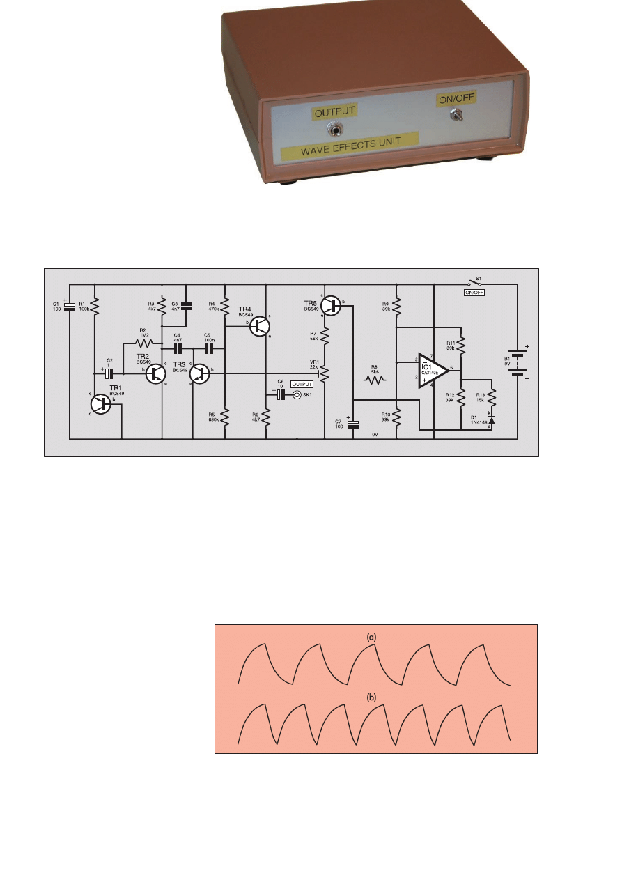
Fig.2. Complete circuit diagram for the Wave Sound Effect unit.
µ
µ
µ
µ
Fig.3. The normal waveform from the oscillator (a), and the waveform produced
with steering diode D1 and resistor R13 included (b).
is discharging, but D1 prevents any current
flow through R13 when C7 is charging.
The rising edge of the waveform is left
intact, but the falling edge is shortened, as
in Fig.3b.
Transistor TR5 operates as an emitter
follower buffer stage at the output of the
oscillator. Preset potentiometer VR1 atten-
uates the output of the oscillator and brings
it into a suitable voltage range to control
transistor TR3. In practice preset VR1 is
adjusted to obtain the most convincing
wave effect.
The current consumption of the circuit is
around 4mA to 5mA, and a PP3 size bat-
tery is therefore adequate as the power
source.
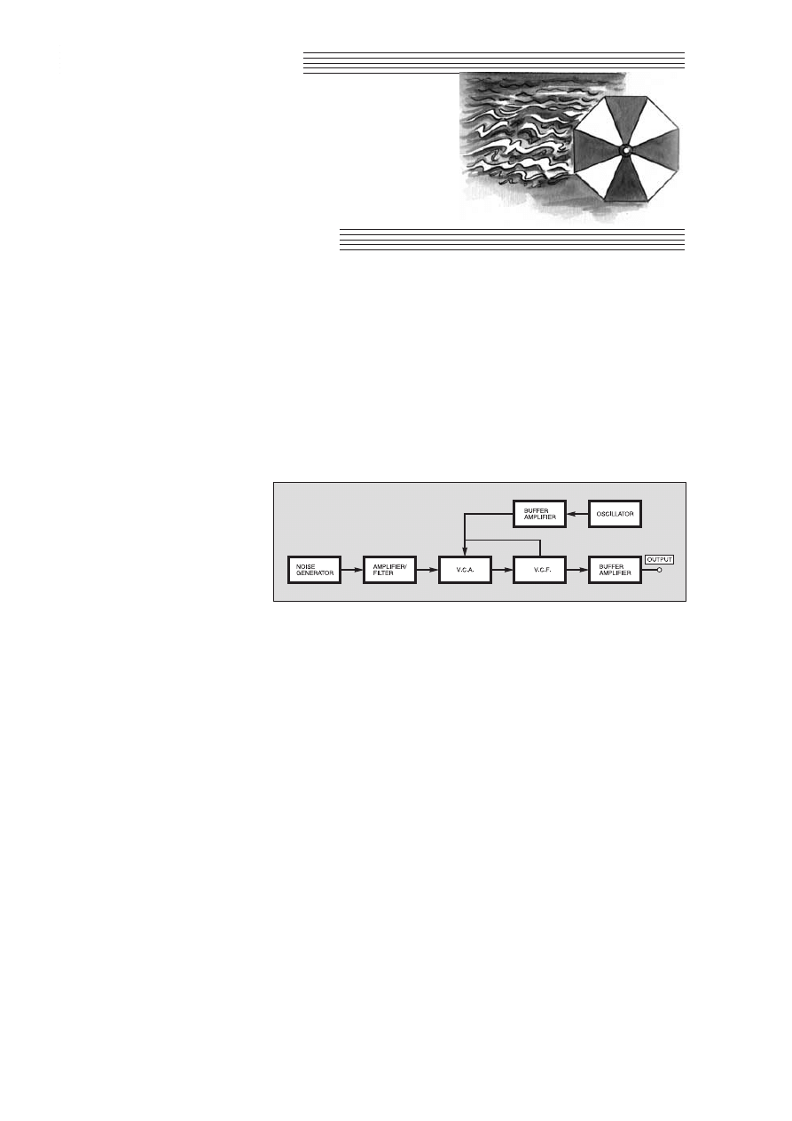
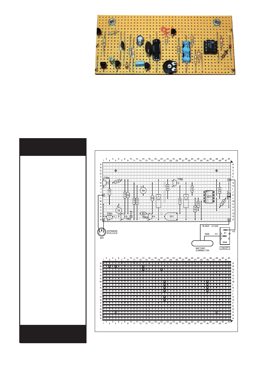
CONSTRUCTION
The Wave Sound Effect stripboard com-
ponent layout is shown in Fig.4, which also
shows the small amount of hard wiring and
details of breaks required in the copper
strips on the underside of the board. The
board measures 42 holes by 19 strips and,
as this is not one of the standard sizes in
which stripboard is sold, it must, therefore,
be cut from a larger piece using a hacksaw
or a junior hacksaw. Cut along rows of
holes and then file any rough edges to a
neat finish.
The breaks in the copper strips can be
made using the special tool, alternatively a
handheld twist drill bit of about 5mm to
5·5mm in diameter does the job quite well.
Either way, make sure that the strips are cut
across their full width and that no hairline
tracks of copper are left. The two mounting
holes are three millimetres in diameter and
will take either 6BA or metric M2·5 bolts.
Next, the components and link-wires
should be added. The CA3140E specified
for IC1 is a PMOS device, which is there-
fore vulnerable to damage from static
charges. The normal handling precautions
should be observed when dealing with this
component, and the most important of these
is to fit it onto the board via an i.c. holder.
Do not fit IC1 into its holder until the
circuit board has been completed and
double-checked for any errors. Try to touch
the pins as little as possible, and keep the
device away from any obvious sources of
static electricity.
In all other respects construction of the
board is perfectly straightforward. The
Resistors
R1
100k
R2
1M2
R3, R6
4k7 (2 off)
R4
470k
R5
680k
R7
56k
R8
5k6
R9, R10,
R11, R12 39k (4 off)
R13
15k
All 0·25W 5% carbon film
Potentiometer
VR1
22k min. enclosed
carbon preset,
horizontal
Capacitors
C1, C7
100
m axial elect.
10V (2 off)
C2
1
m radial elect. 50V
C3, C4
4n7 mylar (2 off)
C5
100n mylar
C6
10
m 25V or 100m 10V
radial elect. (see text)
Semiconductors
D1
1N4148 signal diode
TR1 to TR5 BC549
npn transistor
(5 off)
IC1
CA3140E PMOS op.amp
Miscellaneous
S1
s.p.s.t. min toggle switch
B1
9V battery (PP3 size),
with connector clip
SK1
3·5mm stereo jack
socket (see text)
Stripboard 0·1-inch matrix, size 42 holes
by 19 strips; small or medium size metal
or plastic case; 8-pin d.i.l. holder; multi-
strand connecting wire; solder pins (4
off); solder; fixings, etc.
COMPONENTS
Approx. Cost
Guidance Only
£
£8
8..5
50
0
excluding batt. & case
See
S
SH
HO
OP
P
T
TA
AL
LK
K
p
pa
ag
ge
e
246
Everyday Practical Electronics, April 2001
General layout of components on the completed circuit board.
Fig.4. Wave Sound Effect stripboard component layout, wiring and details of breaks
required in the underside copper tracks.

link-wires can be made from 24 s.w.g.
tinned copper wire or the trimmings from
the leads of the resistors. Fit single-sided
solder pins to the board at the positions
where connections will be made to output
socket SK1, switch S1, and the battery
connector.
Apart from C4, the non-electrolytic
capacitors must have proper leads rather
than pins, and Mylar capacitors are the best
choice. The board was designed for use
with axial lead electrolytic capacitors in
the C1 and C7 positions, but radial lead
components should fit quite well into the
layout. A value of 10
mF is suitable for C6
if the unit is to be used with an amplifier or
a crystal earphone, but a value of 100
mF is
better if the output will be used to drive
headphones.
CASING UP
Most small and medium size cases are
suitable for this project. A small instrument
case is used for the prototype, but a simple
plastic or metal box is perfectly adequate.
The circuit board is mounted inside the
case using 6BA or metric M2·5 bolts,
including short spacers or some extra nuts
between the case and the board. It is prob-
ably best not to use plastic stand-offs, since
most types do not work well with strip-
board. On/off switch S1 and output socket
SK1 are mounted on the front panel.
The best type of socket to use for SK1
depends on the way the unit will be used.
For use with the “Aux” input of a hi-fi sys-
tem a phono socket is the most appropriate.
In fact, the easiest way of handling things
is to connect the output of the board to two
phono sockets. The output of the unit can
then be coupled to both stereo channels of
the hi-fi system using a standard twin
phono lead.
A 3·5mm mono jack socket is needed for
a crystal earphone, and a stereo type is
required for use with medium impedance
headphones, which are the type sold as
replacements for personal stereo systems.
The wiring shown in Fig.4 is correct for a
popular form of 3·5mm stereo jack socket.
As the two phones are wired in series the
common earth tag is left unused, and the
output of the unit is wired to the other two
tags.
ADJUSTMENT
AND USE
With the unit set up for use and preset
VR1 set fully counter-clockwise, there
should be a continuous noise sound at a
fairly low pitch from the headphones or
loudspeakers. If VR1 is tried at various set-
tings in a clockwise direction some sweep-
ing of the pitch and amplitude of the noise
should be produced. You need to be patient
here, because the sweep rate is quite low
and it takes a while for each cycle to be
completed.
Adjusting VR1 is really just a matter of
using trial and error to obtain the best
effect. This means finding a setting that
provides the full sweep range without the
sound holding for too long at either end of
its range, but particularly at the low pitch
end.
There is plenty of scope for experiment-
ing with circuit values in an attempt
to optimise the effect. Here are a few
suggestions:
C3 – A higher value gives an overall
reduction in the pitch of the
sound, and a lower value has the
opposite effect.
C4 – Use a lower value to give a high-
er maximum pitch, or a higher
value for a lower maximum pitch.
C7 – A higher value reduces the fre-
quency of waves, and a lower one
gives an increased wave rate.
R11 – A lower value gives a wider
sweep range, and a higher value
produces a more restricted sweep
range.
R13 – A lower value reduces the time
taken for waves to recede, and a
higher value has the opposite
effect. Changing the value of this
resistor will also produce some
change in the wave rate.
If the signal tends to cut off when the
battery voltage falls slightly due to ageing,
it is probably worth replacing transistor
TR1. Some BC549s have lower breakdown
voltages than others, and one having a low
breakdown potential gives better battery
life.
Incidentally, virtually any small silicon
npn transistor should work in the TR1 posi-
tion of this circuit. The other transistors
can be any high gain silicon npn devices
such as a 2N3704, but note that alternative
devices will mostly have different encapsu-
lations or leadout configurations.
$
Everyday Practical Electronics, April 2001
247
These is plenty of room inside this small instrument case for the battery.
E
EP
PE
E B
BIIN
ND
DE
ER
RS
S
KEEP YOUR MAGAZINES SAFE – RING US NOW!
This ring binder uses a special system to allow the issues to be easily removed and re-inserted without any
damage. A nylon strip slips over each issue and this passes over the four rings in the binder, thus holding the
magazine in place.
The binders are finished in hard-wearing royal blue p.v.c. with the magazine logo in gold on the spine. They
will keep your issues neat and tidy but allow you to remove them for use easily.
The price is £5.95 plus £3.50 post and packing. If you order more than one binder add £1 postage for each
binder after the
initial
£3.50 postage charge (overseas readers the postage is £6.00 each to everywhere except
Australia and Papua New Guinea which costs £10.50 each).
Send your payment in £’s sterling cheque or PO (Overseas readers send £ sterling bank draft, or
cheque drawn on a UK bank or pay by card), to Everyday Practical Electronics,
Allen House, East Borough, Wimborne, Dorset BH21 1PF. Tel: 01202 881749. Fax:
01202 841692.
E-mail: editorial@epemag.wimborne.co.uk.
Web site: http://www.epemag.wimborne.co.uk
We also accept card payments. Mastercard, Visa or Switch (minimum
card order £5). Send your card number and card expiry date plus Switch
Issue No. with your order.
Lateral Thinking
N
OWADAYS
, it is likely that there are
many dormant ideas waiting for a suit-
able application. There are possibly many
other ideas that already have one area in
which they are used, and by using some
lateral thinking they could be used in
another.
One example of this is liquid crystal tech-
nology. Currently l.c.d.s are widely used as
displays, but CRL Opto based in Hayes UK,
a leading supplier of custom shutters and
specialist coatings, has devised a way of
using fast switching ferro-electric liquid
crystal devices to capture a 3-D image in
combination with a single lens camera.
Normally two cameras, or at least two lens-
es are required to capture the two images
that are required for a 3-D image. This new
technology, it is claimed, can be incorporat-
ed easily into a variety of applications where
a 3-D image is required including ordinary
camcorders, more sophisticated television
cameras or endoscopes.
L.C.D. Operation
Unlike many other types of display a liq-
uid crystal display (l.c.d.) operates by
allowing or blocking the light passing
through it. The principle of operation is
based around the polarisation of the light.
The most common type of l.c.d. is
known as the “twisted nematic” display.
Light entering the display first passes
through a polarising filter to ensure that all
the light is of a given polarisation. A sec-
ond polarising filter is placed at the back of
the display, with a polarisation at 90
degrees to the first one. Under these cir-
cumstances no light will pass through the
display because the two polarising filters
have different polarisations, and the dis-
play will appear dark.
The two polarising filters are held a
small distance apart, typically only 10
micrometers. This space is filled with a
substance known as a liquid crystal. A
transparent conducting element is placed
on the inside of each of the filters to give
the required display patterns.
The liquid crystal has the property that it
rotates the polarisation of the light passing
through it. About 40 micrometers is suffi-
cient to give a full 360 degree rotation – 10
micrometers gives 90 degrees. With the
liquid crystal in place the light passes
through the first polarising filter, is rotated
through 90 degrees by the liquid crystal
and is then able to pass through the second
filter which has its line of polarisation at
90 degrees to the first.
However, when a potential is applied
across the liquid crystal it looses its ability
to rotate the polarisation of the light.
Accordingly, when the light reaches the
second filter its polarisation is 90 degrees
out of line with the second filter and can-
not pass through. A dark area is seen. The
area that is affected is dependent upon the
area across which the potential is applied.
Therefore by varying the patterns of the
conductors on the inside of the filters and
which ones have potentials applied across
them, different areas can be made to be
light and dark.
248
Everyday Practical Electronics, April 2001
New Technology
Update
An innovative approach to using liquid
crystal display technology has made it
possible to create 3-D images, reports
Ian Poole.
Operation
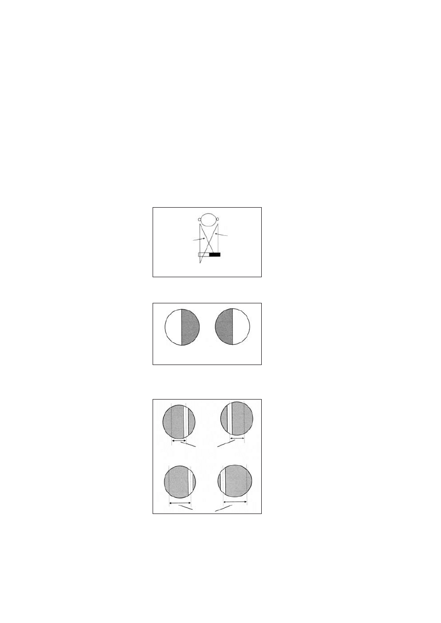
The CRL system operates by having a
two element shutter placed in the iris plane
of the optics so that either a left or right
hand view of an object can be seen. By
blanking off half the liquid crystal screen
or shutter, a left or right hand view of the
image is obtained,see Fig.1.
The shutter can switch from one image
to the other in less than 100 microseconds
enabling switching rates greater than 25Hz
to be achieved making it ideal for many
camera scanning formats. When employed
with an interlaced camera scanning sys-
tem, the shutter has one half open for the
even lines of the frame, and the other half
open for the odd lines. This creates a sim-
ple basic 2-element “stereo’’ shutter, see
Fig.2. The stored composite signal can
then be replayed on a conventional system
and viewed using a similar liquid crystal
shutter system, or through a more conven-
tional system using red/green glasses.
It is possible to alter the stereo separation
(i.e. the stereo depth). This can be achieved
by altering the separation between the two
images. The shutter can employ strips as
shown in Fig.3. By changing the separa-
tion between the two strips, the separation
and hence the stereo depth can be altered.
This is particularly useful when using a
zoom lens to ensure that a realistic
stereo depth is maintained during a zoom
operation.
The problem with using small strips in
the shutter is that the amount of light enter-
ing the camera is reduced. In cases where
light is a problem it is possible for less than
half the shutter to be blanked off.
This does reduce the amount of light but it
gives a greater degree of flexibility to trade
off stereo depth against the amount of light
received. This is very analogous to the trade-
off between aperture and depth of focus in
more traditional cameras.
Summary
This new development shows a particu-
larly innovative approach to using liquid
crystal displays. CRL has taken a well-
known piece of technology and used it in a
totally new way, thereby extending its
application. In doing this it provides a new
method of producing stereo images using
existing equipment technology, but with
the addition of the new shutter, and possi-
bly a small amount of additional electron-
ics to synchronise the shutter.
As costs are relatively low it could be a
particularly attractive proposition for any-
one wanting to produce stereo images.
Further information can be found at:
www.crlopto.com.
Fig.1. How a two element shutter in the
iris plane selects right and left views of
the same object through a single lens.
Fig.2. Simple 2-element stereo shutter.
The shaded area indicates the non-
transmitting region, and the open area
indicates where the shutter is open.
Fig.3. Using multiple vertical strips in
the shutter enables the amount of
stereo depth to be altered to the appli-
cation in hand: (b) shows a greater
stereo depth than (a).
Object
Off axis light from
right of object
2 element shutter
Off axis light from
left of object
Light passes
through
Light blocked
(a) Left part open, right
part closed.
(a) Right part open, left
part closed.
Stereo depth
(a)
Larger
Stereo depth
(b)

BT had 77,000 payphones in 1984, when
the company was privatised. Until recently
BT was adding a hundred boxes a year.
The current number is 141,000, but there
has been no increase since 1999.
BT justifies this by saying that over the
same two year period payphone use has
declined by 37 per cent.
For most people with a cellphone, it is
cheaper to use it than feed a payphone.
The minimum payphone charge went up in
October 2000 from 10p to 20p, with calls
to anywhere in the UK costing a flat fee of
11p a minute. Payphones do not give
change for unused payment.
Oftel wants BT to keep providing boxes
in rural areas where a public service is
needed, and cellphone cover is erratic. BT
insists that it will do this.
BT also points to the fact that there are
now 600 multi-media payphones, each
with a 12-inch touch sensitive colour
screen. Until June 14 these can be used to
access the Internet or send E-mail for free.
But after June 14 the calls will be charge-
able, probably at around the same rate as a
speech call, and possibly with a few min-
utes free in return for viewing adverts.
So far the 600 multi-phones are in “safe”
locations, in shopping centres, railway and
tube stations, airports and motorway ser-
vices. Vandalism is less likely at these
sites, than in remote rural areas.
The biggest risk may come from
“scratchiti”, the word coined in the USA
to describe vandalism by the deliberate
scratching of glass windows with dia-
monds and pumice stone.
BT says it sees the move into multi-
media kiosks as helping the Government
honour its pledge of offering everyone on-
line access by 2005.
CHILD’S PLAY
MAPLIN have launched a new range of
kits aimed at helping children to under-
stand the basic principles of electronics.
The Experilab kits are said to be ideal
for children aged nine and above. No sol-
dering or previous electronic knowledge is
required and the inexpensive packs
include all the necessary components and
easy to follow instructions. The kits are
available from Maplin’s 59 nationwide
stores and via Maplin’s web site.
For more information contact Maplin
Electronics, Dept EPE, Valley Road,
Wombwell, Barnsley S73 0BS. Tel: 01226
751155. Fax:
01226 340167. Web:
www.maplin.co.uk.
Greenweld Fires
Enthusiasm
GREENWELD continue to rise, phoenix-
fashion, from the crisis the company under-
went nearly two years ago. Their latest
bargains catalogue has increased to 48 pages
and is crammed with items that any self-
respecting electronics hobbyist loves brows-
ing through in search of those that make our
hobby even more interesting and worthwhile.
From modellers’ tools and equipment, to
electronic components and superb kits,
Greenweld say that with their great value
prices and mail order service, there’s
something in the catalogue for everyone.
Check it out for yourself:
Greenweld Ltd, Dept EPE, PO Box 144,
Hoddesdon EN11 0ZG. Tel: 01277
811042. Fax: 01277 812419. E-mail: ser-
vice@greenweld.co.uk.
WCN Supplies Catalogue
ISSUE 7 of WCN Supplies’ 24-page A4
catalogue includes a broad variety of items
that electronics enthusiasts will find
appealing. Principally, they are of the
“workshop accessories” type, including
meters, batteries, computer cables, con-
nectors, power supplies, tools etc.
The catalogue appears to be a useful
source of supply and can be obtained from
WCN Supplies, The Old Grain Store, 62
Rumbridge Street, Totton, Southampton
SO40 9DS. Tel/fax: 023 8066 0700.
N
Ne
ew
ws
s .. .. ..
A roundup of the latest Everyday
News from the world of
electronics
B
BT
T R
RE
EP
PO
OR
RT
TS
S R
RE
ED
DU
UC
CT
TIIO
ON
N IIN
N
P
PH
HO
ON
NE
E K
KIIO
OS
SK
K U
US
SE
E
It’s all down to the mobile, reports Barry Fox
Everyday Practical Electronics, April 2001
251
CHIP-ON-GLASS L.C.D. MODULES
NOW that you’ve been inspired
to investigate graphics l.c.d.s
(Feb ’01), why not have a
browse of Glyn’s web site for
information about their new
Chip-On-Glass L.C.D. Display
modules, from Seiko’s Vitrium
series? COG modules are said
to be ideal for portable applica-
tions, offering high density per-
formance in the smallest
possible package.
Glyn tell us that the modules
“eliminate the need for printed
circuit boards . . . are mounted
directly on glass, achieving
greatly improved optical perfor-
mance and reliability”.
Glyn’s web site is at
www.glyn.com.
T
HE
widespread use of cellphones is providing BT with the opportunity to cut
back on the costly installation and maintenance of payphones – as required
under BT’s licence to operate.
PROTEUS
LABCENTER, one of Britain’s leading
CAD developers, has released Proteus
VSM. This latest addition to Labcenter’s
range is described as a revolutionary sys-
tem level simulation product, and is the
first in the industry.
VSM simulates microcontroller based
designs, including the CPU, and all asso-
ciated electronics at near real-time speeds.
It includes animated component models.
For example, l.e.d./l.c.d. displays, switch-
es, keypads and virtual instruments,
allowing the user to interact with the
microprocessor software as if it were a
physical prototype. It supports PICs, 8051
and 68HC11 processors.
The system includes an integrated
debugger. It is also compatible with the
Keil C51 development system.
For more information contact Labcenter
Electronics, Dept EPE, 53-55 Main Street,
Grassington, N.Yorks BD23 5AA. Tel:
01756 753440. Fax: 01756 752857.
E-mail: info@labcenter.co.uk.
Web: www.labcenter.co.uk.

Rabbit’s Demise
Barry Fox
HONG Kong telecoms giant Hutchison
ran the ill-fated Rabbit second generation
cordless phone system, before replacing it
with the Orange cellphone network.
Hutchison also ran a paging system which
took on the Orange name. This still has
30,000 customers, of which 5,000 are con-
sumers. But most people now use cell-
phones and SMS, short messaging service,
instead of pagers. So Orange is shutting
down the paging service on 30 June.
Customers will be given sweeteners,
such as free Orange phones. “Our paging
business has been overtaken by develop-
ments in technology”, says Orange.
In the USA paging is still popular
because cellphone users must pay for
incoming calls. Cost conscious consumers
use a pager along with a cellphone, taking
incoming messages free by pager and
returning selected calls by cellphone.
Paging also remains the only safe way to
communicate in hospitals, because the
pager is just receiving, not transmitting.
Paging signals, at lower frequencies and
lower data rate than cell phones, also pen-
etrate deeper into multi-level concrete
buildings.
OOPS-OOPIC!
LAST month we misinterpreted Total
Robots’ press release about their OOPic
object-orientated programmable integrat-
ed circuit. The design is based on PIC
microcontrollers – it uses the PIC16C74.
We apologise for this error. For more
information browse web site www.total-
robots.co.uk or phone 01372 741954.
Atmel Acquires Siemens
ATMEL have reached an agreement to
acquire Siemens’ North Tyneside plant and
will resume semiconductor fabrication.
This should lead to the creation of between
1000 and 1500 high quality direct jobs
within two to three years, with additional
spin-off employment as well.
Siemens closed their plant two years ago
when the world semiconductor market col-
lapsed. You may recall that Fujitsu also
closed their semiconductor plant in
County Durham at about the same time.
American headquartered Atmel designs,
manufactures and markets advanced logic,
mixed signal, non-volatile memory and
RF semiconductors. The company’s
arrival is excellent news for the North East
region of the UK, and has been assisted by
a £27.8m Government grant.
Educating Quasar
QUASAR Electronics in their latest
newsletter remind tutors and teachers that
generous discounts are available for bulk
purchases of their electronics kits.
Schools, colleges and universities are
granted automatic 30-day account facili-
ties and discounts of up to 35 per cent.
Of course Quasars kits and other elec-
tronics products are of interest to anyone,
so get hold of their catalogue and onto the
mailing list for regular updates!
Quasar Electronics Ltd., Dept EPE, Unit
14, Sunningdale, Bishops Stortford, Herts
CM23 2PA. Tel: 01279 306504. Fa: 07092
203496. E-mail: epesales@quasarelec-
tronics.com. Web: www.quasarelectron-
ics.com.
CHINA’S DVD
CHALLENGE
Barry Fox
CHINESE and Taiwanese electronics
companies are under attack. They have
been undercutting Western suppliers, by
selling DVD players for under $100. Now,
the 6C Group (Hitachi, JVC, Matsushita,
Mitsubishi, Toshiba and Warner) are using
their pooled patents to seek a four per cent
royalty on hardware. Another group,
Philips, Pioneer and Sony separately claim
3·5 per cent. Dolby claims another slice
for digital surround, Macrovision for copy
protection, the MPEG Licensing Authority
for compression. Discovision and
Thomson are still claiming royalties on old
optical disc patents. The total claim is
around 10 per cent of the manufacturing
cost for a player.
During meetings in Beijing and Taipei
China with Toshiba’s Koji Hase, Chairman
of the DVD Forum, the Chinese sprang a
surprise. They claimed that the Chinese
government will set its own modified
DVD standard called Advanced Video
Disc, and will claim its own royalties if
foreign manufacturers try to import AVD
players into China.
This is a re-run of the situation when
China developed the Super Video CD sys-
tem to rival the Video CD format devel-
oped and patented by JVC, Matsushita,
Philips and Sony.
The AVD idea looks suspiciously like an
attempt at trading one set of royalties off
against another, but it overlooks the basic
fact that AVD will still have to use the
basic DVD technology patents.
The many companies in Europe and the
USA which import DVD players from
China, for branding with Western names,
may now find themselves legally liable for
royalties unpaid by their Far Eastern
suppliers.
Mobile Phones
Risk Report
THE National Radiological Protection
Board (NRPB) has advised us that the
results of a study in the USA in respect of
brain tumours and the use of mobile
phones have been released at
www.nejm.org/content/inskip/1.asp.
The study does not show an association
between them. NRPB state that further
study is required.
The NRPB also tells us that it has pub-
lished a broadsheet, Medical Radiation,
as part of its At-a-Glance series. It is
intended for readers with little or no
knowledge of the subject and explains
how radiation is used to diagnose and
treat illnesses. It relies heavily on illus-
trations and captions as a means of com-
municating information.
Individual copies of Medical Radiation
are free of charge and can be obtained
direct from the NRPB Information Office.
For more information contact: NRPB,
Chilton, Didcot, Oxon OX11 0RQ. Tel:
01235 822744. Fax: 01235 822746.
E-mail: information@nrpb.org.uk.
Web: www.nrpb.org.uk.
252
Everyday Practical Electronics, April 2001
COLE-PARMER have released their 2001-2002 catalogue, which they describe as “the
best scientific and technical catalogue”. It contains over 2000 full colour pages with more
than 40,000 innovative products. The general headings highlighted include
Manufacturing, Semiconductor, Chemical, Industrial, Environment, Education,
Pharmaceutical, R&D, to mention just a few. It’s the sort of catalogue which can be invalu-
able to any hobbyist with an enterprising mind and fertile imagination.
For more information contact Cole-Parmer Instrument Company Ltd., Dept EPE, Unit
3, River Brent Business Park, Trumper’s Way, Hanwell, London W7 2QA. Tel: 0500
345300.
Fax:
020 8574 7543.
E-mail:
sales@coleparmer.co.uk.
Web:
www.coleparmer.com.
S
SC
CIIE
EN
NC
CE
E C
CA
AT
TA
AL
LO
OG
GU
UE
E
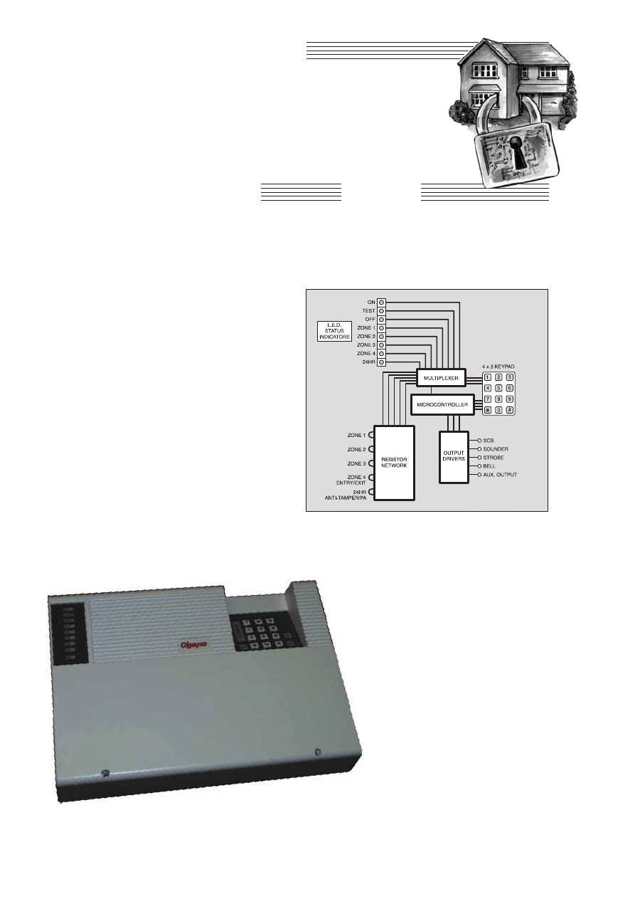
CCoonnssttrruuccttiioonnaall PPrroojjeecctt
T
HIS
Intruder Alarm Control Panel
system is based on the Motorola
EP520M security microcontroller.
The EP520M is a robust device having
its origins at the heart of an automobile
engine management system – a hostile
environment for any microcontroller to
work in. Now masked as an alarm
controller, the device operates in high
electrical noise and RFI environments, dis-
playing a high degree of immunity to such
hazards.
These devices are used in control panels
throughout the UK and Europe, and are
reputed to be completely reliable and free
from false alarming.
The EP520M’s extensive features
include four detection zones, with one pro-
grammable as an Entry-Exit Delay zone,
plus a 24-hour monitor for anti-tamper
devices and Panic Attack (PA) use.
Normally-closed (NC) and normally-open
(NO) detectors can be used on all zones.
The main features of the system are listed
in the Specifications panel.
It can be seen from the block diagram in
Fig.1 that the EP520M requires only the
addition of a simple keypad and a minimum
of readily available components. The circuit
has been designed to comply with the
installation require-
ments of British
Standards BS4737
Part 1.
Despite the sophis-
tication of the system,
the alarm is extreme-
ly simple to construct
and operate.
ZONES
Zones 1, 2 and 3 are
all “immediate” and
violation (opening) of
the normally-closed
(NC) circuit causes an
alarm activation. Zones
1 to 4 are positive
polarity and if the NC
loop is shorted to the
negative 24-hour PA
anti-tamper circuit NC
loop, then a full alarm
activation results, and
is indicated on the asso-
ciated zone l.e.d.
Consequently, normally-
open devices can also be
used to activate the
zones.
Zone 4 is used for timed entry-exit con-
trol and is programmable to give a delay of
between 0 and 255 seconds, in order to
enter and leave the alarmed area.
Zones 1 to 4 are for use with any stan-
dard type of normally-closed intruder
detector, such as magnetic contact switch-
es, pressure pads, passive infra-red (PIR)
sensors etc.
Zone 5 comprises a normally-closed
24-hour Anti-Tamper PA loop circuit
which causes a full alarm activation if
violated. Anti-tamper switches to protect
the detection and external sounder
devices are wired to this circuit. Panic
Attack button switches can also be wired
to it.
You can activate the alarm when it is
switched off by pressing the PA button. This
a very useful security feature when answer-
ing a door with a PA button sited nearby.
AUDIO-VISUAL
ALARMS
The bell output is the main alarm driver
and direct current (d.c.) sounders requiring
up to about 1A can be connected to it.
INTRUDER ALARM
CONTROL PANEL
Microcontrolled security designed to meet British
Standards specification BS4737.
254
Everyday Practical Electronics, April 2001
JOHN GRIFFITHS
Fig.1. System block diagram.
Part One

An optional 12V d.c. 250mA Xenon
strobe may be connected to the Strobe
terminals. In the event of an alarm acti-
vation the strobe will operate. If the
alarm carries on until the Auto Reset
period is reached, the alarm sounder will
silence but the strobe will carry on oper-
ating. This gives an indication to the user
returning to the property that something
may be amiss and to proceed with
caution.
When the alarm is activated, a high and
low level 1kHz tone output is generated via
an internal loudspeaker. In normal opera-
tion, the output level is restricted and gives
the test tones and keypad response.
However, when a full alarm condition
occurs, the full output power is delivered to
the speaker.
CIRCUIT
DESCRIPTION
The circuit diagram for the Intruder
Alarm Control Panel is shown in Fig.2.
The EP520M microcontroller is desig-
nated as IC1. It has its own internal clock
oscillator whose precise frequency can be
set by resistor R1 and preset potentiometer
VR1.
Zone 1 to Zone 4 connections are biased
on one side to the 12V line via resistors in
module RM5, and on the other side to the
0V line via resistors in module RM4.
Series resistors in module RM3 feed from
the zone loop to the 8-way multiplexer IC2.
On the same inputs the resistors in RM2 act
as potential dividers in conjunction with
those in RM3.
This resistor combination holds the
inputs to IC2 at around 4V when the zone
loop is in circuit. When the circuit is bro-
ken, the inputs are held at 0V.
Zone 5 is biased from the 12V line in the
same way, using discrete resistors R12,
R13 and R14. However, the 0V connection
is made via anti-tamper microswitch S1. In
this path an optional link (SCB) can be
broken and an external anti-tamper switch
connected as well.
4 ZONES 4 × 12hr positive polarity detection circuits for NO
and NC devices
24HR CIRCUIT 1 × 24hr anti-tamper circuit for NC devices
NVM Non-volatile memory to retain all programmable data
during power failure
AUTO RESET Automatic resetting of the alarm after preset
period
BELL SHUT OFF Automatic silencing of alarm after a preset
period (selectable)
AUDIBLE WALK TEST Tests all detection zones prior to
setting system
LAST TO ALARM MEMORY Shows zone that was violated
NIGHT SET Sets system without the Entry/Exit delay time
OMIT ZONE Allows any zone except 24hr to be omitted
LATCHING STROBE Strobe carries on after Auto Reset or bell
switch off
SWITCHED +12V OUTPUT For latching PIRs and other
control purposes
SCB INPUT Negative control for self-contained bell
STATUS DISPLAY System status shown on 8 l.e.d. indicators
INTERNAL/EXTERNAL SIREN High and low level siren
output to 4
W to 16W speaker
1·2A PSU For charging up to 7AH back-up battery
FINAL DOOR SET OPTION Sets alarm when the Exit door is
closed
ENGINEER’S CODE Used to change factory defaults
USER CODE Used to Set and Unset Alarm
12 BUTTON KEYPAD To Set and Unset the alarm and
program variables
WALK THROUGH Allows user to violate zone when exiting
and entering
PROGRAMMABLE FEATURES
Default
EXIT TIME
0 to 255 secs
20 secs
ENTRY TIME
0 to 255 secs
20 secs
AUTO RESET
1 to 99 mins
20 mins
BELL SHUT OFF
1 to 99 mins
Off
ACCESS CODE
0000 to 9999
1234
ENGINEER’S CODE
0000 to 9999
54321
WALK THROUGH
Zone 1
Off
TEST TONE
All zones
On
FINAL DOOR CANCEL Zone 4
Off
EXIT TONE ON
Zone 4
On
ENTRY TONE OFF
Zone 4
On
NOTE: When actually entering the engineer’s code in normal
use prefix the 4-digit code with the number 5 before the code, e.g.
an engineer’s code of 4321 entered in the program mode would be
entered as 54321 for engineer’s access.
SPECIFICATIONS
MAIN BOARD
Resistors
R1
27k
R2, R3,
R5 to R7 10k (5 off)
R4
150
W
R8
68
W 1W
R9 to R11
3k9 (3 off)
R12
2k7
R13
100k
R14
56k
R15
1k
All 0·25W 5% metal film except R12.
Resistor modules
RM1
8 × 1k common 9-pin
RM2
4 × 47k individual 8-pin
RM3
4 × 100k individual 8-pin
RM4
4 × 10k individual 8-pin
RM5
4 × 1k individual 8-pin
All single-in-line resistor modules
Potentiometers
VR1
10k preset, min. horiz,
5mm
VR2
1k preset, min. horiz,
5mm
Capacitors
C1
10
m tantalum, 16V
C2
2200
m axial elect. 25V
C3 to C6,
C8 to C14 100n ceramic disk (11 off)
C7
1
m axial elect. 25V
Semiconductors
D1 to D4
D8 to D10
D22
1N4148 signal diode
(8 off)
D5, D6
8V2 Zener diode (2 off)
D7, D11,
D12
1N4001 rectifier diode
(3 off)
D13 to D21 red l.e.d. (9 off)
TR1
BC307
npn transistor
TR2, TR4
TIP120
npn Darlington
transistor
COMPONENTS
See
S
SH
HO
OP
P
T
TA
AL
LK
K
p
pa
ag
ge
e
TR3
TIP125
pnp Darlington
transistor
IC1
EP520M alarm system
microcontroller
(Motorola)
IC2
74HS151 8-way
multiplexer
IC3
93C06 non-volatile
memory
IC4
7812 +12V 1A voltage
regulator
IC5
7805 +5V 1A voltage
regulator
REC1
W05 50V 1A bridge
rectifier
Miscellaneous
TB1, TB2
2-way screw terminal
block, 5mm pin
spacing, p.c.b.
mounting (2 off)
TB3, TB4
10-way screw terminal
block, 5mm pin
spacing, p.c.b.
mounting (2 off)
FS1
1A fuse, 20mm slow blow
FS2, FS3
500mA fuse, 20mm, slow
blow (2 off)
LS1
loudspeaker, 12W 8
W
mylar
S1
s.p. push-to-make switch,
p.c.b. mounting, spring
activated (Alps)
T1
mains transformer, 12V
a.c. 1A secondary
Printed circuit board, available from the
EPE PCB Service, code 297 (Main); 3 × 4
matrixed keypad, data entry type; fuse
clip, 20mm, p.c.b. mounting (3 off); small
metal heatsink for IC5 (see text); 8-way
pin-header, 0·1in pitch, straight; 8-way
pin-header connector, 0·1in pitch, straight
(2-off); 7-way cable, thin guage, 30mm
long approx; spade connectors for bat-
tery, 5/16in (2 off); 8-pin d.i.l. socket; 16-
pin d.i.l. socket; 28-pin d.i.l. socket; 6BA
nuts and bolts; plastic case (see
Shoptalk); solder, etc.
Approx. Cost
Guidance Only
£
£2
25
5
excluding case
Everyday Practical Electronics, April 2001
255
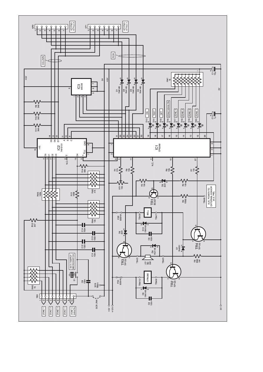
Fig.2. Circuit diagram for the main control unit.
256
Everyday Practical Electronics, April 2001
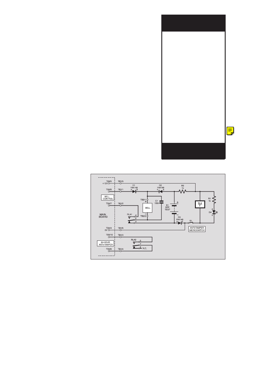
This arrangement holds the Zone 5 input
to the multiplexer normally at 0V, going
high if the circuit is broken via the anti-
tamper or PA switches.
The multiplexer’s zone selection is con-
trolled via its ABC inputs by microcon-
troller IC1, with the selected path routed
back to IC1 via output Y.
FALSE TRIGGERING
PROTECTION
Loop resistance of up to one kilohm
(1k
9 is permissible on the zone circuits. In
practice, though, you would find this would
represent several kilometres of wiring. In
reality, in a normal domestic alarm installa-
tion, the loop resistance would rarely exceed
several ohms, representing a loop current
flow in the order of 1mA, giving good pro-
tection against induced transients.
Additional protection from false trigger-
ing on the detection loops is provided by the
resident software, which polls the zones and
looks for a period of intrusion detection of
not less than 200ms. It then times the period
during which the circuit is detecting. If after
one second the input is still positive, an
alarm condition is validated.
KEYPAD MONITORING
A standard 12-switch data-entry keypad
is also monitored by IC1 via multiplexer
IC2. The keypad has one set of its matrixed
lines (Column) connected to the multi-
plexer. These are biased high by resistors
R9 to R11. The other set of matrixed lines
from the keypad (Row) are routed to IC1
via diodes D1 to D4.
The keyboard is strobed and key
debouncing software routines ensure
reliable operation.
Originally the author intended for a
choice of two keypad pinout styles to be
available, with connections via the pin-
header terminals marked as KP1 and KP2.
However, only the data-entry keypad style
(see later) suiting connector KP1 is
recommended.
ALARM INDICATORS
A further eight outputs from IC1 control
the status-indicating l.e.d.s D13 to D20, via
current limiting 1k
9 resistors in module
RM1. The l.e.d.s show the violated zone(s)
and also the On, Off and Test mode
conditions.
Other IC1 outputs control the internal
loudspeaker (LS1), plus the external strobe
and bell lines, buffered by npn Darlington
transistors TR2, TR3 and TR4.
The microcontroller output that turns on
l.e.d. D13 (Power On) also turns on tran-
sistor TR1 via resistor R2 and voltage lim-
iting Zener diode D5. The transistor routes
12V d.c. to external devices such as passive
infra-red detectors. The current supplied is
limited by resistor R4.
The circuit is arranged so that in Entry,
Exit and Test modes, the loudspeaker only
emits a low level audio tone. An audio fre-
quency generated by IC1 controls TR3 via
R6, and so activating the speaker but limit-
ing its current flow by the inclusion of
resistor R8.
In a full alarm condition, transistor TR4
is also turned on, not only activating the
bell but also sinking current from LS1 via
diode D7. The speaker thus emits a high
level tone, which serves in place of an
internal siren.
NO MEMORY LOSS
The third integrated circuit, IC3, is a
non-volatile memory (NVM) which is used
by the microcontroller to store the keypad
and zone status settings, plus the Access
and Engineer’s pass-codes.
In the event of a complete power failure,
the variables are not lost and when the
power is restored the original codes are still
available, so the system cannot be compro-
mised under such conditions.
EXTERNAL BELL UNIT
Whilst the main circuit can directly con-
trol an external bell, the security of the bell
itself would be compromised – an intruder
could cut the power to it.
To ensure that your alarm installation is
really secure and complies with the instal-
lation requirements of BS4737, it is recom-
mended that a Self Actuating Bell module
(SAB) is fitted. This is intended to thwart
the alarm being silenced in the event that
an intruder removes the power from the
system. It is a bit like an alarm on the
alarm, so to speak.
Bear in mind that any intruder system
that can be disarmed by removing the
power source is as good as useless.
A secondary control unit is thus provid-
ed for inclusion with the external bell hous-
ing. It allows the bell to be switched on by
the main system but it also includes its own
battery and anti-tamper circuit, causing the
bell to operate if the bell enclosure is inter-
fered with. The circuit diagram is given in
Fig.3.
Power to the bell unit is jointly from the
main controller and from the bell battery
(B1 in Fig.3). This powers relay RLA, in
which condition the bell is turned off by
the relay contacts, RLA1. If the main
power fails, the bell battery takes over, still
activating the relay. Light emitting diode
D4 indicates when the power is present
across the relay coil.
An anti-tamper microswitch (S1) is
included in the bell controller housing. If
this normally-closed circuit is broken, the
bell will sound, even if the bell battery is
the only source of power.
The relay also controls the circuit from
the main unit’s anti-tamper detection. If the
bell is interfered with, the main circuit
responds, causing the indoor loudspeaker
to sound at full volume.
It is strongly recommended that the bell
circuit is used in order to provide the pro-
tection required under BS4737.
When fitting the SAB battery, it is sug-
gested that a normal 250mA NiCad pack is
used. The amp-hour endurance of this bat-
tery size is not unduly long so that, in the
event that the main power to the control
panel fails for legitimate reasons, the
EXTERNAL BELL UNIT
Resistors
R1, R2
1k, 0·25W
5%
carbon
film
(2 off)
Capacitor
C1
100n ceramic disk
Semiconductors
D1 to D3
1N4148 signal diode
(3 off)
D4
red l.e.d.
Miscellaneous
RLA
2-pole changeover relay,
12V coil, 24V 1A
contacts, p.c.b.
mounting
TB1
6-way screw terminal
block, 5mm pin
spacing, p.c.b.
mounting
TB2
2-way screw terminal
block, 5mm pin
spacing, p.c.b.
mounting
Printed circuit board, available from
the
EPE PCB Service, code 298
(Ancilliary); bell/siren to suit (see text).
COMPONENTS
See
S
SH
HO
OP
P
T
TA
AL
LK
K
p
pa
ag
ge
e
Approx. Cost
Guidance Only
£
£9
9
excluding case.
Fig.3. Circuit diagram for the external bell unit.
Everyday Practical Electronics, April 2001
257
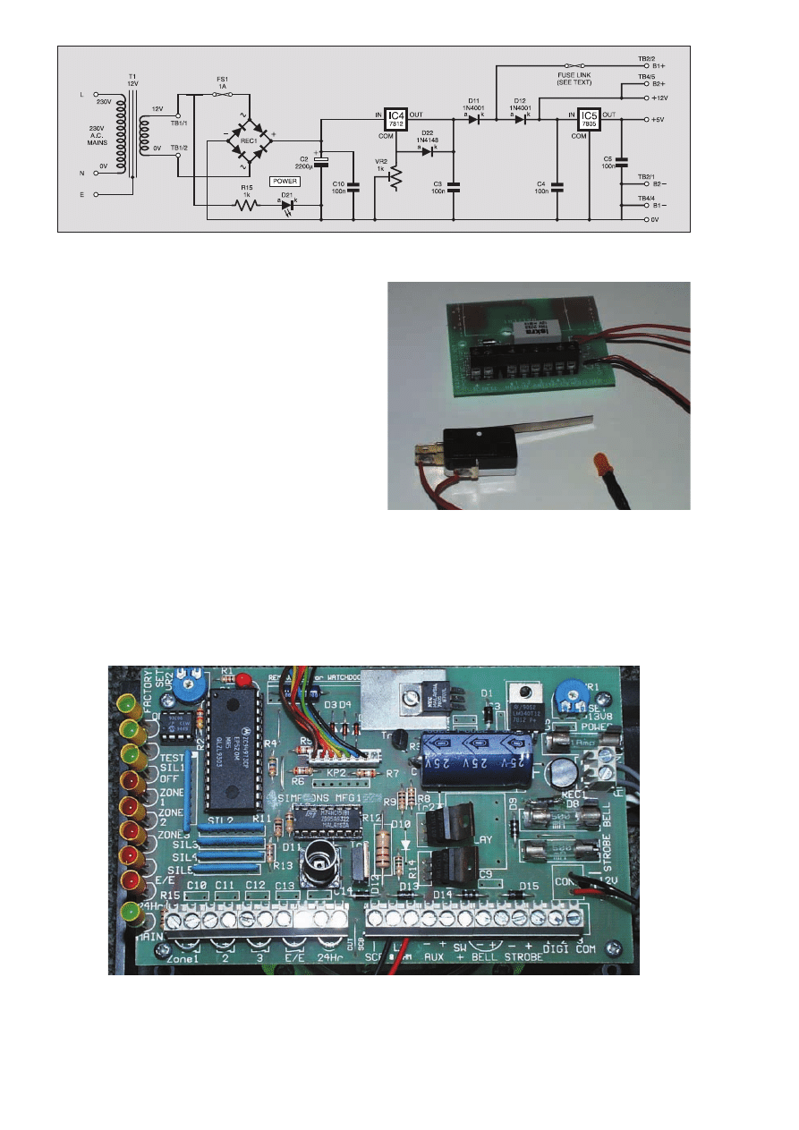
258
Everyday Practical Electronics, April 2001
Fig.4. Circuit diagram for the power supply.
Component layout on the prototype main alarm printed circuit board. Note that the component numbering is different to the
published design and that some components are not shown.
sounder will not operate for more than 40
minutes maximum.
The easiest configuration is to use 6-
core cable between the panel and the SAB,
which should be enclosed in the external
bell box.
POWER SUPPLY
The system is principally mains pow-
ered, but has additional twin-battery back-
up facilities, for which 12V sealed lead
acid batteries rated up to 7AH are recom-
mended. In the event of the mains supply
failing, the battery back-up takes over.
Power requirements for the alarm con-
trol panel are 12V at 1A and 5V regulated
at up to 1A maximum. The main require-
ment of the 12V supply is to drive the
sounders and strobes.
Referring to Fig.4, the power supply
includes transformer T1, bridge rectifier
REC1, smoothing capacitor C2. Fuse FS1
protects the system in the event of a power
output short-circuit.
The rectified output voltage is regulated
at 12V by IC4, which has a maximum out-
put current rating of 1A. The output from
IC4 is also connected to another voltage
regulator, IC5. This provides +5V to IC1,
IC2 and IC3.
Both back-up batteries, B1 and B2, are
kept trickle-charged
via diodes D11 and
D12. Preset poten-
tiometer VR2 allows
the correct charging
voltage to the princi-
pal battery, B1, to be
set at 13·85V, as rec-
ommended by the
manufacturers.
On the printed cir-
cuit board, track feed-
ing to the connector
for B1 is deliberately
“thinned”. This acts as
a fusible link in the
event of a catastrophic
short circuit within the
system, as might be
caused by a malicious
intruder.
The Auxiliary 12V
D.C. output normally
services the PIRs and other detectors
used in the system. Typical current
requirements of such devices are in the
region of about 20mA per unit.
This alarm unit is mains powered and
its construction and testing should only
be undertaken by those who fully
understand what they are doing.
Extension bell unit printed circuit board and anti-tamper
microswitch.
There are two printed circuit boards for
the system, the main control board, and
that for the additional bell control unit.
Both boards are available, as a pair, from
the EPE PCB Service, codes 297 (Main)
and 298 (Bell).
Next Month: Full constructional
details, testing and setting-up.
*

PLEASE “C” TO IT!
Dear EPE,
In your reply to Alan Bradley’s letter in
Readout Feb ’01, you asked for readers
thoughts on the C programming language. I
would definitely be interested to see some of
the software in the magazine written in C. As
an electronics student I have to learn C for my
course, but I had already been using the lan-
guage for several years previously. My only
other (limited) experience is with BASIC
(GWBASIC, QBASIC, etc.) and I found the
change to using C a huge improvement.
Ben Heggs, via the Net
Thanks Ben, we’ll keep it mind.
However, I’ve been giving further thought to
programming languages in general. I understand
that C (and its derivatives) is not necessarily the
best way forward.
For some time Object Orientated program-
ming has become increasingly important to pro-
fessional software designers and I believe that
they regard C as being a “procedural” language
which can lead to different techniques being
employed to achieve the same end. In this context
it appears that Object driven programs have
greater long term “stability” in that Objects are
unique, designed for only one method of use, and
so programmers can more readily understand
what code structures are meant to do, irrespec-
tive of who wrote them. In effect, it appears that
they are “black boxes” which perform a single
dedicated task, with just one access point.
Whilst such matters may not be of immediate
concern to EPE readers, it is something that I
think should be considered as we progress ever
onwards into more sophisticated programming
languages. I appreciate that readers who have
only just grasped one language, such as PIC or
QuickBASIC or Visual Basic, may be reluctant to
climb the learning curve of yet another, perhaps
I should now open up the discussion to include
not only C, but also Object Orientated languages
as well. So let’s be hearing from all who know
about such things (which I do not, as yet).
GRAPHICS L.C.D.S
Dear EPE,
When I read your Using Graphics Liquid
Crystal Displays (Feb ’01) I thought that the fol-
lowing Web addresses might be of relevant inter-
est to your readers:
http://ourworld.compuserve.com/home-
pages/steve_lawther/t6963C.htm
http://www.digisys.net/timeline/lcd.html
http://www.citilink.com/~jsampson/lcdin-
http://www.apollodisplays.com/apollofra-
Prof. Dr Eugenio Martin Cuenca,
Universidad de Granada, Spain
Thank you very much, there appears to be
some most interesting material available. I wish
I had known about it before I started delving into
graphics l.c.d.s!
ALFAC TAPES WANTED
Dear EPE,
I am 66 years old, disabled and cannot draw
circuit plans. However, I found that by using
Alfac precision tapes, circles and i.c. transfer
pads I could manage to do a circuit for etch-
ing. Now I find that I can no longer obtain
them and may have to give up my electronics
hobby, which is the only thing I seem to live
for now.
As a last resort I thought I would write to see
if you could help, or could it be possible to ask if
any readers had any they no longer use. If so,
would they kindly think of me. I used to buy
them from Maplin but they have discontinued
selling them and cannot provide me with Alfac’s
address.
Please, I desperately need help!
John E. Horton, Deal, Kent
Editor Mike received John’s plea for help and
looked into it. He replied directly saying that this
is a problem which we are unable to find a solu-
tion to. He did a search on the Web and could not
find a UK supplier of Alfac products.
Unfortunately these items are simply no longer
in use in industry. Can any readers help John?
UFOs AND AURORAS
Dear EPE,
I read with interest,
the UFO
Detector/Recorder (Jan ’01). In particular, the
ingenuity of Raymond Haigh’s chart recorder is
inspiring. I built something similar ten years ago
for my father, not for detecting UFOs, but for
early warning of auroras and the subsequent
enhancement of h.f. and r.f. propagation, we’re
both radio hams.
The original idea for the detector came from
an article in an astronomical magazine. It
showed a powerful magnet suspended in a jam-
jar full of oil, to slug the movement, and a lin-
ear Hall device to detect the tiny perturbations.
The jamjar detector was installed in the attic
and detected the presence or absence of my car
on the drive 50 feet away, seeing perturbations
of the Earth’s magnetic field proved to be easy
too.
Then came the difficult bit, how do we record
the output? A visit to a radio rally provided an
old X/t recorder for £5. It just needed restringing.
Several yards of fishing line later and exhaustion
of my vocabulary of swearwords, I managed to
restring it. Rolls of chart were expensive but the
results were worth it. So, to the point of this mis-
sive. Hard copy recording of analogue events is
hard work. What is needed is a cheap and easy
method.
Most people these days use a computer and
printer. Some people have bought new colour
printers and failed to sell their dot matrix print-
ers, they’re in their box in the loft. A PIC-based
analogue to Centronics “box” would be very
nice! Z-fold paper for week-long recording, very
cheap A4 for shorter periods. One, two or three
inputs and variable “chart” speed? Date stamp?
X/t grid? Have a think boffins, it’ll make a good
project.
Andy Daw, G1DSF, Stone, Staffs
Seems a feasible idea, Andy, and one which I
believe I can achieve. Watch EPE!
R
RE
EA
AD
DO
OU
UT
T
J
Jo
oh
hn
n
B
Be
ec
ck
ke
er
r
a
ad
dd
dr
re
es
ss
se
es
s
s
so
om
me
e
o
of
f
t
th
he
e
g
ge
en
ne
er
ra
all
p
po
oiin
nt
ts
s
r
re
ea
ad
de
er
rs
s
h
ha
av
ve
e
r
ra
aiis
se
ed
d.
.
H
Ha
av
ve
e
y
yo
ou
u
a
an
ny
yt
th
hiin
ng
g
iin
nt
te
er
re
es
st
tiin
ng
g
t
to
o
s
sa
ay
y?
?
D
Dr
ro
op
p
u
us
s
a
a
lliin
ne
e!
!
WIN A DIGITAL
MULTIMETER
A 3
1
/
2
digit pocket-sized l.c.d. multime-
ter which measures a.c. and d.c. volt-
age, d.c. current and resistance. It can
also test diodes and bipolar transistors.
Every month we will give a Digital
Multimeter to the author of the best
Readout letter.
0
0LETTER OF THE MONTH 0
0
Everyday Practical Electronics, April 2001
259
MAINS RATED CAPACITORS
Dear EPE,
As a recently retired safety engineer for
BSI, I was somewhat disturbed to see the
design for the Doorbell Extender in the March
’01 issue.
The problem lies in the coupling capacitor
C1 in both the transmitter and receiver. I am
aware of all the warnings given about using
quality components and knowledge of mains
circuitry etc., but a 400V capacitor is not good
enough.
The UK domestic mains is Installation
Category 2, which means that it can have up to
1500V spikes with respect to earth on both the
live and the neutral. This is one of the reasons
why the safety standards require that capaci-
tors connected between mains and earth are
certified as “Y” capacitors. They are rated at
250V or 400V but they are tested at 2500V and
designed not to fail short circuit. Capacitors
across the mains (“X” caps) are also required
to be certified because other types have been
known to catch fire when they fail.
Any units built to the design given would
certainly fail any basic safety test because the
requirement is a test at 1500V a.c. or 2121V
d.c. between mains and earth. Although there
may be no possibility of a shock hazard within
the units as built (depending on accessibility to
the secondary circuits), there is still a possibil-
ity of causing a shock in other equipment.
I was told when I joined BSI that the UK
ring mains specification allows for the earth to
go to 240V for a period not exceeding 400ms
(presumably while the fuse thinks about blow-
ing). If that were to happen then any other
equipment on the same ring could have its
chassis at 240V for what is admittedly a short
time. Unfortunately it doesn’t take very long to
die!
Furthermore, if the secondary is accessible
then the cap should either be a “Y1” cap or
two “Y2” caps in series. The basic principle is
for there to be two levels of protection for the
operator. The “Yl” cap is considered as two
levels. Otherwise a “Y2” cap and the earth
would normally be OK but with that dodgy
cap and secondary circuitry with no other iso-
lation – I for one wouldn’t trust it.
Roger Warrington C.Eng MIEE,
via the Net
Thank you for your interesting and informa-
tive letter. We have to admit that we should
have picked up the requirements for this
design. (Seee the Please Take Note on page
281.)
E-mail: editorial@epemag.wimborne.co.uk

SLOW CLOCKING PICS
Dear EPE,
I am in the process of studying your admirable
PIC Tutorial (Mar-May ’98) for which, as a lone
worker, I have cause to be grateful and no doubt
is a sentiment shared by hundreds of others. You
really are to be congratulated for all the effort
and planning which must have gone into cover-
ing all that material without losing that fragile
thread of novice perception.
It strikes me as I progress, that it would be
extremely useful if one could somehow disable
the PIC’s clock and instead step through the pro-
gram by means of a debounced press switch dur-
ing which each file register in use would be
displayed showing the updated value (seeing is
believing!). Perhaps it could even be refined so
that the value could be made to blink on and off
during the step it changed.
On a different subject, what is the easiest
and/or quickest method of composing a library
of electronic symbols for use in drawing
schematic circuits on a computer? Also how do
you add the annotations when the schematic is
completed?
Pat Alley, via the Net
Thanks for your kind comments, PIC Tut has
indeed been well-received. Its CD-ROM ver-
sion includes the Virtual PIC facility which
does as you suggest as an on-screen simula-
tion. Also, have a look at EPE PIC Icebreaker
(Mar ’00) which is a real-time PIC in-circuit
emulator, programmer, debugger and develop-
ment system.
All commercial printed circuit board design
software contains symbol library and text anno-
tation facilities (and much, much more). Obtain
some of the free-demos from advertisers who
supply such programs – you are likely to be
astonished at what can be done, and very
cheaply too!
SYNCHRONOUS MOTORS
Dear EPE,
I have recently acquired a quite rare and valu-
able clock from the USA which operates on
110V 60Hz. The principal of operation is that of
a mains synchronous motor, and in order to keep
accurate time it therefore needs to operate at 60
cycles.
I know there is no problem with the voltage
requirement but I have been unable to source a
PSU that can deliver 110V at 60Hz. Is this some-
thing your magazine has featured in the past, or
could you suggest a source/circuit diagram (I
could build one myself if need be)? I have been
advised by one local components retailer that
this will be very expensive to achieve in any
event – do you agree with this opinion and if so
where does the expense lie?
Chris Betts, via the Net
Regrettably, Chris, your retailer is correct, it
would be expensive to convert your clock to run
from the UK 230V 50Hz mains supply.
One way of tackling it, though, would be to
design a crystal-based logic gate squarewave
oscillator, running at 5V (say). A waveform
shaper would then be used to convert the square-
wave to a well-shaped sinewave. This could then
be fed into a step-up transformer to convert the
sinewave voltage to 110V a.c.
There are many transformers available in
the UK that have a 110V a.c. winding that can
be used. Remember that any transformer can
be used either way round (a matter discussed
in Teach-In 2000 Part 10 – Aug ’00). For
example, a transformer designed for 110V a.c.
mains input and 6V a.c. output can be used for
6V a.c. input and 110V a.c. output. In this
instance, though, the input current required
would about 18 times (110/6) that required at
the output.
Presumably you would also want the clock to
still run from the a.c. mains. This would require
a UK mains power supply to generate a
regulated 5V d.c. output to supply power to the
oscillator.
So the set-up all becomes a bit bulky, although
to build it experienced constructors would not
find it too difficult or expensive. But, certainly, to
have it commercially designed and made for you
could be bank-breaking!
Readers, send suggestions for other ways of
tackling the problem to Readout, please!
SHORTER BCD CONVERSION
Further to the discussions about binary to dec-
imal conversion in Readout Sept, Nov, Dec ’00,
I have modified Steve Teal’s code, which
required 1957 cycles, so that it completes in
1242 cycles!
Steve’s code doubles his Travelling Total
(TT), but this only grows slowly and initially
only one digit is needed to handle it. Yet the sub-
routine always doubles the whole of TT, so
almost half the RLF multiplications do 2 × 0 + 0
= 0, and are superfluous. By studying the worst
case (all 24 bits = 1) it soon appears that we only
need to involve a new decimal digit for every
three binary digits. The 08 in Steve’s listing
could be called cycles, to start at 01 and incre-
ment after every three bits. Another counter
(octcnt) ensures the repetition of that whole pro-
cedure just eight times.
In the following listing (written in MPASM),
the commands to delete are shown “remmed out”
with a semicolon, and the new lines are notated
as such.
bin2dec:
clrf dec0
clrf dec1
cIrf dec2
cIrf dec3
cIrf dec4
cIrf dec5
cirf dec6
cIrf dec7
; movlw 18
; deleted
clrf cycles
; new
movlw 08
; new
. movwf octcnt
; new
ctloop:
; new
incf cycles
; new
movlw 03
; new
movwf bitcnt
bitloop:
rlf bin0
rlf bin1
rlf bin3
movlw dec0
movwf FSR
; movlw 08
; deleted
movfw cycles
; new
movwf deccnt
decloop:
rlf INDF
movlw 0xF6
addwf INDF,0
btfsc STATUS,0
movwf INDF
incf FSR
decfsz deccnt
goto decloop
decfsz bitcnt
goto bitloop
decfsz octcnt
; new
goto octloop
; new
return
Michael McLoughlin,
St Albans, Herts
Astonishing, Michael, and there we were
thinking it couldn’t get any faster. Dare we think
that’s true now for your code – or not?!
GRAPHIC GRATITUDE
Dear EPE,
Thank you, thank you, thank you!
I’ve not written to a magazine before, but have
just got hold of the Using Graphics Displays
with PICs supplement (Feb ’01) and it is exactly
what I need! Reading the bit on “Data denial”, it
could have been written by me following my
experiences with the data sheet. I’m currently
debugging my PIC program for the Toshiba
T6963, and hopefully, with the help of your arti-
cle, I should get success soon!
Sian Armstrong, via the Net
Your gratitude makes all the hassle I experi-
enced worthwhile. Thank you Sian!
NO MISSED CALLS
Dear EPE,
David Corder’s Missed Call Indicator (IU Dec
’00) does everything claimed and he is fully
deserving of the prize awarded for it. With my
version, there was an initial hiccup in that it
refused to latch, but this was cured by increasing
the value of R4 from 1M to 10M. A 3mm red
l.e.d. was found to be bright enough when driven
from one gate only, hence R9 was omitted.
The current consumption when active aver-
aged about 2mA and when quiescent was of the
order of a microamp. To guard against possible
problems due to an aged battery, the 3V rail was
decoupled with a 100nF and a 4
m7F capacitor.
Vince Wraight, Basildon, Essex
Excellent news! Thanks Vince.
TESLA LIGHTNING
Dear EPE,
I’d like to say what a great project Nick Field’s
Tesla Lightning (Mar ’01) looks like being. After
months of head crunching PIC routines this is
like a breath of fresh air (or should I say ozone).
Many thanks.
Mick Tinker, via the Net
We too thought Nick had something signifi-
cantly different when he offered it to us. Nice to
see that a few of you have made contact with
Nick via his special web site at www.tesla-
coil.co.uk/epe/.
LINUX VIRTUES
Dear EPE,
I’ve been a subscriber to EPE for five years or
so, and it’s a fantastic read. I’ve been following
the development of programming language
debate with interest.
I’ve been using Linux for six years, and love
it. I’m also a big C programmer, but I spent many
years (since I was four in fact, I’m now 20) pro-
gramming Basic, from Sinclair Basic, through a
number of others, eventually programming
QuickBASIC on DOS 6.22. I’ve not yet found a
reasonable Basic interpreter for Linux, but I
haven’t been looking, as I can now achieve most
things I need in C.
I’ve done the odd couple of programs that talk
“direct to the metal” (so to speak), directly
addressing the hardware. Using this method, it’s
no problem to read/write individual lines on the
serial and parallel ports. I find the interface
Linux provides to the hardware fairly easy to use
(from a C programmer’s point of view), certain-
ly having seen some of the VB code to address
the hardware without the use of libraries to
implement peek/poke/in/out.
Personally, I think that the world is too
Microsoft orientated. I’m not saying everyone
should use Linux – far from it – Linux is not the
most intuitive system in the world. But I object
to Microsoft charging the prices it does (even at
an educational price) for software that is not
always the best written in the world.
I have Linux systems that have been opera-
tional for over 180 days without a crash, unlike
Windows, which seems to die once or twice a
week. Sure – you can crash a program on Linux,
but it won’t bring down the rest of the system –
a big plus when you’re writing software that
talks to the hardware directly.
I hope these comments might make those who
are competent with PCs to stop and think. If they
are interested, http://www.linux.com/ has infor-
mation about what Linux could do for you.
Matt London, Cheshire, via the Net
Linux is just beginning to be a Readout sub-
ject. Your additional comments are welcomed,
Matt. Thanks.
260
Everyday Practical Electronics, April 2001
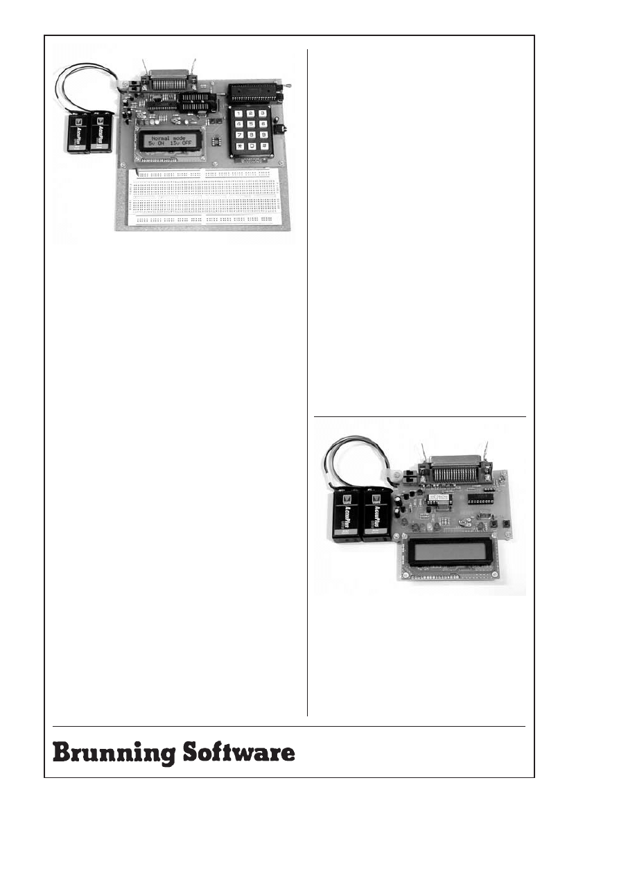
Assembler for the PC
Experimenting with PC Computers with its kit is the easiest way
ever to learn assembly language programming, simple circuit
design and interfacing to a PC. If you have enough intelligence to
understand the English language and you can operate a PC
computer then you have all the necessary background
knowledge. Flashing LEDs, digital to analogue converters, simple
oscilloscope, charging curves, temperature graphs and audio
digitising.
Book Experimenting with PCs. . . . . . . . . . . . . . . . £21.50
Kit 1a 'made up' with software. . . . . . . . . . . . . . . . £45.00
Kit 1u 'unmade' with software. . . . . . . . . . . . . . . . .£38.00
C & C++ for the PC
Experimenting with C & C++ Programmes uses a similar
approach. It teaches us to programme by using C to drive the
simple hardware circuits built using the materials supplied in the
kit. The circuits build up to a storage oscilloscope using relatively
simple C techniques to construct a programme that is by no
means simple. When approached in this way C is only marginally
more difficult than BASIC and infinitely more powerful. C
programmers are always in demand. Ideal for absolute beginners
and experienced programmers.
Book Experimenting with C & C++. . . . . . . . . . . . £24.99
Kit CP2a 'made up' with software. . . . . . . . . . . . . £32.51
Kit CP2u 'unmade' with software. . . . . . . . . . . . . . £26.51
Kit CP2t 'top up' with software. . . . . . . . . . . . . . . . £12.99
The Kits
The assembler and C & C++ kits contain the prototyping board,
lead assemblies, components and programming software to do
all the experiments. The 'made up' kits are supplied ready to start.
The 'unmade' Kits require the prototyping board and leads to be
assembled and soldered. The 'top up' kit CP2t is for readers who
have purchased a kit to go with the first book. The kits do not
include the book.
Hardware required
All systems in this advertisement assume you have a PC (386 or
better) and a printer lead. The experiments require no soldering.
Universal Mid Range PIC Programmer
This is a new advanced design based on our 16F84/C711 programmer. At
the heart of the module is a 28 pin PIC16F872 which is used to handle the
timing, programming and voltage switching requirements. The module has
two ZIF sockets and an 8 pin socket which between them allow most mid
range 8, 18, 28 and 40 pin PICs to be programmed. The plugboard is wired
with a 5 volt supply. The price includes the book
Experimenting with the
PIC16F877 and an integrated suite of programmes to run on a PC.
Beginners should also purchase the book
Experimenting with PIC
Microcontrollers.
The software is an integrated system comprising a text editor, assembler
disassembler, simulator and programming software. The register layouts and
bit names of most mid range PICs are built into the software which allows
the assembler to check that the correct combinations are used. For example
ADIE is used with INTCON for the 16C711 and PIE1 for the 16F877 a tricky
mistake to find which most assemblers miss. The programming is performed
at normal 5 volts and then verified with ±10% applied to ensure that the
device is programmed with a good margin and not poised on the edge of
failure.
Universal Mid Range PIC Programmer
with Experimenting with the PIC16F877
and universal PIC software suite. . . . . . . . . . . . . . . . . . £129.50
Experimenting with PIC Microcontrollers (optional). . . . . . . . £23.99
UK Postage and insurance. . . . . . . . . . . . . . . . . . . . . . . . . . . .£7.50
(Europe postage & Insurance. . . . £9.50. Rest of world . . . . £15.50)
Experimenting with the PIC16F877
This book is supplied with the universal programmer. We start with the
simplest of experiments to get a basic understanding of the PIC16F877
family. Then we look at the 16 bit timer, efficient storage and display of text
messages, simple frequency counter, use a keypad for numbers, letters and
security codes, and examine the 10 bit A/D converter.
Experimenting with PIC Microcontrollers
This book concentrates on the PIC16F84 and PIC16C711, and is the easy
way to get started for anyone who is new to PIC programming. We begin with
four simple experiments, then having gained some practical experience we
study the basic principles of PIC programming, learn about the 8 bit timer,
how to drive the liquid crystal display, create a real time clock, experiment
with the watchdog timer, sleep mode, beeps and music, including a rendition
of Beethoven's
Für Elise. Finally there are two projects to work through,
using the PIC to create a sinewave generator and investigating the power
taken by domestic appliances.
Book: Experimenting with PIC Microcontrollers. . . . . . . . . . . £23.99
16F84/711 Programmer Module with 84/711 software. . . . . £62.51
Ordering Information
Telephone with Visa, Mastercard or Switch, or send cheque/PO for
immediate despatch. All prices include VAT if applicable. Postage must be
added to all orders. UK postage £2.50 per book, £1.00 per kit, maximum
£7.50. Europe postage £3.50 per book, £1.50 per kit. Rest of world £6.50 per
book, £2.50 per kit.
138 The Street, Little Clacton, Clacton-on-sea,
Essex, CO16 9LS. Tel 01255 862308
Getting Started with Microcontrollers
This is supplied as a kit and builds into a high quality general
purpose PIC16F84 programmer. You will need moderate PCB
construction skills.
56 page book with construction details, circuit diagrams, flow
diagrams, PIC data, 4 experimental programmes, and 5
exercises + software suite with text editor, assembler,
disassembler, simulator and programming software +
programmer module in kit form.....£27.50 total plus £2.50
postage.
Liquid crystal display optional extra. . . . . . . . . . £9.00 inc.
ZIF socket (not shown) optional. . . . . . . . . . . . . £8.00 inc.
£129.50
Batteries not included
£27.50
LCD & Batteries not included
Mail order address:
262
Everyday Practical Electronics, April 2001
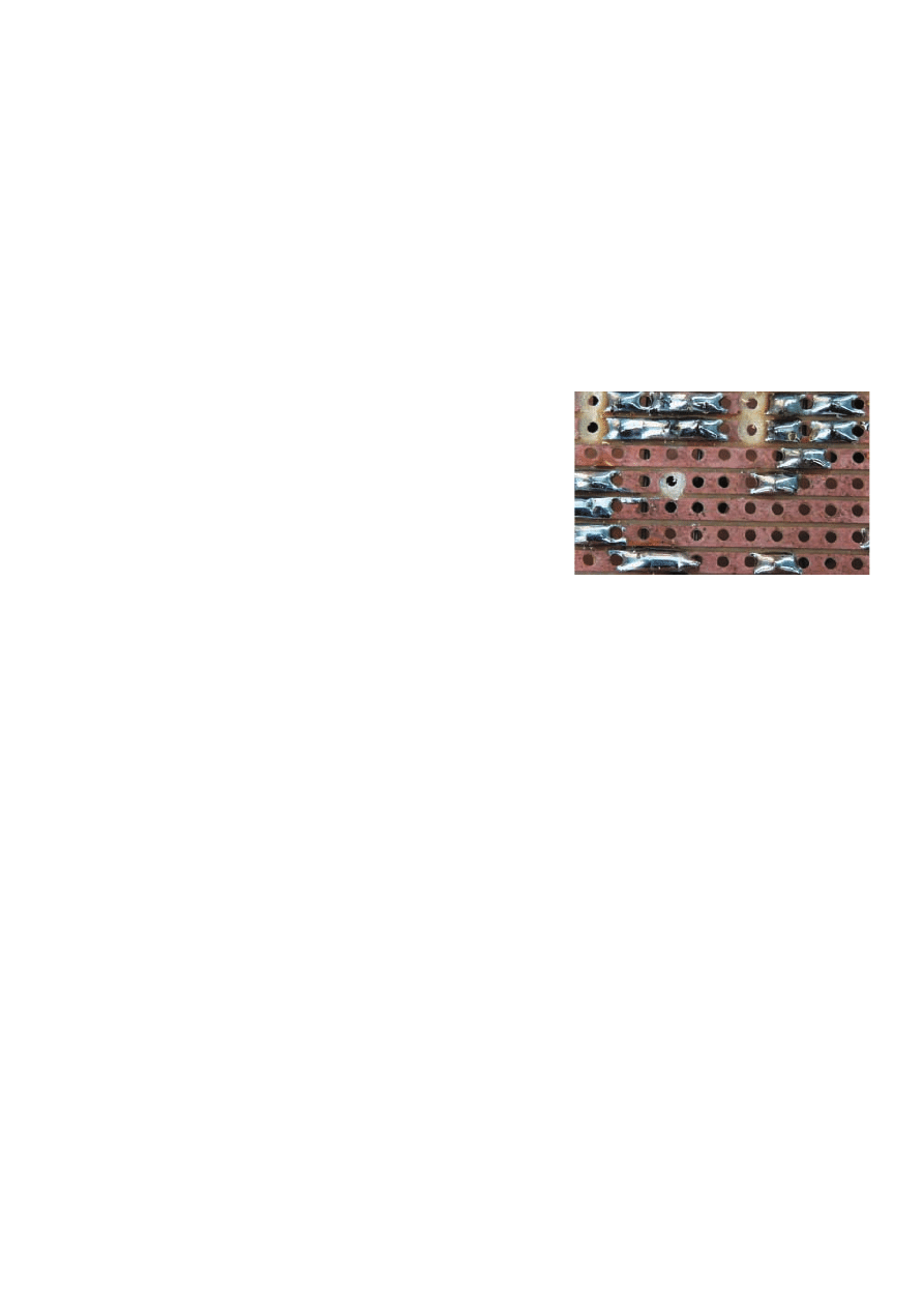
P
ROBABLY
one of the biggest disin-
centives to actually “taking the
plunge” and building your first project is
the fear of failure. It almost certainly
acts as a deterrent to those who have
some experience at electronic project
construction, and wish to build more
ambitious projects than they have
attempted in the past.
In both cases the fears are not total-
ly unfounded in that things can go
wrong and there is no guarantee that a
completed project can be made to
function. On the other hand, the
chances of success are very good
these days.
In the past some methods of con-
struction were not particularly reliable,
and there were a few dodgy compo-
nents on sale. Modern construction
methods are relatively easy to copy,
and faulty components are extremely
rare indeed.
Tarnished Oldies
It is perhaps worth making the point
that most of the recently published
designs are checked far more thor-
oughly than some of those published in
the past. The record of
EPE over the
years is very good in this respect, but if
you “dig up” an old design from another
magazine it might have a fair sprinkling
of errors.
It is unlikely that there will be anyone
willing or able to assist with corrections,
so you are on your own with this type of
thing. Even if you are a fairly experi-
enced constructor and the parts for an
old project can still be obtained, it has
to be regarded as a risky venture.
Wherever possible stick to projects
that have been published in the last
couple of years or so.
Simple Life
Even if you do restrict yourself to
recent designs, things can still go
wrong if you do not proceed with care
and attention. However, most problems
are easily spotted and sorted out.
An important piece of advice for
beginners at practically any creative
hobby is to remember that it is not a
race. There is a temptation to rush the
job in an attempt to get the finished arti-
cle as soon as possible. The aim should
be to make a neat job of things and get
everything right, rather than to finish as
soon as possible.
Another temptation for beginners is
to start off with a grandiose project that
will impress the family and friends. With
modern construction methods a large
project is not necessarily that much
harder to build than a small project, but
it is still advisable to start with some-
thing fairly simple and straightforward.
The smaller the project, the less the
risk of an awkward problem occurring
or a mistake being made. The chances
of success may not always be
massively improved, but they will still
be significantly enhanced.
It is certainly worth repeating the
warning that
beginners should not build
mains powered projects. Battery pow-
ered projects should be safe to build,
and equally safe to fault-find if the fin-
ished unit fails to perform. Mains pow-
ered projects are risky to build unless
you know exactly what you are doing,
and even more risky to check for faults
– the mains can kill!.
Heat of the Moment
Having built a project, if it clearly fails
to work when it is first switched on it is
not a good idea to leave it switched on.
There could be a fault that is causing
high currents to flow somewhere in the
circuit, and this could easily lead to
some expensive damage unless the
power is switched off fairly rapidly.
If there is the characteristic smell of
hot components and the circuit is only
intended to operate at low power levels,
not only should the unit be switched off,
but it should not be switched on again
until the likely cause of the problem has
been located and corrected.
If you have a multimeter it is good
idea to check the current consumption
when initially trying out a new project.
In cases where the current flow is clear-
ly “over the top”, switch off at once. If
the current flow seems reasonable but
the project does not work properly, it
should be safe to leave the unit
switched on so that some further
checks can be made.
Being realistic, a beginner will not have
the necessary technical expertise to
make a full range of meaningful voltage
checks to track down the problem. Even
so, a multimeter is more than a little use-
ful when trying to locate faults. You can
check that the supply is making it to the
on/off switch, and getting past the on/off
switch when the unit is switched on.
Faulty components are rare these
days, but battery clips that do not con-
nect properly are not exactly a rarity,
and some “cheap and cheerful” switch-
es are perhaps a little less consistent
than they should be. With a multimeter
you can also check that the supply is
reaching the appropriate places on the
circuit board, such as the supply pins of
the integrated circuits.
A multimeter usually has a continuity
tester setting that can be used to check
for unwanted short circuits and breaks
in wiring or copper tracks on circuit
boards. The cheapest of analogue or
digital instruments is adequate for this
type of thing.
Clean Sweep
Experience shows that the most like-
ly place for faults to occur is on the
underside of the circuit board. Circuit
boards have become more intricate
over the years, with ever more
connections crammed into smaller
areas. This has greatly increased the
risk of short circuits between copper
tracks due to small blobs or trails of
excess solder.
Really, the circuit board should be
cleaned and thoroughly checked for
short circuits before it is installed in its
case. If this check was not made previ-
ously, then it should certainly be carried
out early in the proceedings when a
new project fails to work. Some dis-
mantling of the project will be required,
but it is essential to get good access to
the underside of the board in order to
check it properly.
Excess flux tends to accumulate on
the underside of circuit boards, making
it difficult to see small pieces of excess
solder. Clean away all the excess flux
using one of the special cleaning fluids
that are available, or simply scrub the
underside of the board using an old
toothbrush. This second method has
the advantage that it will probably
remove any loose pieces of solder that
are causing problems.
With the board properly cleaned, and
even if you have good eyesight, some
solder blobs or trails might be almost
impossible to spot. A loupe or magnify-
ing glass greatly increases the chances
of finding any solder bridges. Search
the board methodically so that any
short circuits that are present will not
be overlooked. If you have a continuity
tester or a multimeter with this facility,
use it to double-check for short circuits.
Any solder bridges that are found
can usually be wiped away with the hot
tip of a soldering iron. Alternatively,
they can be carefully cut away using a
modelling knife.
While inspecting the board keep an
eye out for any other problems. In the
case of a stripboard, have all the
breaks in the strips been cut properly,
or are there one or two thin lines of
track left in place?
In Fig.1, the break just to the left of
centre looks suspicious due to its lack
of symmetry. There is actually a very
thin line of copper still in place just
above the supposed break. That is
quite sufficient to maintain continuity.
PRACTICALLY SPEAKING
Robert Penfold looks at the Techniques of Actually Doing It!
Everyday Practical Electronics, April 2001
263
Fig.1. The break just left of centre looks
a little dubious, and is!

Modern components and solders
make it difficult to produce bad sol-
dered joints, but not impossible. If any
joints have an odd appearance, with an
asymmetric shape or a dull crazed fin-
ish it would be as well to remove the
solder and redo the joint.
Some printed circuit boards have
extremely fine tracks. Are there any
cracks or other breaks in the tracks? A
continuity tester can be useful for
checking for a proper connection
through any “weakest links” in the cop-
per track.
Do some of the joints have an obvi-
ous shortage of solder, or have any
joints been missed out altogether?
Redo any joints where you have been a
bit economic with the solder.
Check and Check Again
When you are sure there are no
problems on the underside of the
board, reassemble the project and
recheck the component layout. Are
components such as electrolytic capac-
itors, diodes, transistors and integrated
circuits fitted the right way round?
Carefully check the markings on the
components against the polarities and
orientations shown in the component
overlay. With most components the cor-
rect orientation is fairly obvious, but we
are all capable of making the odd error
here and there. With transistors, have
any of the leadout wires become
crossed over and fitted in the wrong
holes?
The markings on most integrated cir-
cuits are perfectly clear, but some have
extraneous labels and moulding marks
that can confuse matters. Look careful-
ly to make sure that the notches, dim-
ples, and lines that indicate pin one
really are what you think they are. If in
doubt, examine the chip using a loupe
or magnifying glass. With a careful visu-
al inspection you should be able to see
which marks are “the real thing”.
Getting Physical
If there are any link-wires, make sure
that they join the right pairs of holes.
Check every component to make sure
that each one is in the right place. Try
giving each com-
ponent a firm tug.
This will often
bring to light any
“dry” or missing
joints, with one
lead of the compo-
nent pulling free of
the board. It will
also show up any
components that
have suffered
major physical
damage.
Most compo-
nents are physical-
ly very tough, but
there are some
exceptions. In par-
ticular, you need to
be careful when
dealing with glass
bodied diodes and
open construction
capacitors, such as
some printed circuit
mounting types (see
Fig.2). Try to avoid
bending the leadout
wires close to the
body of glass cased
diodes, since this
can result in the
lead breaking away.
Avoid doing any-
thing that puts a
strain on the glass
body.
With the uncased
capacitors there are
two potential prob-
lems. Any outward
pressure on the
leads tends to tear
them away from the
body of the component. Taking too long
when soldering them into place pro-
duces a similar result with the leads
effectively being desoldered from the
body.
Modern uncased capacitors are
tougher than those from a few years
ago, but care still has to be exercised
when fitting them on a circuit board. If
any forming of the leads is required in
order to fit them in place, proceed care-
fully, holding the leads in place on the
body.
Do any of the components show
signs of overheating? Taking too long to
solder components in place can dam-
age them even though there may be lit-
tle outward sign of any problems. If a
component has been subjected to too
much heat it will usually change colour
slightly. Also, it will usually have a
noticeably shinier or duller appearance.
Are there any components that show
any of these signs when compared to
similar components on the board?. It is
probably worthwhile replacing any
component that looks a little “off
colour”.
Testing – Testing
If you have a multimeter it should be
capable of resistance measurements,
and it may have other ranges that are
suitable for component testing. Most
test meters have a diode checking facil-
ity, and many also have a built-in tran-
sistor tester. If you are lucky there will
also be capacitance ranges.
Where possible, test any dubious
looking components, but bear in mind
that they cannot be tested in-circuit.
With two-lead components at least one
lead must be disconnected from the cir-
cuit board before a measurement is
made, otherwise readings can be
affected by other components in the cir-
cuit (see Fig.3). A few test meters have
a simple in-circuit test facility for tran-
sistors. Where no in-circuit facility is
available it is easier to completely
remove devices from the board for test-
ing, rather than leaving one lead con-
nected to the board.
Careless errors can easily occur in
the hard wiring, so it is well worthwhile
checking this very thoroughly, making
sure that every connection is present
and correct. Where a project works to
some extent, but some of the controls
seem to work erratically or not at all,
the hard wiring is the first place to start
checking.
Many constructors find it helpful to
check each wire against the wiring dia-
gram and then mark it on the diagram.
Where there is a lot of wiring this
makes it easier to spot any missing
connections.
Rotary switches are a common
cause of problems. It is easy to get all
the connections to the outer ring of tags
shifted by one tag, so check this point
very carefully. Do the switches simply
operate the opposite way round to what
you were expecting (on is off, etc.)?
Finally
Errors in electronics publications are
relatively rare these days, but they can
still occur. If a project is giving problems
it is a good idea to check later issues of
the magazine for corrections.
If there seems to be a major discrep-
ancy between the circuit diagram and
the wiring and layout diagrams, the
publisher will often be able to supply a
quick answer if there is a problem. In
most cases though, if your project
accurately matches the published
design it will work. When dealing with a
problem project it helps to keep this in
mind.
264
Everyday Practical Electronics, April 2001
Fig.3. Semi in-circuit testing of a resistor.
Fig.2. Uncased capacitors (left) and glass diodes are not the
toughest of components.
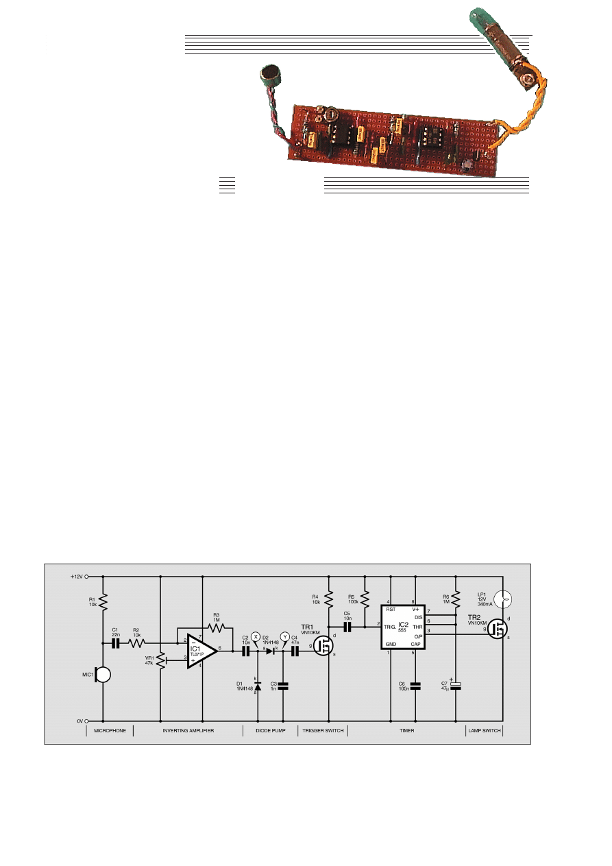
TToopp TTeennnneerrss
A
sound-operated trigger has many
applications. The circuit diagram in
Fig.1. shows how it can be used to
switch on a low voltage lamp. The lamp
might be a porch lamp, or a child’s bedside
night-light, or a lamp on a dark stairway or
corridor.
When the circuit is triggered by a sudden
sound, the lamp comes on and stays on for
about 50 seconds. This allows time for
someone to negotiate the stairs or make
their way along the corridor, or perhaps to
find the switch of the usual lighting and
turn it on. A lamp that comes on whenever
a noise is heard in the vicinity is also an
effective intruder deterrent.
In general, the circuit is most sensitive to
a sharp, crisp sound, such as a handclap. It
is less likely to be triggered by ordinary
conversation or passing traffic.
SWITCHED ON
The output stage of this project is a MOS-
FET transistor, which is capable of switching
up to 500mA. If the project is powered by a
12V supply, a low voltage filament lamp may
be used to provide a reasonable amount of
light. For brighter lighting, it is possible to
substitute a more powerful lamp switched by
a transistor such as a VN66AF, which switch-
es up to 2A.
The circuit can be used for switching
other electrical devices such as:
* An audible warning device such as an
electric bell, a solid-state buzzer or a
siren.
* A relay: use this to switch a more pow-
erful lamp, or a motor.
* A model railway locomotive; the circuit
is triggered by blowing a whistle, caus-
ing the locomotive to start.
The circuit can be run on a 6V supply for
switching a device that operates at 6V.
HOW IT WORKS
The Sound Trigger circuit diagram of
Fig.1 consists of six distinct stages, and
most stages are coupled to the following
stage through a capacitor. The first stage is
the electret microphone, MIC1, which
depends for its action on the changes in
capacitance that occur between a fixed
plate and a plate that is being vibrated by
sound.
There are several kinds of capacitive
microphone, but the electret type has a
permanent charge across the capacitor,
produced by heating the dielectric during
manufacture while maintaining a strong
electrical field between the plates. The
microphone is then cooled and the electric
charge remains.
An electret microphone includes an f.e.t.
amplifier and requires a current to power it.
This is supplied through resistor R1. A
voltage signal is generated across the
microphone when sound is detected and
this signal passes across the capacitor C1 to
the operational amplifier, IC1.
AMPLIFIER
This amplifier, which has f.e.t.. inputs,
is used in inverting mode with its gain set
by the ratio of resistors R2 and R3 to
100.
The trimmer potentiometer VR1 is used
to adjust the voltage at the non-inverting
(+) input to make it equal to the steady
voltage at the inverting (–) input in the
SOUND
TRIGGER
This short collection of projects, some useful, some instructive and some amusing, can be
made for around the ten pounds mark. The estimated cost does not include an enclosure.
All of the projects are built on stripboard, and most have been designed to fit on to boards of
standard dimensions. All of the projects are battery-powered, so are safe to build. In a few
cases in which, by its nature, the project is to be run for long periods, power may be provided
by an inexpensive mains adaptor. Again, the cost of such a unit is not included.
266
Everyday Practical Electronics, April 2001
OWEN BISHOP
Project 8
Fig.1. Complete circuit diagram for the Sound Trigger showing the six distinct stages.

absence of sound. The output of the ampli-
fier then sits midway between the two
power rails.
When sound is received, the output volt-
age of the amplifier (at pin 6) swings above
and below the midway voltage. This alter-
nating signal passes across capacitor C2 to
the next stage.
DIODE PUMP
A single positive swing of the output of
the op.amp is too short to trigger the timer,
and is cancelled when the voltage swings
negative. To avoid this cancelling, we use a
“diode pump’’ to rectify the signal and to
produce a cumulative effect.
The action of this depends on two facts:
* Current can flow through a diode in
only one direction (apart from a rela-
tively small reverse leakage current).
* When the voltage on one plate of a
capacitor is changed suddenly, the
voltage on the other plate immediate-
ly changes by the same amount and in
the same direction.
Consider point X at the junction of
diodes D1 and D2, see Fig.1. As the voltage
from the op.amp (IC1) swings in the posi-
tive direction, the voltage at the junction of
capacitor C2 and diode D2 (point X)
swings positive by the same amount.
Current flows through diode D2 and a
charge builds up on capacitor C3, causing
the voltage at Y to rise. Because of the
charge gradually flowing away through D2,
the voltage at X does not rise as high as that
of the output of IC1.
When the voltage of the output of IC1
swings low, the voltage at X swings in the
negative direction, by the same amount.
Because X was previously at a lower volt-
age than the output, this takes X down to a
negative voltage. Therefore, current now
flows through diode D1 from the 0V line.
The voltage on the plate rises towards 0V.
On the other hand, the charge that has accu-
mulated on capacitor C3 cannot flow back
again through D2.
The overall effect is that the flows of cur-
rent through the diodes raise the voltage at
X as well as the voltage at Y. The two volt-
age rises are in series, so are added togeth-
er. The alternating output from the op.amp
is converted to a sustained signal of
approximately double the peak voltage.
The multiple vibrations of a burst of sound
(for example, a blast on a whistle) result in a
continuous high voltage developing at Y. In
other words, a positive pulse is generated,
which switches on MOSFET TR1 via C4.
TIMER
When transistor TR1 is switched on the
voltage at its drain (d) terminal falls from
+12V to below +4V, which is enough to
trigger timer IC2. This is wired as a mono-
stable multivibrator, which then produces a
single high output pulse from pin 3. This in
turn switches on a second transistor TR2
and current flows through the lamp LP1.
The length of the pulse from IC2
depends on the values of R6 and C6
according to the equation:
t = 1·1RC
With the values given in Fig. 1, the pulse
lasts for just over 50s. For other applications,
you can select different pulse lengths by
choosing appropriate values for R6 or C6.
POWER SUPPLY
The circuit takes around 340mA when
the lamp is lit. It is, therefore, best powered
by a heavy-duty battery, such as two 6V
lantern batteries in series.
It will run for just over 200 hours using
four D-type alkaline cells in a battery hold-
er. Alternatively, use a 500mA 12V d.c.
unregulated mains adapter. For other appli-
cations, it may be operated on a 6V supply
and then requires less current.
CONSTRUCTION
This simple Sound Trigger is built on a
small rectangle of 0·1in matrix stripboard,
size 10 copper strips by 39 holes. (Note
there is no row I.) The component layout,
wiring and details of breaks required in the
copper tracks are shown in Fig.2. The
board layout is fairly straightforward and
assembly should cause no problems. The
use of i.c. sockets is recommended for IC1
and IC2.
It is best to build the Sound Trigger
stage-by-stage, starting with the micro-
phone stage, and testing the output of
each stage as you go. Depending on the
exact type of microphone used, there is a
preferred working voltage, which is
obtained by using a suitable value for
resistor R1.
The microphone used in the prototype
had a preferred voltage of 4·5V, but could
be operated over the range 1·5V to 12V.
There is a reasonable amount of adaptabil-
ity here; with the 10 kilohms dropping
resistor (R1) the voltage across MIC1 was
found to be 7·8V, which is within the
acceptable range.
Checking the operation of the circuit is
easy if you have an oscilloscope, but its
responses can be detected quite well using
a digital multimeter. At this stage, tapping
the microphone results in very small but
irregular variations of voltage at the junc-
tion between R1 and MIC1. If you fail to
detect a signal, do not worry at this stage.
Everyday Practical Electronics, April 2001
267
Resistors
R1, R2, R4 10k (3 off)
R3, R6
1M (2 off)
R5
100k
All 0·25W 5% carbon
film or better
Potentiometer
VR1
47k miniature carbon
preset, horizontal
Capacitors
C1
22n polyester film
C2, C5
10n polyester film (2 off)
C3
1n polyester film
C4
47n polyester film
C6
100n polyester
C7
47µ radial elect. 35V
Semiconductors
D1, D2
1N4148 silicon diode
(2 off)
TR1, TR2
VN10KM, MOSFET
n-channel transistor
(2 off)
IC1
TL071CP, operational
amplifier, bi-f.e.t.
inputs
IC2
555 timer
Miscellaneous
MIC1
electret microphone
insert
LP1
12V 340mA filament
lamp
Stripboard, size 10 strips × 39
holes; 1mm terminal pins (5 off); 8-pin
d.i.l. i.c. socket (2 off); lamp socket
(MBC or to fit LP1); battery holder or
connector for d.c. supply unit; con-
necting wire; solder, etc.
COMPONENTS
Approx. Cost
Guidance Only
£
£8
8
excluding batts.
See
S
SH
HO
OP
P
T
TA
AL
LK
K
p
pa
ag
ge
e
Fig.2. Sound Trigger stripboard component layout, wiring to microphone insert and
lampholder, and details of breaks required in copper tracks.

Adding the inverting amplifier gives a
larger signal.
AMPLIFIER
Next, build the amplifier stage (IC1).
The purpose of preset VR1 is to allow the
voltage at the (+) input of IC1, at pin 3, to
be set to equal the quiescent voltage at the
(–) input (IC1 pin 2). It also has the
function of adjusting the sensitivity of the
circuit.
With the two input voltages exactly
equal, the output voltage at IC1 pin 6 is
close to 6V. This allows sound to make the
output swing freely in either direction and
gives the most sensitive setting.
As the action of the diode pump
depends on the amount of voltage swing,
restricting the swing reduces the pump-
ing action. Setting the output voltage
higher or lower restricts the amount by
which it can swing, so reducing sensitiv-
ity. For the present, adjust preset VR1 to
bring the output of the op.amp as close as
possible to 6V.
When adding the diode pump stage, take
care to get the diodes the right way round.
They usually have a black band around
them at the cathode end (marked k in the
diagrams). Test the “pump’’ by monitoring
the voltage at point Y. It normally rests at a
few tens of millivolts above zero but rises
sharply to 5V or more when the micro-
phone is tapped. A digital meter may not
readily detect this unless it has a ‘‘record’’
function, but the peak is easy to see on an
oscilloscope.
ON TIME
The next stage is the timer. Before insert-
ing IC2 in its socket, check the voltages at the
socket for pin 2. This is normally very close
to 12V, with a sharp drop to around 4V when
the microphone is tapped. This downward
spike is hard to detect with a multimeter.
Insert IC2 in its socket and check that its
output at pin 3 rises from 0V to 12V when
the microphone is tapped. If it does not,
suspect the connections to pin 2 through
C4, TR1 and C5.
The circuit will certainly need some
checking and preset VR1 may need set-
ting, so it is advisable to solder a 100k
9
resistor (or any other close value) in paral-
lel with resistor R6. This shortens the
‘‘on’’ time to 5s, and makes testing much
speedier.
When completed, the circuit responds to
claps, bangs and whistles at distances of a
few metres from the microphone. It also
responds to spoken phrases at distances of
around half a metre.
$
268
Everyday Practical Electronics, April 2001
Close-up of the completed circuit board showing the general layout of components.
A Complete range of regulated inverters to power 220V and 240V AC
equipment via a car, lorry or boat battery. Due to their high performance
(>90%) the inverters generate very little heat. The high stability of the
output frequency (+/-1%) makes them equally suitable to power
sensitive devices.
These inverters generate a modified sine wave, which are considerably superior to the square waves which are produced by
most other inverters. Due to this superior feature they are capable of powering electrical equipment such as TV,s, videos,
desktop & notepad computers, microwave ovens, electrical lamps, pumps, battery chargers, etc.
Low Battery Alarm
The inverters give an audible warning signal when the battery voltage is lower than 10.5V (21V for the 24V version). The inverter
automatically shuts off when the battery voltage drops below 10V (20V for the 24V version). Fuse protected input circuitry.
A COMPLETE RANGE OF
INVERTERS
150W TO 1000W - 12V & 24V
W W W
W W W
. B K E L E C . C O M / I N V E R T E R S . H T M
. B K E L E C . C O M / I N V E R T E R S . H T M
Order Code
651.581
651.578
651.582
651.585
651.583
651.593
651.587
651.597
Power
150W Continuous
150W Continuous
300W Continuous
300W Continuous
600W Continuous
600W Continuous
1000W Continuous
1000W Continuous
Voltage
12V
24V
12V
24V
12V
24V
12V
24V
Price
£38.49
£38.49
£54.36
£54.36
£118.42
£118.42
£174.60
£174.60
All prices are inclusive of V.A.T. Carriage £6.00 Per Order
For Full Specifications View our web site at:-
B.K. ELECTRONICS
UNIT 1, COMET WAY, SOUTHEND-ON-SEA, ESSEX. SS2 6TR
TEL.: +44(0)1702-527572 FAX.:+44(0)1702-420243
Many uses include:-
*
Fetes
*
Fairgrounds
*
Airshows
*
Picnics
*
Camping
*
Caravans
*
Boats
*
Carnivals
*
Field Research and
*
Amateur Radio field days * Powering Desktop & Notepad
Computers.
DELIVERY CHARGES ARE £6-00 PER ORDER. OFFICIAL
ORDERS FROM SCHOOLS, COLLEGES, GOVT. BODIES, PLC,S
ETC. PRICES ARE INCLUSIVE OF V.A.T. SALES COUNTER. VISA
AND ACCESS ACCEPTED BY POST, PHONE OR FAX, OR EMAIL
US AT SALES@BKELEC.COM ALTERNATIVELY SEND CHEQUE
OR POSTAL ORDERS MADE PAYABLE TO BK ELECTRONICS.
ILLUSTRATION SHOWN IS 651.583 600W VERSION
REF D3
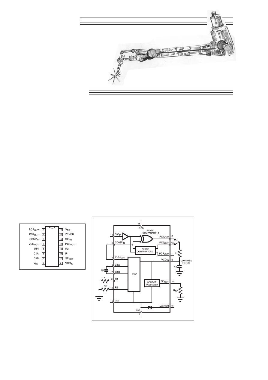
CIRCUIT
SURGERY
web sites,
for example going to
www.philips.com and searching for 4046
or HEF4046B should get you access to
data sheets in Adobe Acrobat PDF format.
You will need Acrobat Reader for this, and
if it is not already on your system it is
available as a free download from
www.adobe.com.
That’s Typical
In a typical PLL design, you will know
either the VCO centre frequency (f
O
, which
it produces when the control voltage is
around half the supply voltage), or you
will know the required lock range (f
min
to
f
max
), which will be centred on the VCO
centre frequency.
If you know f
max
you can select suitable
values for resistor R2 and capacitor C1
using graphs provided on the data sheet.
The ratio R2/R1 is related to the ratio
f
max
/f
min
so now you have R2 (and assum-
ing you know f
min
)
you can select R1
using another graph
given in the data
sheet.
The VCO can also
be operated in “no
offset” mode with R2
open circuit. In this
case you set f
max
as
twice the VCO centre
frequency and select
R1 and C1 from yet
another graph on the
data sheet.
The two phase
comparators operate
on different princi-
ples and have differ-
ent characteristics,
benefits and potential
problems. Phase
comparator 1 is sim-
ply an XOR gate as
depicted by the inter-
nal circuit diagram of
the 4046 (Fig.2.). The
waveforms associated
with it are shown in
Fig. 3a.
filter. If pin 10 is not used it should be left
open-circuit (i.e R
SF
is not required).
Pin 15 is connected to an internal Zener
diode of about +7V. This may seem a bit
strange, but the 4046 is very sensitive to
supply voltage variation and the Zener is
provided in case it is needed to help regu-
late the supply to the chip.
Locking On
To use the PLL you need to decide on the
“lock” range frequencies (which deter-
mines the VCO frequencies and hence C1,
R1 and R2), the low-pass filter values (R3
and C2), and which phase comparator to
use. None of this is trivial but we do not
have the space here to discuss it in great
detail.
If you want to get the best out of the
4046 you need to consult the data sheets
and application notes from the manufactur-
ers. These are usually available from their
L
AST
month we looked at the basic
principles of phase-locked loops
(PLLs) in response to reader Malcolm
Wiles’ request. His colleagues would
spend their lunchtimes in the pub talking
about PLLs but Malcolm never found out
what they were until now!
As he suspected, they are pretty useful
devices, but they can be quite complex –
so there’s plenty to talk about (and a vast
volume of books and academic papers on
the subject if you care to look . . .)
PLLs Continued . . .
This month we will take a look at the
4046, a 16-pin PLL chip from the 4000
CMOS logic series, which is probably one
of the most popular PLL devices amongst
those hobbyists who use them. The pin-out
of the 4046 is shown in Fig. 1, whilst Fig.
2 shows an internal block diagram and the
connection of the key external components
required in even the most basic 4046-based
PLL.
You will recall from last month’s column
that the main parts of a PLL are the phase
comparator, the VCO and the low-pass fil-
ter. The 4046 contains the first two of these
(in fact there are two phase comparators to
choose from); however, the low-pass filter
is made using external components (resis-
tor R3 and capacitor C2 in Fig. 2).
Pin 10 (SF
OUT
) provides a source follow-
er from the low-pass filter output (VCO
input), so that this signal appears as the
voltage across R
SF
and can be used else-
where in your circuit without loading the
Regular Clinic
ALAN WINSTANLEY
and IAN BELL
Everyday Practical Electronics, April 2001
269
Bravely our surgeons explore the depths of phase-locked loops, or skim the surface anyway.
Fig.1. Pinout details for the 4046
CMOS phase-locked loop i.c.
Fig.2. Block schematic of the internal structure of the 4046
phase-locked chip, together with external low-pass filter
components (R3 and C2).
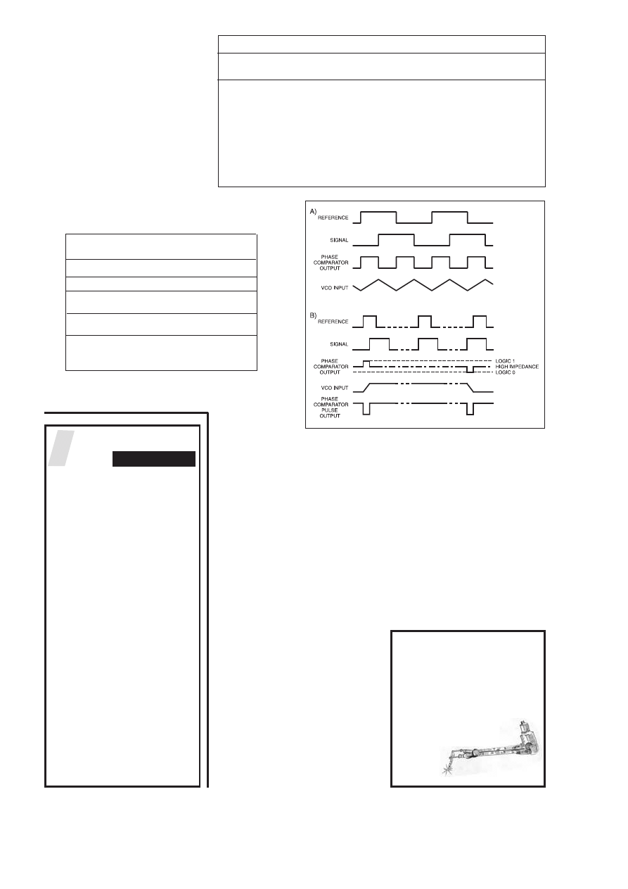
In effect phase comparator 2 produces
two bursts of pulses to charge or dis-
charge the filter capacitor as required, but
is otherwise disconnected from the filter.
Phase comparator 2 also has another
output called PCP
OUT
(phase comparator
pulse output) on pin 1 which can be used
to tell when the PLL is locked. Table 1
shows the outputs produced by phase
comparator 2 under various conditions.
Typical waveforms for phase comparator
2 are shown in Fig.3b. Some of the prop-
erties of the phase comparators are com-
pared in Table 2.
Table 1 and Table 2 only scratch the
surface when investigating phase-locked
loop applications – 500-page text books
are available showing much more of the
same!
On Time
The loop filter should use the longest
RC time possible for the application. This
depends on the speed with which the
input frequency changes.
If the RC time constant of the loop fil-
ter is too long the PLL will not move fast
enough to track changes. If it is too short,
the VCO frequency will jump around too
much, in the worst case responding to
individual cycles of the input signal.
The performance of the PLL can be
improved by using a resistor in series
with C2 (e.g. from the “negative” side of
C2 in series to ground, but not shown on
Fig. 2). This produces damping in the loop
filter and makes the PLL more stable. A
typical value for this resistor is about a
tenth of the value of R3.
As you can see Malcolm, phase-locked
loops can be as complex as you want to
make them. We can’t hope to cover them
in any further depth in this column, and
there’s probably no substitute for testing
typical device chips on a workbench
armed with a signal generator and a good
oscilloscope. At least you now have an
introduction to them, and you’ll be able to
bluff your way through dinner time ses-
sions with your hardware colleagues at the
pub! I.M.B.
270
Everyday Practical Electronics, April 2001
CIRCUIT THERAPY
Circuit Surgery is your column. If you
have any queries or comments, please
write to: Alan Winstanley,
Circuit Surgery,
Wimborne Publishing Ltd., Allen House,
East Borough, Wimborne, Dorset, BH21
1PF, United Kingdom. E-mail (no attach-
ments)
alan@epemag.demon.co.uk.
Please indicate if your query is not for pub-
lication. A personal reply can-
not be guaranteed but we will
try to publish representative
answers in this column.
Table 2: Phase Comparators Compared
Property
Phase Comparator 1
Phase Comparator 2
(pin 2)
(pin 13)
Lock range
Full VCO range f
min
to f
max
Full VCO range f
min
to f
max
Capture range
Depends on low-pass filter
Equal to lock range
Signal noise rejection
Good
Poor
Will it lock on
Yes
No
harmonics of f
o
?
Effect of input
Best performance at 50%
Does not matter
duty cycle
Output when fully
f
o
(the VCO centre frequency)
f
min
out of lock
The VCO output is connected directly to
the phase comparator reference input
(COMP
IN
) on pin 3. The input signal itself
should be capacitively coupled to the sig-
nal input (SIG
IN
) on pin 14. When using
phase comparator 1, the signal and refer-
ence inputs must both have 50 per cent
duty cycle in order to achieve the maxi-
mum lock range.
Phase Two
Phase comparator 2 is more complicated
than phase comparator 1. It is a state
machine which changes state when logic
transitions occur on either the signal or ref-
erence inputs. Depending on the current
state of phase comparator 2, it outputs a
logic 1, a logic 0 or a high impedance state.
Table 1: Phase Comparator 2 output truth table
Signal frequency ( f) PC2
OUT
PCP
OUT
and phase (
.
.)
f
signal
> f
reference
Mainly 1
Mainly 0
f
signal
< f
reference
Mainly 0
Mainly 0
f
signal
= f
reference
Mainly 1
Mainly 0
.
signal
lags
.
reference
f
signal
= f
reference
Mainly 0
Mainly 0
.
signal
leads
.
reference
f
signal
= f
reference
High impedance
1
.
signal
=
.
reference
PLL is locked
Fig.3. (a) Phase comparator 1 typical waveforms and (b)
some typical waveforms for phase comparator 2.
R
evival
COMPANY
THE
seeks an
EXPERIENCED
AV TECHNICIAN
in the Surrey area for a few
hours work per week
Hours and rates negotiable
Please send CV to:
A. Dale
The Revival Co
Unit 6
4 Manorgate Road
Kingston
KT2 7EL
Tel: 020 8549 6465
Fax: 020 8541 5873
a.dale@revivalco.co.uk
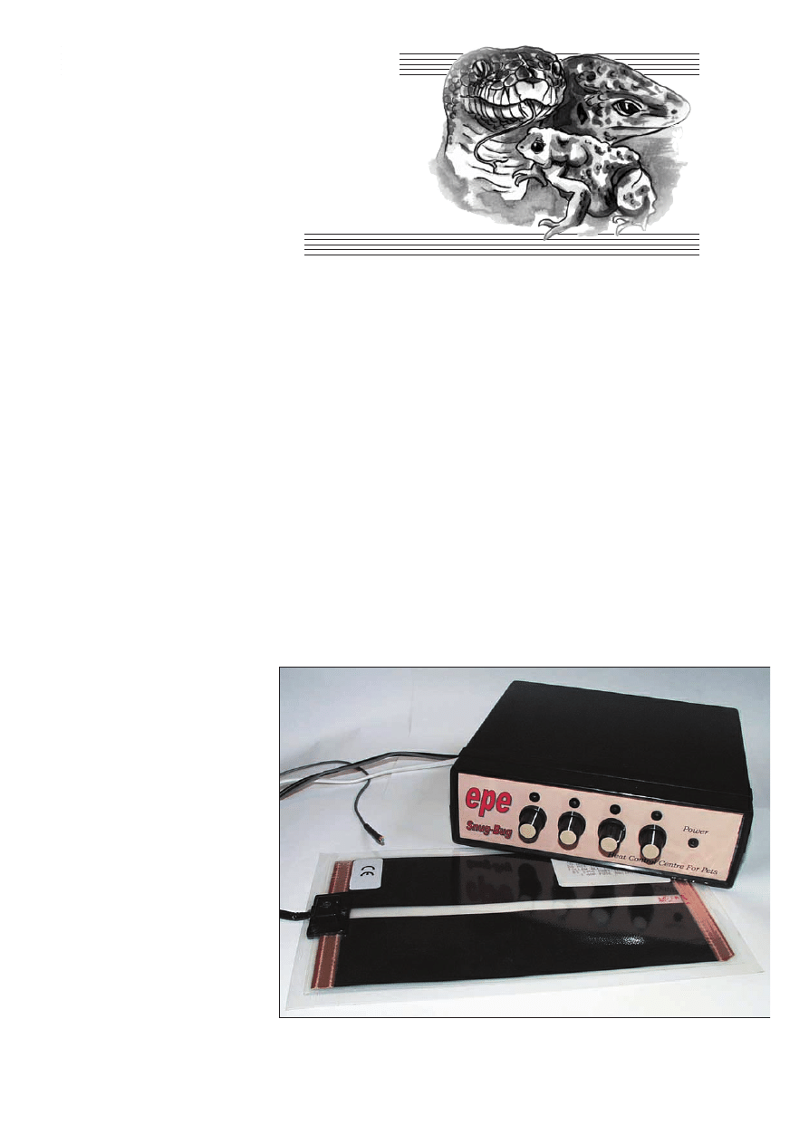
CCoonnssttrruuccttiioonnaall PPrroojjeecctt
K
EEPING
tropical pets is a rewarding
and popular hobby. In order that the
pets thrive the temperature of the
environment must be maintained to within
a few degrees and pet stores supply heating
pads and thermostatic controllers for this
purpose. If more than one habitat is
involved then a separate controller/pad
system should be used for each, especially
if the habitats are located any distance
apart or are in different rooms of the house.
This article describes a 4-channel ther-
mostatic controller intended for use with
up to four (dry) heat pads. The temperature
range is designed to be from about 25°C to
40°C, though each pad may be individual-
ly calibrated to the user’s requirements.
Fish tanks and other wet environments
where the heating device needs to be
immersed in water are NOT dealt with in
this article, since there may be certain safe-
ty issues unknown to the author – the
author’s children have snakes and toads
only.
DESIGN
CONSIDERATIONS
The most important features considered
when designing the circuit were:
) Safety – the sensors must be well
isolated from harmful voltages.
) Cheap sensors requiring minimal
wiring.
) Good noise-immunity on the sensors,
allowing long wired connections.
) Easy to interface to the mains supply
and no mains interference.
) Good temperature control stability.
) Easy to calibrate and change
temperature ranges.
) The circuit should be as simple as
possible, requiring only a basic grasp of
project construction.
CHOICE OF
COMPONENTS
A good deal of thought was given to the
type of sensors to use. Three possibilities
presented themselves: thermistors, thermo-
couples and semiconductor sensors.
Thermocouples would be a good choice
but require special interfacing – a ‘‘cold
junction compensation’’ circuit – and
expensive cable and connectors to work
correctly. Active sensors, like the LM35
from National Semiconductors, need
three-core cable, and in the author’s expe-
rience, can require a lot of attention with
regard to decoupling if long cables are
used.
This left only one possibility – ther-
mistors. These are easy to use, have good
linearity, fast response time and are sim-
ple to incorporate in a bridge circuit
(more of this later). No special connec-
tors or cables are needed. They are sim-
ply resistive devices.
The thermistors chosen are 10 kilohm
NTC types. The value of 10k is the manu-
facturer’s quoted typical resistance of the
device at either 20°C or 25°C. This value
decreases with an increase in temperature
(hence NTC – negative temperature
coefficient).
Having this relatively low resistance
greatly reduces the risk of noise pick-up on
the connecting cables. The prototype has
been successfully tested with 25 metres of
light-weight mains cable in a typical home
environment.
MAINS SWITCHING
Most domestic appliances such as
refrigerators and deep-freezers switch the
mains current by way of mechanical
relays. These will be heard clicking on and
off periodically, and on older appliances
will also be heard on any a.m. radio within
a hundred yards radius! This noise is
caused because the relay switches irre-
spective of the mains supply waveform.
Fortunately to reduce mains-borne noise
there is a simple, if more expensive, solu-
tion open to us called “solid-state relays’’.
These fully encapsulated devices comprise
an optical isolating/coupling device driven
by low voltage d.c. and a mains phase sen-
sor which both combine to control an inter-
nal triac. A triac is a bi-directional switch
which has the ability to switch mains volt-
age of either phase, giving “full-wave
control’’.
The point on the mains waveform at
which switching will take place is gov-
erned by an internal phase sensor, and is
EPE
SNUG-BUG
A 4-channel personal central
heating system, with sensors,
for your tropical pets home.
MIKE DELANEY
Everyday Practical Electronics, April 2001
271
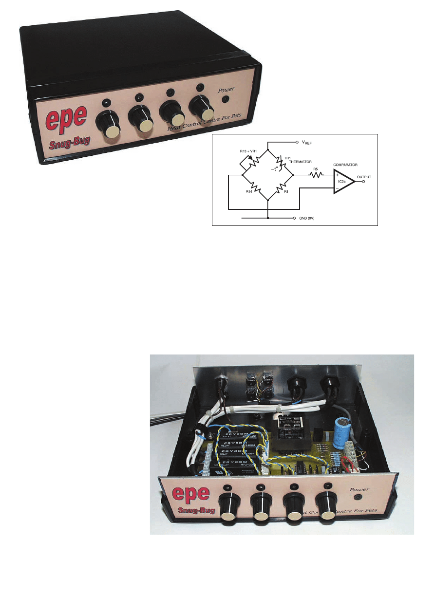
allowed to happen only when the phase is
very close to zero volts. Thus, it is only a
matter of turning on what is effectively an
l.e.d. to obtain silent switching of the sup-
ply to the heater pads.
A GOOD REFERENCE
In order to make sure the temperature
remains constant over time a good voltage
reference i.c. is used. The actual device
chosen needed to satisfy two major crite-
ria: it must be stable, and it must be able to
drive a couple of milliamps at least with-
out ‘‘running out of steam’’.
This is necessary because the thermis-
tors are low resistance types, and there are
up to four connected at any one time. Of
course, it would be possible to use a nor-
mal Zener diode circuit with an op.amp
buffer, but this was not aesthetically pleas-
ing, it would take up more p.c.b. area and
could add to circuit drift.
Looking through some components cat-
alogues produced the ideal device from
Analog Devices, the REF-03CNB which is
a 2·5V reference with a load current rating
of 20mA. Available in a standard 8-pin
package, the published stability data is
also more than satisfactory for the project.
HOT UNDER THE
COLLAR
Calibration of any type, be it frequency,
wind speed, altitude etc. brings with it a
chicken-or-egg situation. Before it is possi-
ble to set up your measuring device it is nec-
essary to know the value of the input, but
how do you know its value in the first place?
Fortunately, as far as this project is
concerned there are reasonably accurate
thermometers available at pet stores for
checking the temperature within the
ranges which interest us. Absolute accura-
cy is not critical, it is not as if we are keep-
ing a volatile liquid within very tight
limits, so it is sufficient to use a standard
thermometer as our reference sensor.
BRIDGE WORK
Temperature measurement is carried out
using a resistive bridge circuit, where one
leg of the bridge is connected to the ther-
mistor and the other to the reference volt-
age. By comparing the voltage across the
thermistor it is possible to determine
whether its resistance, and hence the
The output of the bridge is applied to
IC2a, one quarter of an LM339 comparator,
the output from the thermistor connecting to
the non-inverting input (pin 5), and VR1
wiper connecting to the inverting input (pin
4). Varying the wiper position of VR1 will,
therefore, vary the voltage applied to the
inverting input, pin 4, and as the thermistor
resistance varies with temperature, the volt-
age on pin 5 of the IC2a will also vary.
When the voltage on the non-inverting input
is greater than that on the inverting the out-
put on pin 2 will go high.
Consider what happens as the temperature
applied to thermistor TH1 increases. Since
the NTC thermistor’s resistance decreases as
the temperature increases the voltage
applied to the non-inverting input will
increase and the output of IC2a will go high
when the voltage from the thermocouple is
greater than the voltage from the control
potentiometer VR1.
Looking at the full circuit diagram,
Fig.2, it can be seen that in order for the
opto-coupler (l.e.d.) within IC3 to turn on
the output from IC2a must be low so that it
sinks current. Thus, increasing tempera-
ture will turn IC3 off, and decreasing tem-
perature will turn it on. In order to turn IC3
off when there is no thermistor plugged in
the full reference voltage (V
REF
) is con-
nected to the non-inverting input automat-
ically through socket, SK1.
272
Everyday Practical Electronics, April 2001
temperature, is above
or below the preset
value from the refer-
ence. It is then a
simple matter of
switching the heater
on or off as needed.
CIRCUIT
DETAILS
The full circuit dia-
gram for the EPE
Snug-Bug is shown in
Fig.2. As each “channel’’ is identical, only
the action of one will be described here.
A reference voltage of 2·5 Volts is pro-
duced by IC1, a REF-03 8-pin d.i.p. device
from Analog Devices. This reference is
used to drive the bridge components in
each of the four sensor circuits.
The bridge configuration may not be
immediately apparent to the less experi-
enced constructor and one sensor circuit is
reproduced, in simplified form, in Fig.1.
As this shows, the reference voltage is
applied to one end of thermistor TH1, and
also to one end of the R13, VR1, R14
divider chain. The bridge is then ‘‘closed’’
on both of these legs to ground (0V) via
one end of R1 and one end of R14.
Fig.1. Simplified bridge circuit for one thermistor sensor.
The compact and neat wiring inside the completed unit.
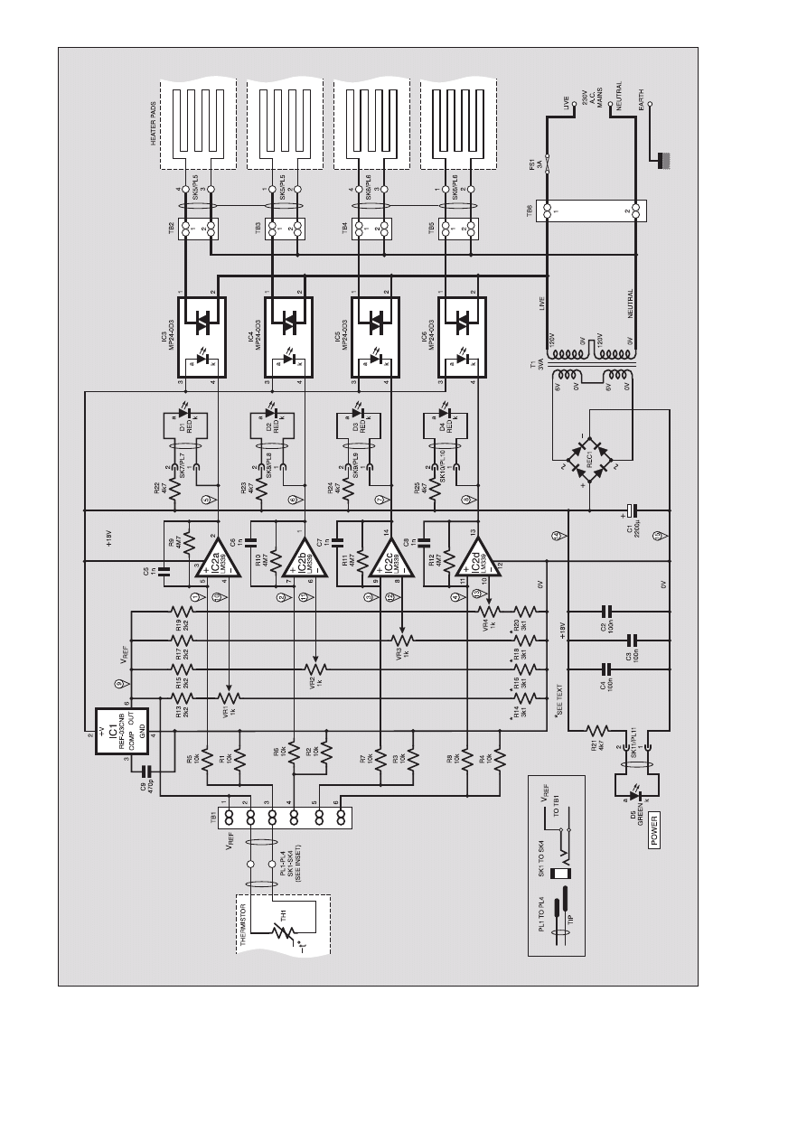
Everyday Practical Electronics, April 2001
273
Fig.2. Complete circuit diagram for the EPE Snug-Bug heat control centre for pets.

Resistor R9 provides positive feedback
(hysteresis) around comparator IC2a,
ensuring that switching is clean with
capacitor C5 preventing any tendency
for high frequency oscillation of the
comparator.
Four l.e.d.s (D1 to D4), with current
limiting resistors (R22 to R25) are includ-
ed in parallel with the opto-triacs IC3 to
IC6 to confirm operation of each channel.
The l.e.d.s in the working design are high
output types to reduce current consump-
tion. If different types are used the four
resistors may be changed to suit.
POWER LINKS
The power supply is a very simple
affair, comprising a transformer, full-wave
rectifier and smoothing components. A
power “on’’ indicator l.e.d. with its associ-
ated resistor are also included.
Several wire links have been included in
the layout, both to assist in the layout and
also to provide useful test points (TP1 to
TP15).
CONSTRUCTION
The EPE Snug-Bug is built on a Euro-
card size printed circuit board (p.c.b.) and
the component layout and full-size under-
side copper foil master is shown in Fig.3.
This board is available from the EPE PCB
Service, code 296.
Assembling the p.c.b. should present no
problems. Start by fitting the resistors and
wire links and fit the mains transformer
last. Use good quality i.c. sockets for IC1
and IC2, turned pin types are preferred. Do
not fit the i.c.s until preliminary testing is
completed.
Capacitors C5 to C8 may need to have
their wires bent slightly in order for them
to fit on the p.c.b. This should be done
using fine nosed pliers, taking care not to
damage the components.
In order to set the maximum and mini-
mum voltages on the control potentiome-
ters’ wipers, the prototype used a value of
3·1 kilohms (3k1) for resistors R14, R16,
R18 and R20 which is not a preferred value.
This value is obtained by using two resis-
tors in series for each, one 1k5 and one 1k6,
numbering the second resistor R14a etc. on
the board component layout in Fig.3.
INTERWIRING
AND BOXING-UP
Interwiring between the front and back
panel mounted components and the circuit
board is shown in Fig.5. The general posi-
tioning of components inside the specified
case can be seen in the photographs.
In the prototype unit, the four tempera-
ture control potentiometers (VR1 to VR4)
are p.c.b.-mounting types and are soldered
directly to the p.c.b. and mounted through
the fascia with spacers placed between the
fascia panel and each control. This makes
for a neat and quick assembly, but requires
more care when drilling the panel. To
assist in this there is a detailed drilling dia-
gram (Fig.4) included, but p.c.b. solder
pins and connecting wires may be used if
desired.
The front panel l.e.d.s (D1 to D4) are
mounted through plastic insulating collars
of the type used to isolate TO-3 style
screws, and are fixed in place using a glue
gun. Each l.e.d. is connected to the p.c.b.
using a Molex connector and wire (see
Component layout on the prototype p.c.b. and wiring to the front panel l.e.d.s. You can
just see the series resistors in front of the potentiometers.
COMPONENTS
Approx. Cost
Guidance Only
£
£7
77
7
excluding heat-pad & case.
Resistors
TH1 to TH4
min. bead
thermistor:
resistance
@ 25°C
10k
9±1%
(4 off – see text)
R1 to R8
10k (8 off)
R9 to R12
4M7 (4 off)
R13, R15,
R17, R19
2k2 (4 off)
R14, R16,
R18, R20
1k6 (4 off)
R14a, R16a,
3k1
R18a, R20a 1k5 (4 off)
}
see text
All 0·6W 1% metal film, except where stated
Potentiometers
VR1 to VR4 1k min. rotary carbon, lin.
(4 off)
Capacitors
C1
2,200 radial elect. 25V, pin
pitch 7·5mm
C2 to C4
100n polyester (3 off)
C5 to C8
1n mylar film (4 off)
C9
470p resin-dipped ceramic
Semiconductors
D1 to D4
3mm red l.e.d. (4 off)
D5
3mm green l.e.d.
IC1
REF03GP 2·5V precision
voltage reference
IC2
LM339 quad voltage
comparator
IC3 to IC6
MP240D3 opto-triac,
with zero switching:
input 3·5V to 32V d.c.;
output switching
3A @ 240V a.c. (4 off)
REC1
100V 2·5A bridge rectifier
(1KAB10E)
Miscellaneous
SK1 to SK4 3·5mm mono switched jack
socket, plastic body,
panel mounting (4 off)
PL1 to PL4
3·5mm mono jack plug
(4 off)
SK5, SK6
4-pin 2A 250V mains
socket, chassis mounting
(Bulgin SA2368 – 2 off)
PL5, PL6
4-pin 2A 250V mains
line-plug, with shielded
pins (Bulgin SA2367 –
2 off)
SK7 to SK10 2-way 2·54mm (0·1in.)
pitch pin header (4 off)
PL7 to PL10 2-way pin connector (4 off)
and crimp terminal (8 off)
SK11/PL11
3-way pin header,
connector, crimp terminal
(remove centre pin – see
text)
TB1
6-way 16A terminal block,
p.c.b. mounting
TB2 to TB6
2-way 16A terminal block,
p.c.b. mounting (5 off)
T1
3VA mains transformer,
p.c.b. mounting, with
0V-6V, 0V-6V
secondaries
FS1
3A 20mm fuse, with
panel mounting
fuseholder
Printed circuit board available from the
EPE PCB Service, code 296; plastic
(ABS) case, with aluminium front and
back panels, size approx. 203mm (w) x
178mm (d) x 63mm (h); 220V/240V 7W
heater pad, size approx. 150mm x 280mm
(6in. x 11in.) (4 off); 8-pin d.i.l. socket; 14-
pin d.i.l. socket; plastic 15mm diameter,
collet fixing, knob (4 off); strain-relief
grommet; p-clips (2 off); plastic spacer (4
off); 3mm csk bolts, nuts and washers (4
off each); mains cable (see text); multi-
strand connecting wire; heatshrink and
rubber sleeving; solder, etc.
See
S
SH
HO
OP
P
T
TA
AL
LK
K
p
pa
ag
ge
e
274
Everyday Practical Electronics, April 2001
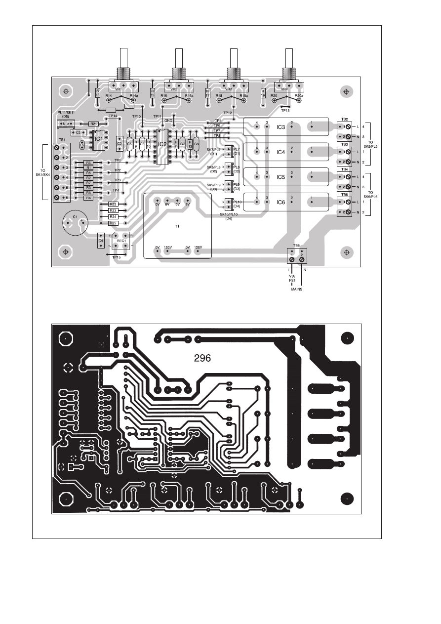
Everyday Practical Electronics, April 2001
275
Fig.3. Printed circuit board component layout and
full-size copper foil master for the EPE Snug-Bug.
Note that resistors R14, R16, R18 and R20 are
made up of two resistors wired in parallel. See text
and components list.
6·25in. (156mm)
3·88in.
(97mm)
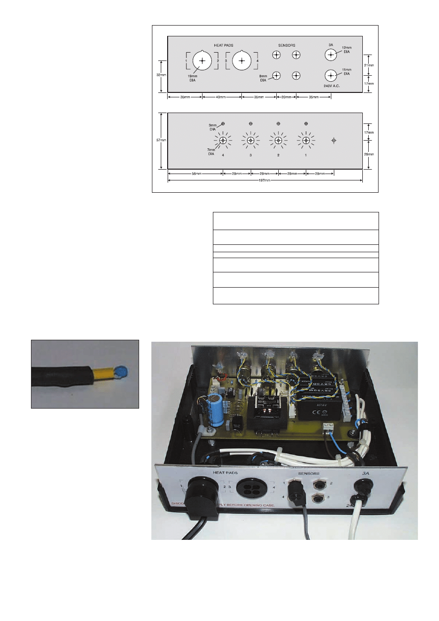
276
Everyday Practical Electronics, April 2001
Test Point
TP No.
TP Name
Voltage
Comments
1–4
Non-Inverting
*
Varies with temperature
(IC2) Inputs
5–8
Output
1·2V to V
CC
Almost rail-to-rail
9
V.Ref.
2·50V
Stable reference voltage.
10–13
Wiper
1·23V to 1·62V Varies depending upon
(VR1 to VR4)
pot. wiper position.
14
Supply Voltage
18V d.c.
(V
CC
)
15
Supply
0V
Zero
Notes on the test point voltages:
*
TP1 to TP4 – this should be
approximately 1·25V d.c. but will depend upon the temperature of
the thermistor. TP15 – all voltages shown are measured with
respect to this point 0V (Gnd).
Table 1: Test Point Voltages
photographs), photographs though again
these may be soldered directly to solder
pins instead and the l.e.d.s mounted in con-
ventional plastic holders.
The power on indicator l.e.d. is connected
using a three-pin Molex plug and socket
with the centre pin removed. This was done
to facilitate removal of the circuit board dur-
ing initial testing whilst maintaining a rea-
sonable thickness of ground copper.
The board terminal blocks TB2 to TB5
are 2-way p.c.b. mounting types rated at
16A, with 5mm pin spacing. The connec-
tors SK5 and SK6 for the switched sup-
plies (from TB2 to TB5) to the heater pads
are panel mounting four-way mains types
rated at 2A. Only correctly rated and safe-
ty protected connectors for SK5/PL5 and
SK6/PL6 should be used!
Standard 3·5mm mono jack plugs and
sockets are used to connect the thermistors,
the sockets should be the type with break
contacts. One word of caution: the author
has found that it is possible to buy “stan-
dard’’ plugs which do not make a good
connection to the wipers in “standard’’
sockets. This causes the thermistor to
appear intermittent or completely open circuit
(see fault-finding later). Buying both plug and socket from the
same supplier and careful testing is recommended.
A fuse rated at 5A should be used in the mains input line,
along with a cable relief grommet and P-clips and cable ties for
all of the cables.
THERMISTOR PROBES
Two types of thermistor are available (see Shoptalk page),
one has p.t.f.e. insulated leads ready fitted and the other has
bare wires. Whichever type you choose it is desirable to insulate
all connections using heat-shrink sleeving and silicone rubber
after soldering. Waterproofing will help to prevent corrosion of
the wires and eventual sensor failure.
The type of wire used to connect the thermistors to the control
unit is not critical. The author has successfully used single-core
screened (‘‘microphone’’ cable) and also unscreened lightweight
mains cable. If a long run is required it is probably better to use
mains cable since it is easy to fix to skirting boards etc and is
stronger than lightweight types.
TEST AND
CALIBRATION
Be aware that mains voltages are pre-
sent at various points on the circuit board
and case back panel. Use insulating tape
to cover exposed joints on the underside
of the board.
To carry out tests and calibration you
will require the following equipment:
Digital multimeter; mono 3·5mm plug,
on which the centre (tip) and outer solder
connections have been connected together;
small lump of Blu-Tack or similar; two
2cm thick (approximately) pieces of poly-
styrene slightly larger than the heater
pad/s; heater pad/s wired to the output
plug/s; thermistor/s wired to 3·5mm jack
plug/s.
Fig.4. Drilling and dimension guide for the aluminium front and rear panels.
The rear panel sockets, fuse and mains cable positioning.
Make sure the thermistor leads are fully
insulated.
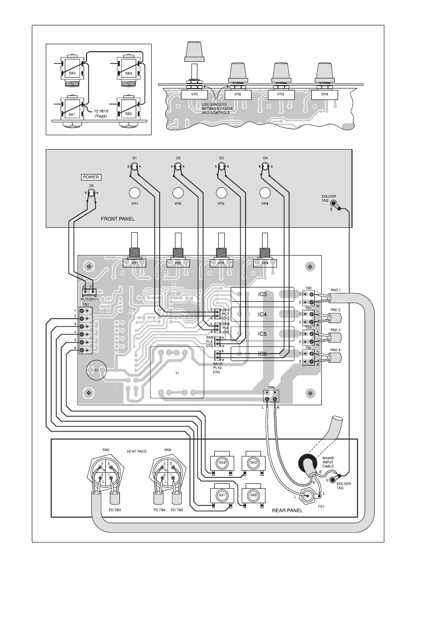
Everyday Practical Electronics, April 2001
277
Fig.5. Interwiring from the circuit board to front and rear panel mounted components. The inset diagram (top left) shows the
interwiring between to the switched jack socket tags.

278
Everyday Practical Electronics, April 2001
Before applying power carefully check
that all the components are placed correct-
ly and there are no solder bridges or dry
joints.
As mentioned earlier, several wire link
test points have been included on the cir-
cuit board to assist fault finding. These are
shown as numbered ‘‘Ice Cream Cornets’’
(the author’s children’s description!) on the
circuit diagram, Fig.2. Table 1 shows typi-
cal voltages and these should be measured
using a digital voltmeter.
Initial testing should be carried out with-
out the thermistors connected to confirm
that the outputs from the comparators are
high and l.e.d.s D1 to D4 are off. Check
that each of the outputs from the control
pots at test points TP10 to TP13 changes as
they are turned and that the l.e.d.s remain
off.
Now plug the temporary 3·5mm “short-
ing plug’’ into each thermistor socket (SK1
to SK4) in turn and check that the com-
parator outputs go low and the l.e.d.s turn
on. Once again, adjusting pots VR1 to VR4
should not have any effect, the shorted out
channel must remain on.
THERMISTOR CHECK
Having completed these checks plug in
the thermistor probes. It should be noted
that there are two REF connections on ter-
minal block TB1, both pin 1 and pin 2, and
it does not matter which is used for which
probe. This was done in order to make it
easier to connect multiple wires to the one
connector.
Embed all of the thermistors and the
“standard’’ glass thermometer bulb in the
Blu-Tack and allow time for the tempera-
ture to stabilise. When this has settled
adjust each of the four controls and con-
firm that each channel l.e.d. turns on and
off, and do so at the same position provid-
ed the temperature is between the lower
and upper thresholds. If the ambient tem-
perature is outside of these limits re-posi-
tion the thermistors etc. to suit.
Check the voltage outputs from the ther-
mistors, test points TP1 to TP4 inclusive.
The ‘‘typical’’ voltage here (Table 1)
applies ONLY to the author’s unit mea-
sured at 20°C – thermistors vary slightly.
Nevertheless, the voltages should be with-
in a few millivolts of those shown when the
temperature is 20°C.
HEAT CHECK
If all appears to be correct turn off the
supply and connect one heater pad, say in
Channel One position. Using the Blu-Tack
stick the thermistor and thermometer to the
pad. Insulate the heating pad using two
pieces of polystyrene so that it makes a
“sandwich’’ and place a book on top to
ensure good thermal contact.
Apply the mains and turn the relevant pot.
fully counter-clockwise so that the channel
l.e.d. turns off. Now advance the control so
that the associated opto-triac switches and
power to the heater pad is turned on. Check
that the temperature of the pad increases and
that the controller switches the power off
when the upper temperature limit is reached.
Note this temperature from the thermometer.
The temperature of the heater pad will start
to fall until the power is once again automati-
cally applied to the heater. When
this happens note this
t e m p e r a t u r e
also.
U s i n g
the digi-
tal multi-
meter now
check the volt-
age present at the test point TP10 (for Channel
One) and make a note of this.
It is now possible to check the operation of
the other three channels by plugging the ther-
mistor and heater pad into each of the other
channels in turn and setting the control pots
so that the same voltage is present on all the
wipers (TP11 to TP13). This should result in
the pad temperature remaining the same to
within a degree or so.
FINAL SETTING
Next check the other three heater pads and
thermistors by making polystyrene sand-
wiches and monitoring the temperature of
each with the pot wiper voltages set identi-
cally to Channel One. This will confirm the
accuracy of each thermistor and bridge
components.
When you are satisfied that the circuit
is functioning correctly set each channel
to whatever temperature span is desired
by changing the values of series combi-
nation resistors R14/a, R16/a, R18/a and
R20/a and repeating the calibration
process.
INSTALLATION
It is now simply a case of installing the
thermistors in the animals’ environments,
monitoring the temperature switching
points and noting the position of the con-
trol knobs when the desired temperature is
achieved.
When installing the thermistors it is
important that the temperature inside the
environment is monitored, i.e. where the ani-
mal is and not on the
outside. This is
most easily
a c h i e v e d
by using a small
amount of silicone rub-
ber to act as a heat transfer
medium and waterproof tape to hold
it in place on the floor of the tank/housing.
The heater pad, of course, remains on the
outside of the tank as usual. It is important
that no matter how the sensor is attached to
the tank the animal cannot lift it off the sur-
face being sensed.
FAULT FINDING
If the circuit does not work, referring to the
list of voltages in Table 1 should allow analy-
sis to component level. Incorrectly placed
components, solder bridges and bent i.c. pins
are the first things to check for.
As mentioned earlier, the only problem
encountered during the building of the
Snug-Bug was caused by incompatibility
between the thermistor jack plugs and
sockets. This problem is easy to check for
– measure the voltage present at the non-
inverting inputs of the comparator (IC1)
when the thermistors are plugged in. If any
of them gives a zero reading then the ther-
mistor is open-circuit.
$
ORDER YOUR COPY NOW
Everyday Practical Electronics is published on the second Thursday of each month and distributed S.O.R. by COMAG
Make sure of your copy of
EPE each month – cut out or photostat this form, fill it in and hand it to your newsagent.
NEWSAGENTS ORDER FORM
Please reserve/deliver a copy of
Everyday
Practical Electronics
for me each month
Signed . . . . . . . . . . . . . . . . . . . . . . . . . . . . . . . . . . .
Name and Address . . . . . . . . . . . . . . . . . . . . . . . . .
. . . . . . . . . . . . . . . . . . . . . . . . . . . . . . . . . . . . . . . .
. . . . . . . . . . . . . . . . . . . . . . . . . . . . . . . . . . . . . . . .
. . . . . . . . . . . . . . . . . . .Post Code . . . . . . . . . . . . .
SPECTRUM ANALYSERS
TEKTRONIX 492 50kHz-18GHz . . . . . . . . . . . . . . . . . . . . .£3500
EATON/AILTECH 757 0·001-22GHz . . . . . . . . . . . . . . . . . .£2500
ADVANTEST R3261A 9kHz-2·6GHz, synthesised . . . . . . .£4000
H.P. 853A (Dig. Frame) with 8559A 100kHz-21GHz . . . . . .£2750
H.P. 8558B with main frame, 100kHz-1500MHz . . . . . . . . .£1250
H.P. 3580A Audio Analyser 5Hz-50kHz, as new . . . . . . . . .£1000
MARCONI 2382 100Hz-400MHz, high resolution . . . . . . . .£2000
B&K 2033R Signal Analyser . . . . . . . . . . . . . . . . . . . . . . . .£1500
H.P. 182 with 8557 10kHz-350MHz . . . . . . . . . . . . . . . . . . . .£500
MARCONI 2370 30Hz-110MHz . . . . . . . . . . . . . . . . . .from £500
H.P. 141 SYSTEMS
8553 1kHz-110MHz . . . . . . . . . . . . . . . . . . . . . . . . . . .from £500
8554 500kHz-1250MHz . . . . . . . . . . . . . . . . . . . . . . . .from £750
8555 10MHz-18GHz . . . . . . . . . . . . . . . . . . . . . . . . . .from £1000
UNUSED OSCILLOSCOPES
TEKTRONIX TDS640A 4-ch., 500MHz, 2G/S . . . . . . . . . . .£4000
TEKTRONIX TDS380 dual trace, 400MHz, 2G/S. . . . . . . . .£2000
TEKTRONIX TDS350 dual trace, 200MHz, 1G/S . . . . . . . .£1250
TEKTRONIX TAS485, 4-ch., 200MHz, etc. . . . . . . . . . . . . . .£900
OSCILLOSCOPES
PHILIPS PM3092 2+2-ch., 200MHz, delay, etc., £800 as new£950
PHILIPS PM3082 2+2-ch., 100MHz, delay etc., £700 as new £800
TEKTRONIX TAS465 dual trace, 100MHz, delay etc. . . . . . .£800
TEKTRONIX 2465B 4-ch., 400MHz, delay cursors etc . . . .£1250
TEKTRONIX 2465 4-ch., 300MHz, delay cursors etc. . . . . . .£900
TEKTRONIX 2445/A/B 4-ch 150MHz, delay cursors etc .£500-£900
TEKTRONIX 468 dig. storage, dual trace, 100MHz, delay . . . .£450
TEKTRONIX 466 Analogue storage, dual trace, 100MHz . . . .£250
TEKTRONIX 485 dual trace, 350MHz, delay sweep . . . . . . .£600
TEKTRONIX 475 dual trace, 200MHz, delay sweep . . . . . . .£400
TEKTRONIX 465B dual trace, 100MHz, delay sweep . . . . . .£325
PHILIPS PM3217 dual trace, 50MHz delay . . . . . . . . .£250-£300
GOULD OS1100 dual trace, 30MHz delay . . . . . . . . . . . . . .£200
HAMEG HM303.4 dual trace, 30MHz component testerrr . . .£325
HAMEG HM303 dual trace, 30MHz component tester . . . . . .£300
HAMEG HM203.7 dual trace, 20MHz component tester . . . .£250
FARNELL DTV20 dual trace, 20MHz component tester . . . .£180
RADIO COMMUNICATIONS TEST SETS
MARCONI 2955/29958 . . . . . . . . . . . . . . . . . . . . . . . . . . . .£2000
MARCONI 2955A/2960 . . . . . . . . . . . . . . . . . . . . . . . . . . . .£2500
MARCONI 2022E Synth AM/FM sig gen
10kHz-1·01GHz l.c.d. display etc . . . . . . . . . . . . . . .£525-£750
H.P. 8672A Synth 2-18GHz sig gen . . . . . . . . . . . . . . . . . . .£4000
H.P. 8657A Synth sig gen, 100kHz-1040MHz . . . . . . . . . . .£2000
H.P. 8656B Synth sig gen, 100kHz-990MHz . . . . . . . . . . . .£1350
H.P. 8656A Synth sig gen, 100kHz-990MHz . . . . . . . . . . . . .£995
H.P. 8640A AM/FM sig gen, 500kHz-1024MHz . . . . . . . . . . .£400
H.P. 8640A AM/FM sig gen, 500kHz-512MHz . . . . . . . . . . . .£250
PHILIPS PM5328 sig gen, 100kHz-180MHz with
200MHz, freq. counter, IEEE . . . . . . . . . . . . . . . . . . . . . . .£550
RACAL 9081 Synth AM/FM sig g en, 5-520MHz . . . . . . . . . .£250
H.P. 3325A Synth function gen, 21MHz . . . . . . . . . . . . . . . . .£600
MARCONI 6500 Amplitude Analyser . . . . . . . . . . . . . . . . . .£1500
H.P. 4275A LCR Meter, 10kHz-10MHz . . . . . . . . . . . . . . . .£2750
H.P. 8903A Distortion Analyser . . . . . . . . . . . . . . . . . . . . . .£1000
WAYNE KERR 3245 Inductance Analyser . . . . . . . . . . . . .£2000
H.P. 8112A Pulse Generator, 50MHz . . . . . . . . . . . . . . . . . .£1250
DATRON AutoCal Multimeter, 5½-7½-digit, 1065/1061A/1071
from £300-£600
MARCONI 2400 Frequency Counter, 20GHz . . . . . . . . . . . .£1000
H.P. 5350B Frequency Counter, 20GHz . . . . . . . . . . . . . . . .£2000
H.P. 5342A 10Hz-18GHz Frequency Counter . . . . . . . . . . . .£800
FARNELL AP100/30 Power Supply . . . . . . . . . . . . . . . . . . .£1000
FARNELL AP70/30 Power Supply . . . . . . . . . . . . . . . . . . . . .£800
PHILIPS PM5418TN Colour TV Pattern Generator . . . . . . .£1750
PHILIPS PM5418TX1 Colour TV Pattern Generator . . . . . . .£2000
B&K Accelerometer, type 4366 . . . . . . . . . . . . . . . . . . . . . . .£300
H.P. 11692D Dual Directional Coupler, 2MHz-18GHz . . . . . .£1600
H.P. 11691D Dual Directional Coupler, 2MHz-18GHz . . . . . .£1250
TEKTRONIX P6109B Probe, 100MHz readout, unused . . . . . .£60
TEKTRONIX P6106A Probe, 250MHz readout, unused . . . . . .£85
FARNELL AMM2000 Auto Mod Meter, 10Hz-2·4GHz. Unused£950
MARCONI 2035 Mod Meter, 500kHz-2GHz . . . . . . . . . .from £750
TEKTRONIX 577 Transistor Curve Tracer . . . . . . . . . . . . . . .£500
ROHDE & SCHWARZ APN 62
Synthesised 1Hz-260kHz
Signal Generator.
Balanced/unbalanced output
LCD display
H.P. 6012B DC PSU, 0-60V, 0-50A, 1000W . . . . . . . . . . . . .£1000
FARNELL AP60/50 1kW Autoranging . . . . . . . . . . . . . . . . .£1000
FARNELL H60/50 0-60V, 0-50A . . . . . . . . . . . . . . . . . . . . . .£750
FARNELL H60/25 0-60V, 0-25A . . . . . . . . . . . . . . . . . . . . . .£400
Power Supply HPS3010 0-30V, 0-10A . . . . . . . . . . . . . . . . .£140
FARNELL L30-2 0-30V, 0-2A . . . . . . . . . . . . . . . . . . . . . . . . .£80
FARNELL L30-1 0-30V, 0-1A . . . . . . . . . . . . . . . . . . . . . . . . .£60
Many other Power Supplies available
Isolating Transformer 250V In/Out 500VA . . . . . . . . . . . . . . .£40
WELLER EC3100A
Temperature controlled Soldering Station
200°C-450°C. Unused
MARCONI 2019A
AM/FM SYNTHESISED SIGNAL
GENERATOR
80 kHz - 1040MHz
NOW ONLY
H.P. 3312A Function Gen., 0·1Hz-13MHz, AM/FM
Sweep/Tri/Gate/Brst etc. . . . . . . . . . . . . . . .£300
H.P. 3310A
Function Gen., 0·005Hz-5MHz,
Sine/Sq/Tri/Ramp/Pulse . . . . . . . . . . . . . . . .£125
FARNELL LFM4 Sine/Sq Oscillator, 10Hz-1MHz,
low distortion, TTL output, Amplitude Meter .£125
H.P. 545A Logic Probe with 546A Logic Pulser and
547A Current Tracer . . . . . . . . . . . . . . . . . . .£90
FLUKE 77 Multimeter, 3½-digit, handheld . . .£60
FLUKE 77 Series 11 . . . . . . . . . . . . . . . . . . .£70
HEME 1000 L.C.D. Clamp Meter, 00-1000A, in car-
rying case . . . . . . . . . . . . . . . . . . . . . . . . . . .£60
RACAL 9008
Automatic
Modulation Meter,
AM/FM
1·5MHz-2GHz
ONLY
H.P. 8494A Attenuator, DC-4GHz, 0-11dB,
N/SMA . . . . . . . . . . . . . . . . . . . . . . . . . . . .£250
H.P. 8492A Attenuator, DC-18GHz, 0-6dB,
APC7 . . . . . . . . . . . . . . . . . . . . . . . . . . . . . .£95
MANY OTHER ATTENUATORS, LOADS,
COUPLERS ETC. AVAILABLE
DATRON 1061
HIGH QUALITY 5½-DIGIT
BENCH MULTIMETER
True RMS/4 wire Res/Current Converter/IEEE
STILL AVAILABLE AS PREVIOUSLY
ADVERTISED WITH PHOTOS
MARCONI 893C AF Power Meter, Sinad Measurement
. . . . . . . . . . . . . . . . . . . . . . .Unused £100, Used £60
MARCONI 893B, No Sinad . . . . . . . . . . . . . . . . . . .£30
MARCONI 2610 True RMS Voltmeter, Autoranging,
5Hz-25MHz . . . . . . . . . . . . . . . . . . . . . . . . . . . . . .£195
GOULD J3B Sine/Sq Osc., 10Hz-100kHz,
low distortion . . . . . . . . . . . . . . . . . . . . . . . . . .£75-£125
AVO 8 Mk. 6 in Every Ready case, with leads etc. . .£80
Other AVOs from . . . . . . . . . . . . . . . . . . . . . . . . . . .£50
GOODWILL GFC8010G Freq. Counter,
1Hz-120MHz, unused . . . . . . . . . . . . . . . . . . . . . . . .£75
GOODWILL GVT427 Dual Ch AC Millivoltmeter,
10mV-300V in 12 ranges, Freq. 10Hz-1MHz . .£100-£125
SOLARTRON 7150 DMM 6½-digit Tru RMS-IEEE . .£95-
£150
SOLARTRON 7150 Plus . . . . . . . . . . . . . . . . . . . .£200
RACAL TRUE RMS VOLTMETERS
9300 5Hz-20MHz usable to 60MHz, 10V-316V . . . . .£95
9300B Version . . . . . . . . . . . . . . . . . . . . . . . . . . . .£150
9301/9302 RF Version to 1·5Hz . . . . . . .from £200-£300
HIGH QUALITY RACAL COUNTERS
9904 Universal Timer Counter, 50MHz . . . . . . . . . . .£50
9916 Counter, 10Hz-520MHz . . . . . . . . . . . . . . . . . .£75
9918 Counter, 10Hz-560MHz, 9-digit . . . . . . . . . . . .£50
FARNELL AMM255 Automatic Mod Meter, 1·5MHz-
2GHz, unused . . . . . . . . . . . . . . . . . . . . . . . . . . . .£400
CLASSIC AVOMETER DA116
Digital 3·5 Digit
Complete with batteries and
leads
ONLY
SOLARTRON 7045
BENCH MULTIMETER
4½-Digit bright l.e.d. with leads
It’s so cheap you should have it as a spare
MARCONI TF2015 AM/FM sig gen, 10-520MHz . .£175
RACAL 9008 Auto Mod Meter, 1·5MHz-2GHz . . . .£200
LEVELL TG200DMP RC Oscillator, 1Hz-1MHz . . . . .£50
Sine/Sq. Meter, battery operated (batts. not supplied)
FARNELL LF1 Sine/Sq.. Oscillator, 10Hz-1MHz . . . .£75
RACAL/AIM 9343M LCR Databridge. Digital
Auto measurement of R, C, L, Q, D . . . . . . . . . . . .£200
HUNTRON TRACKER Model 1000 . . . . . . . . . . . . .£125
H.P. 5315A Universal Counter, 1GHz, 2-ch . . . . . . . .£80
FLUKE 8050A DMM 4½-digit 2A True RMS . . . . . . .£75
FLUKE 8010A DMM 3½-digit 10A . . . . . . . . . . . . . .£50
Used Equipment – GUARANTEED. Manuals supplied
This is a VERY SMALL SAMPLE OF STOCK. SAE or Telephone for lists.
Please check availability before ordering.
CARRIAGE all units £16. VAT to be added to Total of Goods and Carriage
S
ST
TE
EW
WA
AR
RT
T o
off R
RE
EA
AD
DIIN
NG
G
1
11
10
0 W
WY
YK
KE
EH
HA
AM
M R
RO
OA
AD
D,, R
RE
EA
AD
DIIN
NG
G,, B
BE
ER
RK
KS
S.. R
RG
G6
6 1
1P
PL
L
T
Te
elle
ep
ph
ho
on
ne
e:: ((0
01
11
18
8)) 9
92
26
68
80
04
41
1.. F
Fa
ax
x:: ((0
01
11
18
8)) 9
93
35
51
16
69
96
6
Callers welcome 9am-5.30pm Monday to Friday (other times by arrangement)
£
£4
40
00
0
£
£9
95
5
£
£3
30
0
£
£3
30
0
£
£1
12
25
5
£
£4
42
25
5
ONLY
TIME 1051 LOW OHM RES. BOX
0·01 ohm to 1Mohm in
0·01 ohm steps.
UNUSED
£
£1
10
00
0
£
£1
15
50
0
GOULD OS 300
Dual Trace, 20MHz
Tested with Manual
PORTABLE APPLIANCE TESTER
Megger Pat 2
£
£1
18
80
0
£
£9
95
5
ONLY
SCOPE FOR IMPROVEMENT
FOR THE FIRST TIME EVER ONLY
It’s so cheap you should replace that old scope
SQUIRES
MODEL & CRAFT TOOLS
A COMPREHENSIVE RANGE OF MINIATURE HAND AND
POWER TOOLS AND AN EXTENSIVE RANGE OF
ELECTRONIC COMPONENTS
FEATURED IN A FULLY ILLUSTRATED
432-PAGE MAIL ORDER CATALOGUE
2001 ISSUE
SAME DAY DESPATCH
FREE POST AND PACKAGING
Catalogues: FREE OF CHARGE to addresses in the UK.
Overseas: CATALOGUE FREE, postage at cost charged to
credit card
Squires, 100 London Road,
Bognor Regis, West Sussex, PO21 1DD
TEL: 01243 842424
FAX: 01243 842525
SHOP NOW OPEN
F
FR
RU
US
ST
TR
RA
AT
TE
ED
D!
Looking for ICs TRANSISTORs?
A phone call to us could get a result. We
offer an extensive range and with a world-
wide database at our fingertips, we are
able to source even more. We specialise in
devices with the following prefix (to name
but a few).
We can also offer equivalents (at customers’ risk)
We also stock a full range of other electronic components
Mail, phone, Fax Credit Card orders and callers welcome
Connect
Cricklewood Electronics Ltd
40-42 Cricklewood Broadway London NW2 3ET
Tel: 020 8452 0161 Fax: 020 8208 1441
2N 2SA 2SB 2SC 2SD 2P 2SJ 2SK 3N 3SK 4N 6N 17 40 AD
ADC AN AM AY BA BC BD BDT BDV BDW BDX BF
BFR BFS BFT BFX BFY BLY BLX BS BR BRX BRY BS
BSS BSV BSW BSX BT BTA BTB BRW BU BUK BUT BUV
BUW BUX BUY BUZ CA CD CX CXA DAC DG DM DS
DTA DTC GL GM HA HCF HD HEF ICL ICM IRF J KA
KIA L LA LB LC LD LF LM M M5M MA MAB MAX MB
MC MDAJ MJE MJF MM MN MPS MPSA MPSH MPSU
MRF NJM NE OM OP PA PAL PIC PN RC S SAA SAB
SAD SAJ SAS SDA SG SI SL SN SO STA STK STR STRD
STRM STRS SV1 T TA TAA TAG TBA TC TCA TDA TDB
TEA TIC TIP TIPL TEA TL TLC TMP TMS TPU U UA
UAA UC UDN ULN UM UPA UPC UPD VN X XR Z ZN
ZTS + many others
Everyday Practical Electronics, April 2001
279

E
EP
PE
E T
TE
EA
AC
CH
H--IIN
N 2
20
00
00
0
Now on CD-ROM
NEW
The whole of the 12-part
Teach-In 2000 series by John
Becker (published in EPE Nov ’99 to Oct 2000) is now
available on CD-ROM. Plus the
Teach-In 2000 software
covering all aspects of the series and Alan Winstanley’s
Basic Soldering Guide (including illustrations and
Desoldering).
Teach-in 2000 covers all the basic principles of
electronics from Ohm’s Law to Displays, including Op.Amps,
Logic Gates etc. Each part has its own section on the inter-
active software where you can also change component val-
ues in the various on-screen demonstration circuits.
The series gives a hands-on approach to electronics with
numerous breadboarded circuits to try out, plus a simple
computer interface which allows a PC to be used as a basic
oscilloscope.
ONLY
£
£1
12
2..4
45
5
including VAT and p&p
NOTE: This mini CD-ROM is suitable for use on any PC with a
CD-ROM drive. It requires Adobe Acrobat Reader (available free
from the Internet – www.adobe.com/acrobat)
TEACH-IN 2000 CD-ROM ORDER FORM
Please send me .......................... (quantity) TEACH-IN 2000 CD-ROM
Price £12.45 (approx $20) each – includes postage to anywhere in the world.
Name . . . . . . . . . . . . . . . . . . . . . . . . . . . . . . . . . . . . . . . . . . . . . . . . . . . . .
Address . . . . . . . . . . . . . . . . . . . . . . . . . . . . . . . . . . . . . . . . . . . . . . . . . . .
. . . . . . . . . . . . . . . . . . . . . . . . . . . . . . . . . . . . . . . . . . . . . . . . . . . . . . . . . .
Post Code . . . . . . . . . . . . . . . . . . . . . . . .Tel. . . . . . . . . . . . . . . . . . . . . . .
$I enclose cheque/P.O./bank draft to the value of £ . . . . . . . . . . . . . . . . . .
$Please charge my Visa/Mastercard/Switch £ . . . . . . . . . . . . . . . . . . . . . .
Card No. . . . . . . . . . . . . . . . . . . . . . . . . . . . . . . . . . . . . . . . . . . . . . . . . . . .
Expiry Date . . . . . . . . . . . . . . . . . . . . . . Switch Issue No. . . . . . . . . . . . . .
Note: Minimum order for cards £5.
SEND TO: Everyday Practical Electronics, Allen House,
East Borough, Wimborne, Dorset BH21 1PF.
Tel: 01202 881749.
Fax: 01202 841692.
E-mail: orders@epemag.wimborne.co.uk
Online store: www.epemag.wimborne.co.uk/shopdoor.htm
Payments must be by card or in £ Sterling – cheque or bank draft drawn on a UK bank.
Normally supplied within seven days of receipt of order.
Everyday Practical Electronics, April 2001
281
EPE Snug-Bug
A number of components needed for the
EPE Snug-Bug project
will not be available through readers’ usual local sources and will
have to be specially ordered. One of the most costly items in this
project is the Crydom MP2410D opto-triac (“solid-state’’ relay),
this was purchased from Farnell (
2 0113 263 6311 or www.far-
nell.com), code 269-785.
They also provided the specified, 10k
9 at 25°C, NTC thermistors. Two
versions are available, insulated leads code 679-446 and non-insulated
leads code 679-409. The prototype case, with aluminium front and rear
panels, came from them, code 722-625.
The REF03GP 2·5V voltage reference source (code 411-097), the IR
1KAB10E bridge rectifier (code 371-208) and the 3VA mains trans-
former, with independent secondary windings, code 141-471 all came
from the above source.
The prototype model uses 3·5mm mono, plastic-bodied, switched jack
sockets and right-angled matching plugs obtained from Maplin (
2 0870
264 6000), codes CX93B and FA37S. They also supplied the 4-pin 2A
mains rated Bulgin output socket (SA2368) and line-plug (SA2367),
codes HL34M and HL33L respectively.
The Euro-card sized printed circuit board is available from the
EPE
PCB Service, code 296 (see page 305).
Intruder Alarm Control Panel
The reason we are able to quote such a “competitive’’ price for the
Intruder Alarm Control Panel project is because Delta Consultants
have kindly made the “special’’ components available to constructors at
very favourable prices.
The specially masked EP520M security microcontroller chip is
available for the sum of only £3.50 and the keypad, together with
lead, metal plate and label, is priced at £2.50. They will also supply
the anti-tamper, p.c.b. mounting “click’’ switch and activating spring
(60p), the 8 ohm 12W loudspeaker (£2.75) and alarm panel case
(£5.50). They can also supply the p.c.b.-mounting relay for the Bell
Unit and is quoted at £1.65.
All the above prices include UK postage and packing. Orders should
be made out to
Delta Consultants and sent (Mail Order only) to: Delta
Consultants, Dept EPE, 21 Rachel Drive, Rhyl, Denbighshire, LL18
4UH.
Tel/Fax 07050 055041. E-mail: HData97476@aol.com.uk.
We understand generous quantity discounts are available, e.g. 10 off
EP520M £2.25 each; 50 off £1.50 each.
The 8-pin non-volatile memory i.c. type 93C06EN should be widely
stocked. It is certainly listed by Maplin (
2 0870 264 6000), code ADP16.
The two printed circuit boards for this project are available from the
EPE PCB Service, codes 297 (main board) and 298 (ext. bell), see
page 305.
Sound Trigger
A problem has arisen regarding a supplier for the VN10KM
n-channel
MOSFET called up in the
Sound Trigger, this month’s Top Tenner proj-
ect. On investigating a recent request for a source for this low-power
MOSFET device, some suppliers indicated that it had been discontinued
and others that it was out of stock but were expecting new deliveries
eventually.
Further enquiries have revealed that Farnell (
2 0113 263 6311 or
www.farnell.com) are quoting the VN10KLS as a direct replace-
ment. Their order code is 334-5282; we understand that it is not
currently listed in their catalogue. This device has not been tried in
this circuit.
You could try the author’s suggestion, for driving a more powerful
lamp, and use the VN66AF currently listed by Maplin (
2 0870 264 6000
or
www.maplin.co.uk), code WQ97F.
Wave Sound Effect
We do not expect readers to experience any component buying
problems for the
Wave Sound Effect unit, this month’s Starter Project.
Most of our component advertisers should be in a position to supply
the parts or suitable equivalents, including a medium size plastic or
metal case.
Incidentally, almost any small
npn silicon transistor should be capable
of producing the required “noise’’ source (TR1) for this circuit. The other
transistors can be any high gain silicon
npn devices, such as the
2N3704. However, you will need to check the pinout identifications
before mounting on the circuit board.
PLEASE TAKE NOTE
Body Detector
Mar ’01
Page 178, Fig.7. The lead from the pole of switch S1a should go to the
circuit board at point
R2 (diode D3 anode end) and not as shown.
Doorbell Extender
Mar ’01
It has been pointed out that as both capacitors C1 are connected
between the mains supply and Earth they should be a “
Class Y’’ type.
A suitable 10nF Class Y capacitor is currently listed by Maplin (
0870
264 6000 or www.maplin.co.uk), code JA96E.

W
WH
HE
ET
TH
HE
ER
R E
EL
LE
EC
CT
TR
RO
ON
NIIC
CS
S IIS
S Y
YO
OU
UR
R H
HO
OB
BB
BY
Y
O
OR
R Y
YO
OU
UR
R L
LIIV
VE
EL
LIIH
HO
OO
OD
D .. .. ..
Y
YO
OU
U N
NE
EE
ED
D T
TH
HE
E
M
MO
OD
DE
ER
RN
N E
EL
LE
EC
CT
TR
RO
ON
NIIC
CS
S M
MA
AN
NU
UA
AL
L
a
an
nd
d tth
he
e
E
EL
LE
EC
CT
TR
RO
ON
NIIC
CS
S S
SE
ER
RV
VIIC
CE
E M
MA
AN
NU
UA
AL
L
T
TH
HE
E M
MO
OD
DE
ER
RN
N E
EL
LE
EC
CT
TR
RO
ON
NIIC
CS
S M
MA
AN
NU
UA
AL
L
The essential reference
work for everyone
studying electronics
E
EV
VE
ER
RY
YT
TH
HIIN
NG
G Y
YO
OU
U N
NE
EE
ED
D T
TO
O G
GE
ET
T
S
ST
TA
AR
RT
TE
ED
D A
AN
ND
D G
GO
O F
FU
UR
RT
TH
HE
ER
R IIN
N E
EL
LE
EC
CT
TR
RO
ON
NIIC
CS
S!!
The revised edition of the Modern Electronics Base Manual
contains practical, easy-to-follow information on the following
subjects:
BASIC PRINCIPLES:
Electronic Components and their
Characteristics (16 sections from Resistors and Potentiometers to
Crystals, Crystal Modules and Resonators), Circuits Using Passive
Components (9 sections), Power Supplies, The Amateur
Electronics Workshop, The Uses of Semiconductors, Digital
Electronics (6 sections), Operational Amplifiers, Introduction to
Physics, Semiconductors (6 sections) and Digital Instruments
(5 sections).
CIRCUITS TO BUILD:
There's nothing to beat the satisfaction of
creating your own project. From basic principles, like soldering and
making printed circuit boards, to circuit-building, the Modern
Electronics Manual and its Supplements describe clearly, with
appropriate diagrams, how to assemble radios, loudspeakers,
amplifiers, car projects, computer interfaces, measuring
instruments, workshop equipment, security systems, etc.
The Base Manual describes 13 projects including a Theremin and
a Simple TENS Unit.
ESSENTIAL DATA:
Extensive tables on diodes, transistors,
thyristors and triacs, digital and linear i.c.s.
EXTENSIVE GLOSSARY:
Should you come across a technical
word, phrase or abbreviation you're not familiar with, simply turn
to the glossary included in the Manual and you'll find a
comprehensive definition in plain English.
The Manual also covers
Safety
and
Suppliers.
The most comprehensive reference work ever produced at a price
you can afford, the revised edition of THE MODERN
ELECTRONICS MANUAL provides you with all the
essential
information you need.
T
TH
HE
E M
MO
OD
DE
ER
RN
N E
EL
LE
EC
CT
TR
RO
ON
NIIC
CS
S M
MA
AN
NU
UA
AL
L
Revised Edition of Basic Work: Contains over 900 pages of information. Edited by John Becker.
Regular Supplements: Approximately 160-page Supplements of additional information which, if requested, are forwarded to you
immediately on publication (four times a year). These are billed separately and can be discontinued at any time.
Presentation: Durable looseleaf system in large A4 format
Price of the Basic Work: £39.95 SALE PRICE £23.97 (to include a recent Supplement FREE)
Our 30 day money back guarantee gives you complete peace of mind. If you are not entirely happy with either
Manual, for whatever reason, simply return it to us in good condition within 30 days and we will make a full refund
of your payment – no small print and no questions asked.
(Overseas buyers do have to pay the overseas postage charge)
Wimborne Publishing Ltd., Dept Y4, Allen House, East Borough, Wimborne, Dorset BH21 1PF. Tel: 01202 881749. Fax: 01202 841692.
Guarantee
SALE
4
40
0%
%
O
OF
FF
F
Buy either Man
ual at 40% off
regular price
.
Or b
uy both and sa
ve even more
.
DON’T
MISS
THIS!
)
Over 900 pages
)
In-depth theory
)
Projects to build
)
Detailed assembly instructions
)
Full components checklists
)
Extensive data tables
)
Detailed supply information
)
Easy-to-use format
)
Clear and simple layout
)
Comprehensive subject range
)
Professionally written
)
Regular Supplements
)
Sturdy gold blocked ring-binder

E
EL
LE
EC
CT
TR
RO
ON
NIIC
CS
S S
SE
ER
RV
VIIC
CE
E M
MA
AN
NU
UA
AL
L
E
EV
VE
ER
RY
YT
TH
HIIN
NG
G Y
YO
OU
U N
NE
EE
ED
D T
TO
O K
KN
NO
OW
W T
TO
O G
GE
ET
T S
ST
TA
AR
RT
TE
ED
D IIN
N
R
RE
EP
PA
AIIR
RIIN
NG
G A
AN
ND
D S
SE
ER
RV
VIIC
CIIN
NG
G E
EL
LE
EC
CT
TR
RO
ON
NIIC
C E
EQ
QU
UIIP
PM
ME
EN
NT
T
SAFETY: Be knowledgeable about Safety Regulations, Electrical Safety and First Aid.
UNDERPINNING KNOWLEDGE: Specific sections enable you to Understand Electrical
and Electronic Principles, Active and Passive Components, Circuit Diagrams, Circuit
Measurements, Radio, Computers, Valves and manufacturers' Data, etc.
PRACTICAL SKILLS: Learn how to identify Electronic Components, Avoid Static
Hazards, Carry Out Soldering and Wiring, Remove and Replace Components.
TEST EQUIPMENT: How to Choose and Use Test Equipment, Assemble a Toolkit, Set
Up a Workshop, and Get the Most from Your Multimeter and Oscilloscope, etc.
SERVICING TECHNIQUES: The regular Supplements include vital guidelines on how to
Service Audio Amplifiers, Radio Receivers, TV Receivers, Cassette Recorders, VIdeo
Recorders, Personal Computers, etc.
TECHNICAL NOTES: Commencing with the IBM PC, this section and the regular
Supplements deal with a very wide range of specific types of equipment – radios, TVs,
cassette recorders, amplifiers, video recorders etc..
REFERENCE DATA: Detailing vital parameters for Diodes, Small-Signal Transistors,
Power Transistors, Thyristors, Triacs and Field Effect Transistors. Supplements include
Operational Amplifiers, Logic Circuits, Optoelectronic Devices, etc.
The essential work for
servicing and repairing
electronic equipment
)Around 900 pages
)Fundamental principles
)Troubleshooting techniques
)Servicing techniques
)Choosing and using test
equipment
)Reference data
)Vital safety precautions
)Easy-to-use format
)Clear and simple layout
)Professionally written
)Regular Supplements
)Sturdy gold blocked ring-binder
E
EL
LE
EC
CT
TR
RO
ON
NIIC
CS
S S
SE
ER
RV
VIIC
CE
E M
MA
AN
NU
UA
AL
L
Basic Work: Contains around 900 pages of information. Edited by Mike Tooley BA
Regular Supplements: Approximately 160-page Supplements of additional information which, if requested, are forwarded to you
immediately on publication (four times a year). These are billed separately and can be discontinued at any time.
Presentation: Durable looseleaf system in large A4 format
Price of the Basic Work: £39.95 SALE PRICE £23.97 (to include a recent Supplement FREE)
O
OR
RD
DE
ER
R B
BO
OT
TH
H M
MA
AN
NU
UA
AL
LS
S T
TO
OG
GE
ET
TH
HE
ER
R A
AN
ND
D S
SA
AV
VE
E A
AN
NO
OT
TH
HE
ER
R £
£8
8
A
A m
ma
as
ss
s o
off w
we
ellll--o
orrg
ga
an
niis
se
ed
d a
an
nd
d c
clle
ea
arrlly
y e
ex
xp
plla
aiin
ne
ed
d iin
nffo
orrm
ma
attiio
on
n iis
s b
brro
ou
ug
gh
htt tto
o y
yo
ou
u b
by
y e
ex
xp
pe
errtt e
ed
diitto
orriia
all
tte
ea
am
ms
s w
wh
ho
os
se
e c
co
om
mb
biin
ne
ed
d e
ex
xp
pe
erriie
en
nc
ce
e e
en
ns
su
urre
es
s tth
he
e w
wiid
de
es
stt c
co
ov
ve
erra
ag
ge
e
R
Re
eg
gu
ulla
arr S
Su
up
pp
plle
em
me
en
ntts
s tto
o tth
he
es
se
e u
un
niiq
qu
ue
e p
pu
ub
blliic
ca
attiio
on
ns
s,, e
ea
ac
ch
h a
arro
ou
un
nd
d 1
16
60
0 p
pa
ag
ge
es
s,, k
ke
ee
ep
p y
yo
ou
u a
ab
brre
ea
as
stt o
off
tth
he
e lla
atte
es
stt tte
ec
ch
hn
no
ollo
og
gy
y a
an
nd
d tte
ec
ch
hn
niiq
qu
ue
es
s iiff rre
eq
qu
uiirre
ed
d
Unlike a book or encyclopedia, these Manuals
are living works – continuously extended with
new material. If requested, Supplements are sent
to you approximately every three months. Each
Supplement contains around 160 pages – all for
only £23.50+£2.50 p&p. You can, of course,
return any Supplement (within ten days) which
you feel is superfluous to your needs. You can
also purchase a range of past Supplements to
extend your Base Manual on subjects of
particular interest to you.
We are able to provide you with the most
important and popular, up to date, features in our
Supplements. Our unique system is augmented
by readers' requests for new information.
Through this service you are able to let us know
exactly what information you require in your
Manuals.
You can also contact the editors directly in writing
if you have a specific technical request or query
relating to the Manuals.
REGULAR SUPPLEMENTS
RESPONDING TO YOUR NEEDS
PLEASE
send me
$
THE MODERN ELECTRONICS MANUAL plus a FREE SUPPLEMENT
$
ELECTRONICS SERVICE MANUAL plus a FREE SUPPLEMENT
I enclose payment of £23.97 (for one Manual) or £39.94 for both Manuals (saving
another £8 by ordering both together) plus postage if applicable.
I also require the appropriate Supplements four times a year. These are billed
separately and can be discontinued at any time.
(Please delete if not required.)
Should I decide not to keep the Manual/s I will return it/them to you within 30 days for a
full refund.
FULL NAME . . . . . . . . . . . . . . . . . . . . . . . . . . . . . . . . . . . . . . . . . . . . . . . . . . . . . . . . . . . . .
ADDRESS . . . . . . . . . . . . . . . . . . . . . . . . . . . . . . . . . . . . . . . . . . . . . . . . . . . . . . . . . . . . . .
. . . . . . . . . . . . . . . . . . . . . . . . . . . . . . . . . . . . . . . . . . . . . . . . . . . . . . . . . . . . . . . . . . . . . . .
. . . . . . . . . . . . . . . . . . . . . . . . . . . . . . . . . . . . . . . . . . . .POSTCODE . . . . . . . . . . . . . . . . .
SIGNATURE . . . . . . . . . . . . . . . . . . . . . . . . . . . . . . . . . . . . . . . . . . . . . . . . . . . . . . . . . . . . .
$
I enclose cheque/PO payable to Wimborne Publishing Ltd.
$
Please charge my Visa/Mastercard/Switch Switch Issue No . . . . . . . . . . . . . . . .
Card No. . . . . . . . . . . . . . . . . . . . . . . . . . . . . . . . . . . . . . . . Card Exp. Date . . . . . . . . . . .
POSTAGE CHARGES
Price PER MANUAL
Postal Region
Surface
Air
Mainland UK
FREE
–
Scottish Highlands,
UK Islands & Eire
£5.50 each
–
Europe (EU)
–
£20 each
Europe (Non-EU)
£20 each
£26 each
USA & Canada
£25 each
£33 each
Far East & Australasia
£31 each
£35 each
Rest of World
£25 each
£45 each
Please allow four
working
days for UK delivery.
NOTE: Surface mail can take over 10 weeks to some parts of
the world. Each Manual weighs about 4kg when packed.
ORDER FORM
Simply complete and return the order form with your
payment to the following address:
Wimborne Publishing Ltd, Dept. Y4, Allen House,
East Borough, Wimborne, Dorset BH21 1PF
We offer a 30 day MONEY BACK
GUARANTEE
– if you are not happy with either Manual simply return it to
us in good condition within 30 days for a full refund.
Overseas buyers do have to pay the overseas postage – see below.
(PLEASE PRINT)
esm2

DEC ’99
PROJECTS
)) PIC Micro-Probe ) Magnetic Field
Detector
) Loft Guard ) Ginormous Stopwatch –
Giant Display–2.
FEATURES
) Teach-In 2000–Part 2 ) Practical
Oscillator Designs–6
) Interface ) Ingenuity
Unlimited (Special)
) Circuit Surgery )
Network–The Internet
) 1999 Annual Index.
JAN ’00
PROJECTS
)Scratch Blanker ) Versatile Burglar
Alarm
) Flashing Snowman ) Vehicle Frost Box.
FEATURES
) Ingenuity Unlimited ) Teach-In
2000–Part 3
) Circuit Surgery ) Practically Speaking
) Tina Pro Review ) Net Work – The Internet.
FEB ’00
Photostats Only
PROJECTS
) PIC Video Cleaner ) Voltage
Monitor
) Easy-Typist Tape Controller ) Find It –
Don’t Lose It!
FEATURES
) Technology Timelines–1 ) Circuit
Surgery
) Teach-In 2000–Part 4 ) Ingenuity
Unlimited
) Interface ) Net Work – The
Internet.
MAR ’00
PROJECTS
)
EPE ICEbreaker
)
High
Performance Regenerative Receiver–1
) Parking
Warning System
) Automatic Train Signal.
FEATURES
) Teach-In 2000 – Part 5 ) Practically
Speaking
) Technology Timelines–2 ) Ingenuity
Unlimited
) Circuit Surgery ) New Technology
Update
) Net Work – The Internet.
APRIL ’00
PROJECTS
) Flash Slave ) Garage Link ) Micro-
PICscope
) High Performance Regenerative
Receiver–2.
FEATURES
) Teach-In 2000–Part 6 ) Ingenuity
Unlimited
) Technology Timelines–3 ) Circuit
Surgery
) Interface ) Telcan Home Video ) Net
Work – The Internet.
MAY ’00
PROJECTS
) Versatile Mic/Audio Preamplifier
) PIR Light Checker ) Low-Cost Capacitance
Meter
)
Multi-Channel Transmission
System–1.
FEATURES
) Teach-In 2000–Part 7 )
Technology Timelines–4
) Circuit Surgery )
Practically Speaking
) Ingenuity Unlimited )
Net Work – The Internet
)
FREE
Giant
Technology Timelines Chart.
JUNE ’00
PROJECTS
)
Atmospheric Electricity
Detector–1
) Canute Tide Predictor ) Multi-
Channel Transmission System–2
) Automatic
Nightlight.
FEATURES
) Teach-In 2000 – Part 8 ) Technology
Timelines–5
) Circuit Surgery ) Interface ) New
Technology Update
) Ingenuity Unlimited ) Net
Work – The Internet.
JULY ’00
PROJECTS
)
g
-Meter
) Camera Shutter Timer
PIC-Gen Frequency Generator/Counter
) Atmos-
pheric Electricity Detector–2.
FEATURES
) Teach-In 2000–Part 9 ) Practically
Speaking
) Ingenuity Unlimited ) Circuit Surgery )
PICO DrDAQ Reviewed
) Net Work – The Internet.
AUG ’00
PROJECTS
) Handy-Amp ) EPE Moodloop )Quiz
Game Indicator
)Door Protector
FEATURES
) Teach-In 2000–Part 10 ) Cave
Electronics
) Ingenuity Unlimited ) Circuit
Surgery
) Interface ) New Technology Update
)Net Work – The Internet.
SEPT ’00
PROJECTS
) Active Ferrite Loop Aerial )
Steeplechase Game
) Remote Control IR
Decoder
) EPE Moodloop Power Supply.
FEATURES
) Teach-In 2000–Part 11 ) New
Technology Update
) Circuit Surgery ) Ingenuity
Unlimited
) Practically Speaking ) Net Work –
The Internet Page.
OCT ’00
PROJECTS
) Wind-Up Torch ) PIC Dual-Chan
Virtual Scope
) Fridge/Freezer Alarm ) EPE
Moodloop Field Strength Indicator.
FEATURES
) Teach-In 2000–Part 12 )
Interface
) Ingenuity Unlimited ) New
Technology Update
) Circuit Surgery ) Peak
Atlas Component Analyser Review
) Net Work
– The Internet Page.
NOV ’00
PROJECTS
) PIC Pulsometer ) Opto-Alarm
System
) Sample-and-Hold ) Handclap Switch.
FEATURES
) The Schmitt Trigger–Part 1 )
Ingenuity Unlimited
) PIC Toolkit Mk2 Update
V2.4
) Circuit Surgery ) New Technology Update
) Net Work – The Internet ) FREE Transistor
Data Chart.
DEC ’00
PROJECTS
) PIC-Monitored Dual PSU-Part1 )
Static Field Detector
) Motorists’ Buzz-Box )
Twinkling Star
) Christmas Bubble ) Festive
Fader
) PICtogram.
FEATURES
) The Schmitt Trigger–Part 2 )
Ingenuity Unlimited
) Interface ) Circuit Surgery )
New Technology Update
)Quasar Kits Review )
Net Work – The Internet
) 2000 Annual Index.
JAN ’01
PROJECTS
) Versatile Optical Trigger ) UFO
Detector and Event Recorder
) Two-Way
Intercom
) PIC-Monitored Dual PSU–Part 2.
FEATURES
) Using PICs and Keypads ) The
Schmitt Trigger–Part 3
) New Technology Update
) Circuit Surgery ) Practically Speaking )
Ingenuity Unlimited
) CIRSIM Shareware Review
) Net Work – The Internet.
FEB ’01
PROJECTS
) Ice Alert ) Using LM3914-6
Bargraph Drivers
) Simple Metronome ) PC
Audio Power Meter.
FEATURES
) The Schmitt Trigger–Part 4 )
Ingenuity Unlimited
) Circuit Surgery ) New
Technology Update
) Net Work – The Internet )
Free
16-page supplement – How To Use
Graphics L.C.D.s With PICs.
MAR ’01
PROJECTS
) Doorbell Extender ) Body Detector
) DIY Tesla Lightning ) Circuit Tester
FEATURES
) Understanding Inductors ) The
Schmitt Trigger–Part 5
) Circuit Surgery )
Interface
) New Technology Update ) Net Work –
The Internet Page.
BBAACCKK IISSSSUUEESS
We can supply back issues of
EPE
by post, most issues from the past five years are available. An
EPE
index for the last five years is also available – see order form.
Alternatively, indexes are published in the December issue for that year. Where we are unable to provide a back issue a photostat of any
one article
(or
one part
of a
series) can be purchased for the same price. Issues from July 2000 onwards are also available to download from www.epemag.com.
BACK ISSUES
ONLY £3.00
each inc. UK p&p.
Overseas prices £3.50 each surface mail, £4.95 each airmail.
We can also supply issues from earlier years: 1992 (except March, April, June to Sept. and Dec.), 1993 (except Jan. to March, May,
Aug., Dec.), 1994 (except April to June, Aug., Oct. to Dec.), 1995 (No Issues), 1996 (except Jan. to May, July, Aug., Nov.), 1997 (except
Feb. and March), 1998 (except Jan., March to May, July, Nov., Dec.), 1999.
We can also supply back issues of
ETI (prior to the merger of the two magazines) for 1998/9 – Vol. 27 Nos 1 to 13 and Vol. 28
No. 1. We are not able to supply any material from
ETI prior to 1998. Please put ETI clearly on your order form if you require
ETI issues.
Where we do not have an issue a photostat of any
one article or one part of a series can be provided at the same price.
O
OR
RD
DE
ER
R F
FO
OR
RM
M – BACK ISSUES – PHOTOSTATS– INDEXES
1
Send back issues dates . . . . . . . . . . . . . . . . . . . . . . . . . . . . . . . . . . . . . . . . . . . . . . . . . . . . . . . . . . . . . . . . . . .
1
Send photostats of (article title and issues date) . . . . . . . . . . . . . . . . . . . . . . . . . . . . . . . . . . . . . . . . . . . . . . . . .
1
Send copies of last five years indexes (£3.00 for five inc. p&p – Overseas £3.50 surface, £4.95 airmail)
Name . . . . . . . . . . . . . . . . . . . . . . . . . . . . . . . . . . . . . . . . . . . . . . . . . . . . . . . . . . . . . . . . . . . . . . . . . . . . . . . . . . . .
Address . . . . . . . . . . . . . . . . . . . . . . . . . . . . . . . . . . . . . . . . . . . . . . . . . . . . . . . . . . . . . . . . . . . . . . . . . . . . . . . . . .
. . . . . . . . . . . . . . . . . . . . . . . . . . . . . . . . . . . . . . . . . . . . . . . . . . . . . . . .Tel: . . . . . . . . . . . . . . . . . . . . . . . . . . . . .
1
I enclose cheque/P.O./bank draft to the value of £ . . . . . . . . . . . . . . . . . . . . . . . . . . . . . . . . . . . . . . . . . . . . . . . .
1
Please charge my Visa/Mastercard/Switch £ . . . . . . . . . . .
Switch Issue No. . . . . . . . . . . . . . . . . . . .
Card No. . . . . . . . . . . . . . . . . . . . . . . . . . . . . . . . . . . . . . . . . . . . . . .
Card Expiry Date . . . . . . . . . . . . . . . . . . .
Note: Minimum order for credit cards £5. Please supply name and address of cardholder if different from that shown above.
SEND TO: Everyday Practical Electronics, Allen House, East Borough, Wimborne, Dorset BH21 1PF.
Tel: 01202 881749. Fax: 01202 841692.
E-mail: orders@epemag.wimborne.co.uk On-line Shop: www.epemag.wimborne.co.uk/shopdoor.htm
Payments must be in £ sterling – cheque or bank draft drawn on a UK bank. Normally supplied within seven days of receipt of order.
Send a copy of this form, or order by letter if you do not wish to cut your issue.
M04/01
284
Everyday Practical Electronics, April 2001
D
DIID
D Y
YO
OU
U M
MIIS
SS
S T
TH
HE
ES
SE
E?
?

S
ST
TO
OR
RE
E Y
YO
OU
UR
R B
BA
AC
CK
K IIS
SS
SU
UE
ES
S IIN
N Y
YO
OU
UR
R W
WA
AL
LL
LE
ET
T!!
A great way to buy
EPE Back Issues – our wallet-sized
CD-ROMs contain back issues from our
EPE Online website plus
bonus articles, all the relevant PIC software and web links.
All this for just £12.45 each including postage and packing.
VOL 1 CONTENTS
BACK ISSUES – November 1998 to June 1999 (all the projects,
features, news, IUs etc. from all eight issues). Note: No advertise-
ments or Free Gifts are included.
PIC PROJECT CODES – All the available codes for the PIC based
projects published in issues from November 1998 to June 1999.
EPE ONLINE STORE – Books, PCBs, Subscriptions, etc.
VOL 2 CONTENTS
BACK ISSUES – July 1999 to December 1999 (all the projects, fea-
tures, news, IUs, etc. from all six issues). Note: No advertisements
or Free Gifts are included.
PIC PROJECT CODES – All the available codes for the
PIC-based projects published in issues from July to
December 1999.
EPE ONLINE STORE – Books, PCBs, Subscriptions, etc.
VOL 3 CONTENTS
BACK ISSUES – January 2000 to June 2000 (all the projects,
features, news, IUs, etc. from all six issues). Note: No advertise-
ments or Free Gifts are included.
PIC PROJECT CODES – All the available codes for the PIC-based
projects published in issues from January to June 2000.
EXTRA ARTICLES – ON ALL VOLUMES
BASIC SOLDERING GUIDE – Alan Winstanley’s internationally
acclaimed fully illustrated guide.
UNDERSTANDING PASSIVE COMPONENTS – Introduction to the
basic principles of passive components.
HOW TO USE INTELLIGENT L.C.Ds, By Julyan Ilett – An utterly
practical guide to interfacing and programming intelligent liquid
crystal display modules.
PhyzzyB COMPUTERS BONUS ARTICLE 1 – Signed and
Unsigned Binary Numbers. By Clive “Max” Maxfield and
Alvin Brown.
PhyzzyB COMPUTERS BONUS ARTICLE 2 – Creating an Event
Counter. By Clive “Max” Maxfield and Alvin Brown.
INTERGRAPH COMPUTER SYSTEMS 3D GRAPHICS – A
chapter from Intergraph’s book that explains computer graphics
technology in an interesting and understandable way with full colour
graphics.
EXTRA ARTICLE ON VOL 1 & 2
THE LIFE & WORKS OF KONRAD ZUSE – a brilliant pioneer in
the evolution of computers. A bonus article on his life and work
written by his eldest son, including many previously unpublished
photographs.
BACK ISSUES CD-ROM ORDER FORM
Please send me ........ (quantity) BACK ISSUES CD-ROM VOL 1
Please send me ........ (quantity) BACK ISSUES CD-ROM VOL 2
Please send me ....... (quantity) BACK ISSUES CD-ROM VOL 3
Price £12.45 (approx $20) each – includes postage to anywhere
in the world.
Name . . . . . . . . . . . . . . . . . . . . . . . . . . . . . . . . . . . . . . . . . . . .
Address . . . . . . . . . . . . . . . . . . . . . . . . . . . . . . . . . . . . . . . . . .
. . . . . . . . . . . . . . . . . . . . . . . . . . . . . . . . . . . . . . . . . . . . . . . .
. . . . . . . . . . . . . . . . . . . . . . . . . . Post Code . . . . . . . . . . . . .
$I enclose cheque/P.O./bank draft to the value of £ . . . . . . . . .
$Please charge my Visa/Mastercard/Switch £ . . . . . . . . . . . . .
Card No. . . . . . . . . . . . . . . . . . . . . . . . . . . . . . . . . . . . . . . . . .
Expiry Date . . . . . . . . . . . . . . . . . . Switch Issue No. . . . . . . .
Note: Minimum order for cards £5.
SEND TO: Everyday Practical Electronics, Allen House,
East Borough, Wimborne, Dorset BH21 1PF.
Tel: 01202 881749.
Fax: 01202 841692.
E-mail: orders@epemag.wimborne.co.uk
Payments must be by card or in £ Sterling – cheque or bank
draft drawn on a UK bank.
Normally supplied within seven days of receipt of order.
Send a copy of this form, or order by letter if you do not wish to
cut your issue.
Order on-line from www.epemag.com or by
Phone, Fax, E-mail or Post
Everyday Practical Electronics, April 2001
285
ONLY
£
£1
12
2..4
45
5
each
including VAT
and p&p
V
VO
OLL 33
N
NO
OW
W AAVVAAIILL
A
AB
BLLEE
NOTE: This mini CD-ROM is suitable for use on any
PC with a CD-ROM drive. It requires Adobe Acrobat
Reader (available free from the Internet –
www.adobe.com/acrobat)
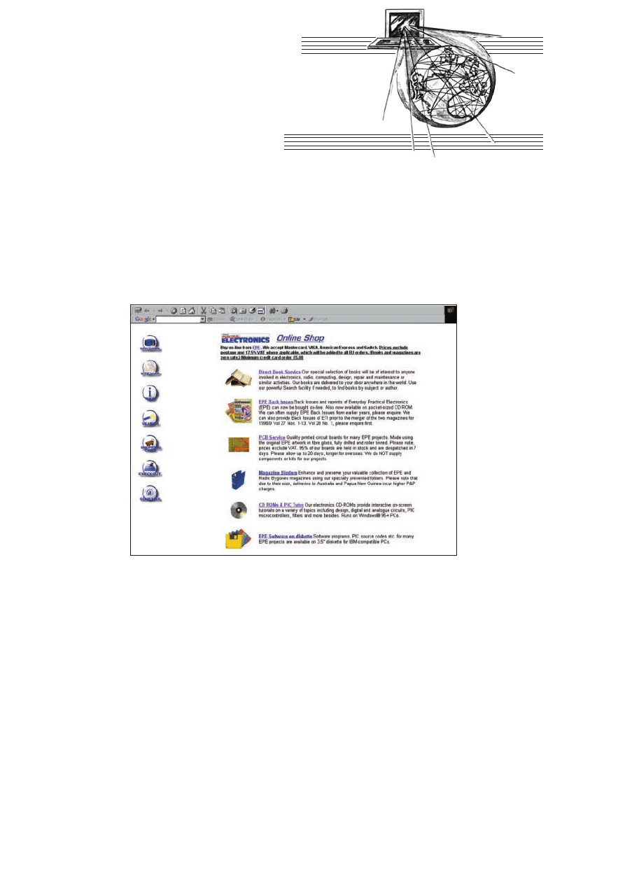
EPE Online Shop
R
EGULAR
users of the EPE web site will know that we recently
launched our new shopping cart service. Now you can purchase
back issues of EPE via the Internet, together with project printed
circuit boards all at the same time. We have also added the entire
range of books from the Direct Book Service, including those spe-
ciality books offered by our sister magazine Radio Bygones. You
can read a comprehensive description of a book’s contents and
usually view a colour image of book and magazine covers. Our
selection of magazine binders, CD ROMs and Ucando videotapes
completes the line up of products available through the new EPE
shopping service.
The system offers
all the usual facilities
that customers would
expect in a compre-
hensive shopping
cart. Each distinct
product area is con-
tained in a “Section”,
and you can easily
navigate around the
shop using the Site
Map if needed. A
powerful search
engine will display
all related products
(e.g. back issues and
c o r r e s p o n d i n g
p.c.b.s) when you
enter a project name
or keyword.
As a further ser-
vice, you can also
order article reprints
from any back issues
of EPE which are
now out of print.
Simply type in the
issue month and arti-
cle name when you do your shopping, and it will be added to your
shopping cart. Then proceed to the checkout when you are finished,
enter your details and payment method, and the order will then be
transmitted securely to the Orders Department for attention.
The new shop is at www.epemag.wimborne.co.uk/shop-
door.htm where you can view service announcements and FAQs,
before entering the secure area itself – the shopping cart is held on
a secure server, and all customer order data is encrypted at all times
for security and peace of mind. Please be aware this is a different
service from our American-based EPE Online (www.epemag.com)
which sells its own range of books and CD ROMs.
Postscript
We have worked hard to bring all those “reader essentials”
together under one roof, so that you can now place a single order to
cover all your requirements. A quick scan through the EPE mail
order advertisements in this issue will show that there is a very wide
variety of electronics-related products available directly from EPE,
including books, videos and CD ROMs as always, but due to the
way that the product range has gradually evolved over the years,
there are a number of different postage rates in force. In fact, it is
calculated that, across the board, there were nearly one hundred
combinations of product and postage available!
Attempting to translate that into a simple on-line shopping cart
service has been challenging to say the least, and ultimately a more
radical approach needed to be adopted. Therefore, there are some
initial differences between our on-line shop and the more tradition-
al mail-order service that EPE will continue to offer.
However, we have attempted to iron out the obvious anomalies in
postage and deliveries by taking an overall “swings and round-
abouts” view. This means we have managed to greatly simplify
things for everybody, while keeping magazine mail-order and on-
line shop prices broadly in line with each other.
As we say in the FAQ, the choice is now yours, but you should
note that prices shown in the on-line shop apply only to Internet
orders. We think that
most customers will
soon prefer the great
convenience of the
on-line shop, but tra-
ditional mail order
coupon, phone or fax
sales will continue to
be available for those
preferring to pur-
chase that way.
A Taxing
Time
For the benefit of
our many overseas
readers,
the most
important difference
is that all “on-line”
prices exclude Value
Added Tax (VAT,
currently 17·5%), as
well as postage
charges. Orders from
customers in all EU
(European Union)
countries will be sub-
jected to VAT, the
value of which will
be clearly shown on the on-line shopping cart. Orders from outside
the EU, are not charged VAT.
Next, postage: all on-line prices exclude postage, as the shopping
cart “knows” the weight of each product (or average weight, in the
case of magazines and p.c.b.s), so the postage cost is calculated on
the total weight of the order. Postage also depends on destination –
we deliver to most countries around the world, and customers out-
side the EU will usually be offered a choice of air or surface mail
deliveries.
We think this is the fairest and most transparent method to imple-
ment. Again, the system is programmed with the postage rates to
each country, and so the postage options are calculated by the shop-
ping cart and clearly shown to the customer.
At all times, you can view your current shopping cart, and
delete or amend products as necessary, and customers will be
able to see the total value of orders, including postage and VAT
where levied, before they decide to enter their payment details
and confirm their order. You will always be offered a comprehen-
sive receipt and order reference number, which you should print
off and keep.
The payment options have also increased: EPE can now accept
Mastercard, VISA, American Express and Switch debit cards (but
not Electron cards). So have a go – buy on-line from EPE!
SURFING THE INTERNET
NET WORK
ALAN WINSTANLEY
286
Everyday Practical Electronics, April 2001
Prices for each of the CD-ROMs above are:
Hobbyist/Student ...................................................£45 inc VAT
Institutional (Schools/HE/FE/Industry)..............£99
plus VAT
Institutional 10 user (Network Licence) ..........£199
plus VAT
Complimentary output stage
Virtual laboratory – Traffic Lights
Digital Electronics builds on the knowledge of logic gates covered in Electronic
Circuits & Components (opposite), and takes users through the subject of
digital electronics up to the operation and architecture of microprocessors. The
virtual laboratories allow users to operate many circuits on screen.
Covers binary and hexadecimal numbering systems, ASCII, basic logic gates,
monostable action and circuits, and bistables – including JK and D-type flip-
flops. Multiple gate circuits, equivalent logic functions and specialised logic
functions. Introduces sequential logic including clocks and clock circuitry,
counters, binary coded decimal and shift registers. A/D and D/A converters,
traffic light controllers, memories and microprocessors – architecture, bus
systems and their arithmetic logic units.
(UK and EU customers add VAT at 17.5% to “plus VAT’’ prices)
Analogue Electronics is a complete learning resource for this most
difficult branch of electronics. The CD-ROM includes a host of virtual
laboratories, animations, diagrams, photographs and text as well as a
SPICE electronic circuit simulator with over 50 pre-designed circuits.
Sections on the CD-ROM include: Fundamentals – Analogue Signals (5
sections),Transistors (4 sections), Waveshaping Circuits (6 sections).
Op.Amps – 17 sections covering everything from Symbols and Signal
Connections to Differentiators. Amplifiers – Single Stage Amplifiers (8
sections), Multi-stage Amplifiers (3 sections). Filters – Passive Filters (10
sections), Phase Shifting Networks (4 sections), Active Filters (6 sections).
Oscillators – 6 sections from Positive Feedback to Crystal Oscillators.
Systems – 12 sections from Audio Pre-Amplifiers to 8-Bit ADC plus a
gallery showing representative p.c.b. photos.
Filters is a complete course in designing active and passive filters that
makes use of highly interactive virtual laboratories and simulations to
explain how filters are designed. It is split into five chapters: Revision which
provides underpinning knowledge required for those who need to design
filters. Filter Basics which is a course in terminology and filter
characterization, important classes of filter, filter order, filter impedance and
impedance matching, and effects of different filter types. Advanced Theory
which covers the use of filter tables, mathematics behind filter design, and
an explanation of the design of active filters. Passive Filter Design which
includes an expert system and filter synthesis tool for the design of low-
pass, high-pass, band-pass, and band-stop Bessel, Butterworth and
Chebyshev ladder filters. Active Filter Design which includes an expert
system and filter synthesis tool for the design of low-pass, high-pass, band-
pass, and band-stop Bessel, Butterworth and Chebyshev op.amp filters.
Digital Works Version 3.0 is a graphical design tool that enables you to
construct digital logic circuits and analyze their behaviour. It is so
simple to use that it will take you less than 10 minutes to make your
first digital design. It is so powerful that you will never outgrow its
capability.
)Software for simulating digital logic circuits
)Create your own macros – highly scalable
)Create your own circuits, components, and i.c.s
)Easy-to-use digital interface
)Animation brings circuits to life
)Vast library of logic macros and 74 series i.c.s with data sheets
)Powerful tool for designing and learning
Counter project
Filter synthesis
ELECTRONICS CD-ROMS
FILTERS
DIGITAL WORKS 3.0
ANALOGUE ELECTRONICS
Logic Probe testing
ELECTRONICS PROJECTS
DIGITAL ELECTRONICS
PRICES
Electronic Projects is split into two main sections: Building Electronic Projects
contains comprehensive information about the components, tools and
techniques used in developing projects from initial concept through to final
circuit board production. Extensive use is made of video presentations showing
soldering and construction techniques. The second section contains a set of ten
projects for students to build, ranging from simple sensor circuits through to
power amplifiers. A shareware version of Matrix’s CADPACK schematic
capture, circuit simulation and p.c.b. design software is included.
The projects on the CD-ROM are: Logic Probe; Light, Heat and Moisture
Sensor; NE555 Timer; Egg Timer; Dice Machine; Bike Alarm; Stereo Mixer;
Power Amplifier; Sound Activated Switch; Reaction Tester. Full parts lists,
schematics and p.c.b. layouts are included on the CD-ROM.
ELECTRONICS
CAD PACK
Electronics CADPACK allows users to
design complex circuit schematics, to view
circuit animations using a unique SPICE-
based simulation tool, and to design
printed circuit boards. CADPACK is made
up of three separate software modules:
ISIS Lite which provides full schematic
drawing features including full control of
drawing appearance, automatic wire
routing, and over 6,000 parts. PROSPICE
Lite (integrated into ISIS Lite) which uses
unique animation to show the operation of
any circuit with mouse-operated switches,
pots. etc. The animation is compiled using
a full mixed mode SPICE simulator. ARES
Lite PCB layout software allows
professional quality PCBs to be designed
and includes advanced features such as
16-layer boards, SMT components, and
even a fully functional autorouter.
“C’’ FOR PICMICRO
MICROCONTROLLERS
C for PICmicro Microcontrollers is
designed for students and professionals
who need to learn how to use C to
program embedded microcontrollers. This
product contains a complete course in C
that makes use of a virtual C PICmicro
which allows students to see code
execution step-by-step. Tutorials, exercises
and practical projects are included to allow
students to test their C programming
capabilities. Also includes a complete
Integrated Development Environment, a full
C compiler, Arizona Microchip’s MPLAB
assembler, and software that will program
a PIC16F84 via the parallel printer port on
your PC. (Can be used with the
PICtutor
hardware – see opposite.)
Although the course focuses on the use of
the PICmicro series of microcontrollers,
this product will provide a relevant
background in C programming for any
microcontroller.
NEW
NEW
PCB Layout

Interested in programming PIC microcontrollers? Learn with
P
PIIC
Cttu
utto
orr
by John Becker
This highly acclaimed CD-ROM, together with the PICtutor experimental and development board, will teach
you how to use PIC microcontrollers with special emphasis on the PIC16x84 devices. The board will also act
as a development test bed and programmer for future projects as your programming skills develop. This
interactive presentation uses the specially developed Virtual PIC Simulator to show exactly what is
happening as you run, or step through, a program. In this way the CD provides the easiest and best ever
introduction to the subject.
Nearly 40 Tutorials cover virtually every aspect of PIC programming in an easy to follow logical sequence.
HARDWARE
Whilst the CD-ROM can be used on its own, the physical demonstration provided by the PICtutor
Development Kit, plus the ability to program and test your own PIC16x84s, really reinforces the lessons
learned. The hardware will also be an invaluable development and programming tool for future work.
Two levels of PICtutor hardware are available – Standard and Deluxe. The Standard unit comes with a battery
holder, a reduced number of switches and no displays. This version will allow users to complete 25 of the 39
Tutorials. The Deluxe Development Kit is supplied with a plug-top power supply (the Export Version has a
battery holder), all switches for both PIC ports plus l.c.d. and 4-digit 7-segment l.e.d. displays. It allows users
to program and control all functions and both ports of the PIC. All hardware is supplied fully built and tested
and includes a PIC16F84.
MODULAR CIRCUIT DESIGN
This CD-ROM contains a range of tried and tested analogue and digital
circuit modules, together with the knowledge to use and interface them.
Thus allowing anyone with a basic understanding of circuit symbols to
design and build their own projects.
Essential information for anyone undertaking GCSE or “A’’ level
electronics or technology and for hobbyists who want to get to grips
with project design. Over seventy different Input, Processor and Output
modules are illustrated and fully described, together with detailed
information on construction, fault finding and components, including
circuit symbols, pinouts, power supplies, decoupling etc.
Single User Version £19.95 inc. VAT
Multiple User Version £34
plus VAT
(UK and EU customers add VAT at 17.5% to “plus VAT’’ prices)
Minimum system requirements for these CD-ROMs: PC with 486/166MHz, VGA+256 colours, CD-ROM drive, 32MB RAM, 10MB hard disk space. Windows 95/98, mouse, sound card, web browser.
CD-ROM ORDER FORM
Electronic Projects
Analogue Electronics
Version required:
Digital Electronics
Hobbyist/Student
Filters
Institutional
Digital Works 3.0
Institutional 10 user
Electronics CAD Pack
C For PICmicro Microcontrollers
PICtutor
Electronic Circuits & Components +The Parts Gallery
PICtutor Development Kit – Standard
PICtutor Development Kit – Deluxe
Deluxe Export
Electronic Components Photos
Modular Circuit Design – Single User
Modular Circuit Design – Multiple User
Full name: . . . . . . . . . . . . . . . . . . . . . . . . . . . . . . . . . . . . . . . . . . . . . . . . . . . . . . . . . . . . . . . . . . . . . .
Address: . . . . . . . . . . . . . . . . . . . . . . . . . . . . . . . . . . . . . . . . . . . . . . . . . . . . . . . . . . . . . . . . . . . . . . . .
. . . . . . . . . . . . . . . . . . . . . . . . . . . . . . . . . . . . . . . . . . . . . . . . . . . . . . . . . . . . . . . . . . . . . . . . . . . . . .
. . . . . . . . . . . . . . . . . . . . . . . . . . . .Post code: . . . . . . . . . . . . . . . .Tel. No: . . . . . . . . . . . . . . . . . . . .
Signature: . . . . . . . . . . . . . . . . . . . . . . . . . . . . . . . . . . . . . . . . . . . . . . . . . . . . . . . . . . . . . . . . . . . . . . .
I enclose cheque/PO in £ sterling payable to WIMBORNE PUBLISHING LTD for £ . . . . . . . . . . . . . .
Please charge my Visa/Mastercard/Switch: £ . . . . . . . . . . . . .Card expiry date: . . . . . . . . . . . . . . . .
Card No: . . . . . . . . . . . . . . . . . . . . . . . . . . . . . . . . . . . . . . . . . . . . . . . . . . . Switch Issue No. . . . . . . .
ORDERING
ALL PRICES INCLUDE UK
POSTAGE
Student/Single User/Standard Version
price includes postage to most
countries in the world
EU residents outside the UK add £5
for airmail postage per order
Institutional,
Multiple User and Deluxe
Versions – overseas readers add £5 to the basic
price of each order for airmail postage (do not
add VAT unless you live in an EU country, then
add 17½% VAT or provide your official VAT
registration number).
Send your order to:
Direct Book Service
Allen House, East Borough, Wimborne
Dorset BH21 1PF
Direct Book Service is a division of Wimborne
Publishing Ltd. To order by phone ring
01202 881749. Fax: 01202 841692
Goods are normally sent within seven days
E-mail: orders@epemag.wimborne.co.uk
The Virtual PIC
Deluxe PICtutor Hardware
Note: The software on each
version is the same, only
the licence for use varies.
Note: The CD-ROM is not included
in the Development Kit prices.
ee50b
ELECTRONIC CIRCUITS & COMPONENTS
+ THE PARTS GALLERY
Provides an introduction to the principles and application of the most common types of
electronic components and shows how they are used to form complete circuits. The
virtual laboratories, worked examples and pre-designed circuits allow students to learn,
experiment and check their understanding. Sections include:
Fundamentals:
units &
multiples, electricity, electric circuits, alternating circuits.
Passive Components:
resistors, capacitors, inductors, transformers.
Semiconductors:
diodes, transistors,
op.amps, logic gates.
Passive Circuits . Active Circuits
The Parts Gallery
will help students to recognise common electronic components and
their corresponding symbols in circuit diagrams. Selections include:
Components,
Components Quiz, Symbols, Symbols Quiz, Circuit Technology
Hobbyist/Student...............................................................................£34 inc VAT
Institutional (Schools/HE/FE/Industry)............................................£89
plus VAT
Institutional 10 user (Network Licence)..........................................£169
plus VAT
(UK and EU customers add VAT at 17.5% to “plus VAT’’ prices)
Note: The software on each version is
the same, only the licence for use varies.
PICtutor CD-ROM
Hobbyist/Student . . . . . . . . . . . . . . . . . . . .£45 inc. VAT
Institutional (Schools/HE/FE Industry) . . .£99
plus VAT
Institutional 10 user (Network Licence) .£199
plus VAT
HARDWARE
Standard PICtutor Development Kit . . . . . . .£47 inc. VAT
Deluxe PICtutor Development Kit . . . . . . . .£99
plus VAT
Deluxe Export Version . . . . . . . . . . . . . . . . .£96
plus VAT
(UK and EU customers add VAT at 17.5% to “plus VAT’’ prices)
ELECTRONIC COMPONENTS PHOTOS
A high quality selection of over 200 JPG images of electronic components. This selection of high resolution photos can be used to enhance projects
and presentations or to help with training and educational material. They are royalty free for use in commercial or personal printed projects, and can
also be used royalty free in books, catalogues, magazine articles as well as worldwide web pages (subject to restrictions – see licence for full details).
Also contains a FREE 30-day evaluation of Paint Shop Pro 6 – Paint Shop Pro image editing tips and on-line help included!
Price
£19.95
inc. VAT
Please send me:
B3
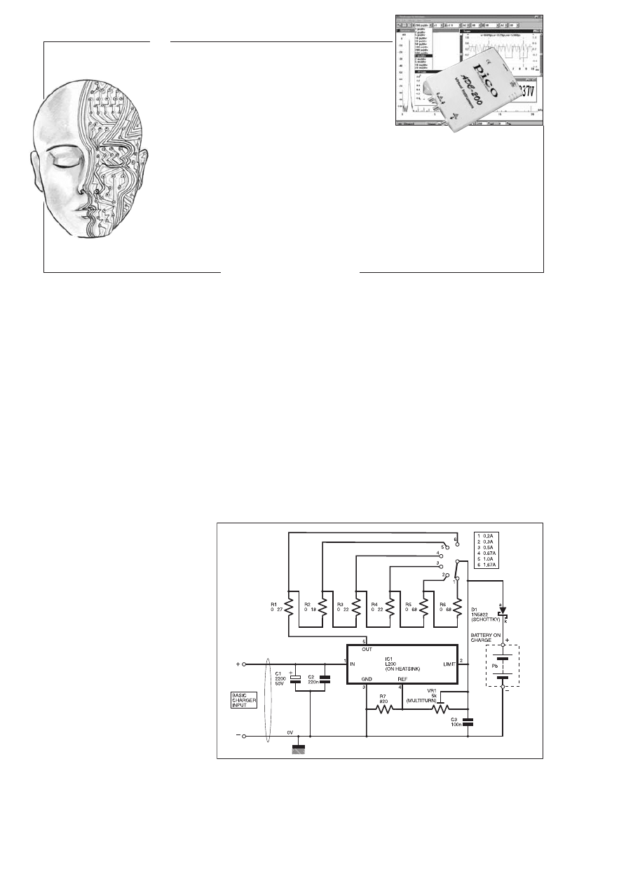
I
NGENUITY
UNLIMITED
Our regular round-up of readers' own circuits. We pay between
£10 and £50 for all material published, depending on length
and technical merit. We're looking for novel applications and
circuit designs, not simply mechanical, electrical or software
ideas. Ideas
must be the reader's own work
and must not
have been submitted for publication elsewhere. The
circuits shown have NOT been proven by us.
Ingenuity
Unlimited
is open to ALL abilities, but items for consideration in
this column should be typed or word-processed, with a brief
circuit description (between 100 and 500 words maximum) and
full circuit diagram showing all relevant component values.
Please draw all circuit schematics as clearly as possible.
Send your circuit ideas to: Alan Winstanley,
Ingenuity
Unlimited,
Wimborne Publishing Ltd., Allen House, East
Borough, Wimborne, Dorset BH21 1PF. (We do not accept
submissions for
IU
via E-mail.)
Your ideas could earn you some cash and a prize!
W
WIIN
N A
A P
PIIC
CO
O P
PC
C B
BA
AS
SE
ED
D
O
OS
SC
CIIL
LL
LO
OS
SC
CO
OP
PE
E
) 50MSPS Dual Channel Storage Oscilloscope
) 25MHz Spectrum Analyser
) Multimeter ) Frequency Meter
)Signal Generator
If you have a novel circuit idea which would be
of use to other readers then a Pico Technology
PC based oscilloscope could be yours.
Every six months, Pico Technology will be
awarding an ADC200-50 digital storage
oscilloscope for the best IU submission. In
addition, two single channel ADC-40s will be
presented to the runners-up.
290
Everyday Practical Electronics, April 2001
12V Sealed Lead/Acid Charger –
C
Cy
yc
clliic
c B
Ba
atttte
er
ry
y U
Us
se
e
C
ONSTRUCTORS
have often been advised
that it is unwise to charge a sealed 12V
lead/acid battery directly from a simple “car
type” charger which usually consists of a
transformer, bridge rectifier and a meter that
gives some indication of the charging current.
There are good reasons for this, including the
fact that a simple car battery charger is not
suitably current limited and can quickly
sizzle a badly discharged sealed lead/acid
battery.
It is recommended that the charging cur-
rent for a sealed lead/acid battery is limited to
25 per cent of the battery’s Ah (Ampere-
Hour) rating. For example, an 8Ah battery
can supply one amp over an eight hour
period, four amps over two hours and eight
amps over one hour and so on.
It is unlikely that the output voltage from a
standard charger is suitable for charging a
12V sealed lead/acid battery. A constant and
stable voltage of between 2·4V and 2·5V per
cell is required for cyclic charging which
equates to 14·4V to 15·0V for a 12V battery.
However, the circuit diagram of Fig.1 shows
a method of charging sealed lead/acid batter-
ies using a basic car battery charger with the
aid of an L200 voltage/current regulator chip.
The off-load output voltage from a typical
basic car battery charger is 13·0V as mea-
sured, which is taken to a 2,200µF 50V elec-
trolytic capacitor C1. This smoothes the
charger output and increases its available d.c.
voltage to just over 20V, providing enough
“headroom” to overcome the voltage drop
across the L200 regulator and diode D1.
On The Limit
The value of the current limiting resistor
(R1 to R6) is determined by measuring the
open circuit voltage across pins 2 and 5 of the
L200 (with power applied to its input). This is
the reference voltage and should be in the
region of 450mV which is divided by the
required output current (2·0A maximum). For
example, V
ref
/required current = 0·45/0·2
(200mA) = 2·25 ohms.
The output of the charger has an
adjustable current limit, consisting of six
low value resistors wired to a 1-pole 6-way
wafer switch. This enables the current to
be reduced, enabling a good range of
sealed lead/acid batteries to be charged.
The resistor/switch combination is con-
nected between pin 2 and pin 5 using short
leads.
The diode D1 prevents any current flowing
from the battery being charged, through the
potential divider (R7 and VR1) should the
charging source be removed with the battery
connected. With the selected current limit
resistor in circuit and power applied to the
input of the regulator IC1, adjust VR1 for a
voltage of between 14·4V to 15·0V as mea-
sured between the cathode (k) of diode D1
and 0V line.
When the above adjustments are complete
the battery may be connected and the charger
switched on and left as the battery will auto-
matically draw less current as it reaches its
charged state. A full charge should take about
10 to 14 hours.
This can be monitored by the ammeter of
the battery charger, but a more accurate
method is to monitor the voltage across the
current limiting resistor using an external
voltmeter. The actual charging current can
then be determined by the application of
Ohm’s Law, i.e. the voltage across the
switched resistor network / the value of resis-
tance in ohms.
(Readers wanting to know more about the
L200 should check Andy Flind’s feature arti-
cle “Using The L200CV’’ in EPE July 1998 –
ARW).
David Allen,
Cheltenham, Glocs.
Ω
Ω
Ω
Ω
Ω
Ω
Ω
µ
FIg.1. Circuit diagram for the 12V Sealed Lead/Acid Charger. (The low-ohm
resistors (R1 to R6) can be from the W21 series.)
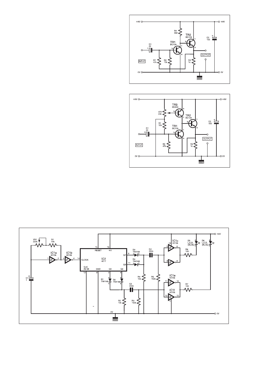
Everyday Practical Electronics, April 2001
291
Audio Preamplifier –
S
So
om
me
e G
Ga
aiin
n
A
SIMPLE
preamplifier was needed to drive a rather insensitive
audio amplifier which required about 500mV peak-to-peak
input to obtain a reasonable output. Unfortunately, the source (a
rather old guitar pickup) did not deliver much in the way of
drive, being only a few millivolts. Using a design that was found
to be reliable in the past (a d.c. coupled configuration with an
emitter follower output – see Fig. 2a), did not produce nearly
enough drive, the voltage gain being in the order of about 100
times.
The first stage of the preamp produces all the voltage gain and is
proportional to transistor TR1’s load resistor, in this case 6k8 (R4).
Increasing the value of this resistor to increase the amplifier gain
is, of course, possible, but it was estimated that it would need to be
increased by approximately 4 or 5 times.
New Addition
This would restrict the current in TR1 to a few tenths of a mil-
liamp, severely curtailing its gain and defeating the object. This
called for a different approach and the result is shown in Fig.2b.
The original 6k8 load resistor was replaced with a transistor
(TR3), the object here being twofold: firstly TR3 can be biased to
restore the original d.c. conditions, i.e. TR1 will now pass the cur-
rent originally intended (about 0·7mA).
Second, and most importantly, the load seen by TR1 will now be
the a.c. resistance of TR3, which is considerably higher than its
d.c. resistance. Therefore, TR1 now sees the output impedance of
TR3, and TR1’s amplification factor is boosted.
To set up the d.c. conditions, adjust the 20 kilohm (more likely
to be 22k) variable potentiometer VR1 so that about 4·5V appears
on the collector (c) of transistor TR1. If you require a gain control,
then a small potentiometer of about 100 kilohms can be connected
at the input side of capacitor C1.
The circuit worked well and produced a voltage gain in excess
of 600 times, along with good temperature stability – more than
adequate for the purpose in hand.
A. Lippett,
Stafford.
µ
µ
µ
µ
Fig.2a. Original basic preamplifier circuit.
Fig.2b. Circuit diagram for the simple Audio Preamplifier.
µ
Ω
Ω
Fig.3. Circuit diagram for a Model Police Car L.E.D.s (Fuzzlite) simulator.
M
Y
youngest child (aged 8) loves police
cars, but his attempts to add blue l.e.d.s
to model police cars were simply not realistic
enough for the discerning junior enthusiast.
So the circuit of Fig.3 was devised to simu-
late the alternate flashing strobes seen on
British police cars. This was well received,
and now many of these circuits have been
built and look very convincing indeed in the
dark!
The circuit around ICla forms a square
wave oscillator,
the frequency being
adjustable by VR1 to give the best effect.
This square wave is buffered by 1C1b and in
turn drives the decade counter IC2. Outputs
from the counter Q0/Q2, and Q7/Q9 are in
turn diode ORed to give alternating double
pulses.
Capacitors C2 and C3 with resistors R3 and
R5 differentiate the pulse time in conjunction
with the output drivers 1C1c to ICIf. This pro-
duces a short pulse (30ms) which enhances the
flashing effect and adds to the illusion. The out-
put drivers in turn drive a pair of hyperbright
blue l.e.d.s D5 and D6.
It is worth spending a little extra on using
really bright l.e.d.s if the best effect is to be
obtained. A 6V camera battery or four AAA
cells gives a long life in a small package. In
use adjust VR1 to give the best effect.
Kate Turner,
St. Leonards on Sea, East Sussex.
Model Police Car L.E.D.s –
IIn
n A
A F
Flla
as
sh
h
IC1d
40106
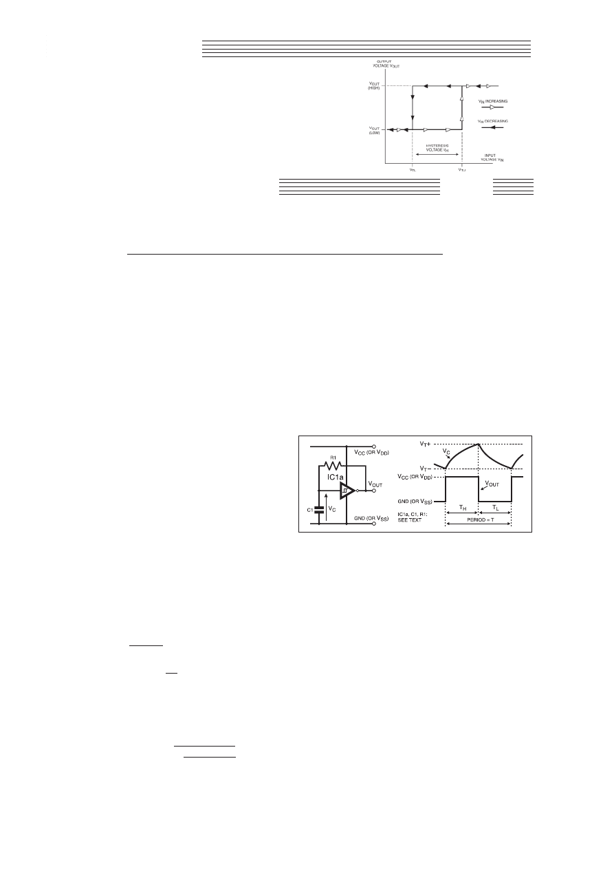
I
N Part Five of this series we saw how ‘‘digital’’ Schmitt trigger
devices from the 4000 series and 74HC/HCT logic families
could be used both as interface components, and also as the
active elements in various other functions. This month, we’ll exam-
ine another important interface circuit, the contact debouncer, and
we’ll see how the Schmitt’s unique behaviour can be put to use in a
variety of oscillator and modulator circuits. We’ll also see how the
Schmitt can be used in more complex functions such as a frequency
meter and a clock pulser.
ASTABLE MULTIVIBRATOR
We will start by examining the Schmitt’s role in what is, perhaps,
its simplest application – the astable multivibrator, or square wave
oscillator. The basic circuit and its associated waveforms are shown
in Fig.6.1, where IC1a could be a Schmitt inverter from the 40106B
or 74HC/HCT14, or could be a 2-input Schmitt NAND from the
4093B or 74HC/HCT132 (if a NAND is used, one of the two inputs
should be tied high, the other connected to capacitor C1 and resis-
tor R1 as shown).
During period T
H
when the output, V
OUT
, is high, V
C
(the voltage
across C1) rises exponentially as C1 charges via R1. Eventually,
when V
C
reaches the Schmitt’s positive-going threshold voltage,
V
T+
, the output rapidly changes state and goes low.
Capacitor C1 now begins to discharge via R1, and during period
T
L
the capacitor voltage V
C
decreases exponentially until it reaches
the negative-going threshold voltage, V
T–
. At this point, V
OUT
goes
high again, and the process repeats, producing a rectangular output
signal with period T = T
H
+ T
L
.
HITTING THE RAILS
The output voltage of CMOS logic devices from the 4000 series
and 74HC/HCT family will swing from the negative to the positive
supply rail, provided the output is not excessively loaded. The actu-
al output characteristics vary from one type of device to another, but
as a rule of thumb we can assume the output will swing rail-to-rail
if the output current is kept below ±100µA. Consequently, for a
lightly loaded output, the time periods T
H
and T
L
are given by:
T
H
=
J ln
V
CC
– V
T–
(seconds)
{
V
CC
– V
T+
}
and:
T
L
=
J ln
V
T+
{
V
T–
}
where
J is the circuit time constant, J = C1 × R1, and ln denotes the
natural logarithm. V
CC
is the positive supply voltage (usually denot-
ed V
DD
for the 4093B and 40106B).
The frequency of oscillation, F
OUT
, is given by:
F
OUT
= 1/T = 1/(T
H
+ T
L
) =
1
(Hz)
J ln V
T+
(V
CC
– V
T–
)
V
T–
(V
CC
– V
T+
)
The expressions for F
OUT
, T
H
and T
L
will provide accurate results
provided T
H
and T
L
are much larger than the propagation delays of
the device used for IC1a. Therefore, for the 74HC14 and 74HC132,
the equations will be accurate up to an operating frequency of about
5MHz; for the 4093B and 40106B, the expressions hold true to
about 500kHz.
The astable in Fig.6.1 was built using a 74HC14 inverter for
IC1a, and values of 1nF and 100k
9 were selected for C1 and R1,
giving a time constant
J = 100µs. With the supply voltage, V
CC
, set
to 5V, the switching thresholds were measured as V
T–
= 1·68V and
V
T+
= 2·70V. Using these values in the timing equations above, we
find that T
H
= 36·7µs, T
L
= 47·4µs, and F
OUT
= 11,883Hz. The
actual, measured values were T
H
= 38·9µs, T
L
= 48·4µs and F
OUT
=
11,455Hz.
A STABLE ASTABLE
Like the pulse stretchers described last month, the astable oscillator
is highly tolerant of changes in supply voltage. For applications
where V
CC
(or V
DD
) is not regulated, such as simple battery-powered
circuits, F
OUT
would, ideally, remain constant as the voltage changes.
In this respect, the simple astable performs well.
For example, with the supply voltage decreased by 20 per cent
from 5V to 4V, the test circuit’s output frequency decreased by only
7·5% to 10,593Hz. With V
CC
increased by 20 per cent from 5V to
6V, F
OUT
was found to increase by just 5·3% to 12,063Hz.
The frequency stability was even better when the 74HC14 was
replaced by a 40106B. With the same timing components and a 5V
supply, the output frequency was 12,953Hz. With the supply
increased by 200 per cent to 15V, the increase in F
OUT
was only 6·8
per cent! Although the Schmitt-based astable can never compete
with a crystal-based oscillator in terms of frequency stability, the
performance is remarkably good considering its inexpensive
simplicity.
CHOICE OF COMPONENTS
When selecting suitable values for the timing components of
Fig.6.1, capacitor C1 should not be too small, otherwise the pres-
ence of stray capacitance, together with IC1a’s input capacitance,
SSppeecciiaall SSeerriieess
THE SCHMITT
TRIGGER
In this short series, we investigate the Schmitt trigger’s operation; explore the various
ways of implementing its special characteristics and also look at how we can use it to
create oscillators and pulse width modulators.
Further Digital Applications
Everyday Practical Electronics, April 2001
293
ANTHONY H. SMITH
Part 6
Fig.6.1. Astable multivibrator circuit diagram and waveforms.
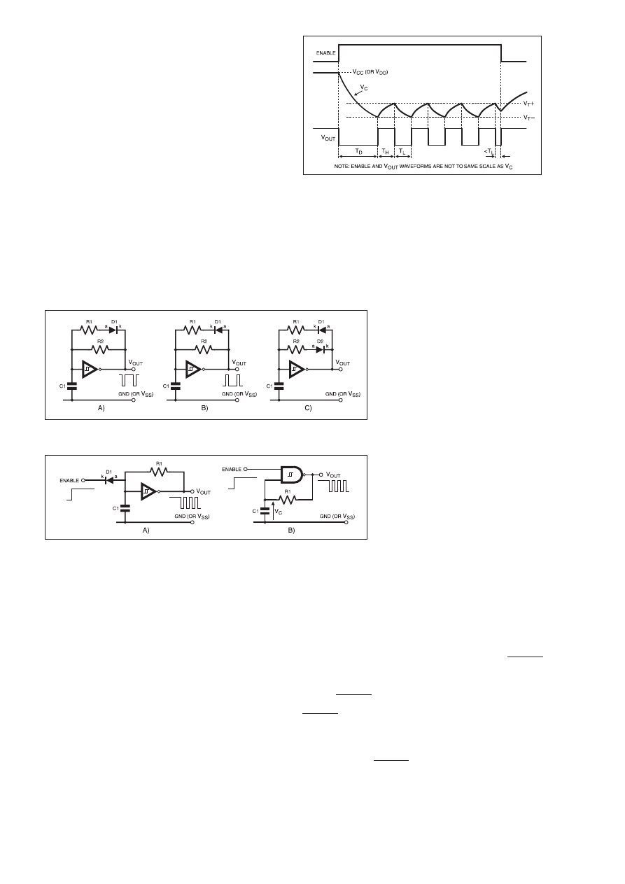
will have a noticeable effect on the values of T
H
and T
L
. Generally,
these additional (and somewhat unpredictable) capacitances will
have negligible effect if C1 is greater than 100pF. There is no upper
limit on the value of C1: values of several hundred microfarads can
be used where a large time constant is required.
Remember that resistor R1 acts as a load on the output (together
with any other load), so small values of timing resistor should be
avoided or the output will not swing rail-to-rail. In most cases, R1
should be no less than ten kilohms (10k
9), although lower values
may be used if high frequency operation (i.e., small
J) is required.
Where practicable, values of 100k
9 or more will give best results.
The upper limit is around one megohm (1M
9); larger values should
be used with caution, since IC1a’s input current may have unpre-
dictable effects on the values of T
H
and T
L
.
Power consumption is also affected by the choice of C1 and R1.
For example, with C1 at 100pF and R1 at 100k
9, giving a time con-
stant
J = 10µs, the test circuit described above oscillated at 117kHz,
and the supply current was 576µA.
However, with C1 increased to 10nF and R1 reduced to 1k
9,
again giving a time constant
J = 10µs, the circuit oscillated at rough-
ly the same frequency (107kHz), but the supply current had
increased by almost 200 per cent to 1·68mA. Clearly, the larger
value of C1 means that more energy is required to charge and dis-
charge the capacitor, resulting in greater power consumption.
VARIATIONS ON A THEME
By adding an extra resistor and one or two diodes, the astable can
be adapted to produce different waveforms as shown in Fig.6.2.
In Fig.6.2a, resistor R1 now appears in series with a diode D1,
and a second timing resistor R2 is fitted in parallel with them. When
the output is high, D1 is reverse biased, blocking any current flow
through R1, and capacitor C1 charges via R2 only. However, when
V
OUT
goes low, diode D1 now becomes forward biased, allowing
current to flow through resistor R1. Consequently, C1 discharges
through the parallel combination of R1 and R2, and as a result,
period T
L
can be made much shorter than T
H
.
Diode D1 has been reversed in Fig.6.2b, such that C1 charges via
R1 in parallel with R2 when V
OUT
is high, but discharges only via
R2 when V
OUT
goes low. Therefore, period T
H
can be made much
shorter than T
L
.
The circuits of Fig.6.2a and Fig.6.2b allow for adjustment of the
output duty cycle, and can be used to generate a train of narrow neg-
ative-going or positive-going pulses, respectively. However, they
have the disadvantage that one of the output periods is affected by
changes in the other.
By adding a second diode (D2) as shown in Fig.6.2c, T
H
and T
L
can be adjusted completely independently of each other. In this cir-
cuit, C1 charges only via R1 and discharges only via R2. Therefore,
the width of T
H
can be adjusted by varying the value of resistor R1
without affecting T
L
, and T
L
can be adjusted by varying R2 with no
effect on T
H
.
GATED OSCILLATORS
Two methods for ‘‘gating’’ an astable oscillator are illustrated in
Fig.6.3. In both cases, the astable starts to oscillate when the
ENABLE signal goes high, and oscillation stops when ENABLE
goes low. Being able to gate the astable is a common circuit require-
ment, either for functional reasons, or as a means of saving power.
In Fig.6.3a, a low level at the ENABLE input forward biases
diode D1, thereby clamping the voltage on capacitor C1 to a diode
drop above GND (or V
SS
). Since this is below the inverter’s nega-
tive-going threshold voltage, V
T–
, the output is forced high.
However, when ENABLE goes high, D1
becomes reverse biased allowing C1 to charge
via R1. The astable is now free to oscillate. If
the ‘‘direction’’ of D1 is reversed, the astable
will run when the gating signal is low, and
will stop when it goes high.
The alternative circuit shown in Fig.6.3b
does not require a diode, and instead makes
use of the NAND function provided by a
74HC132 or 4093B. When ENABLE is low,
the NAND output is forced high, and C1
charges via R1 until V
C
equals the high level
output voltage, namely V
CC
(or V
DD
) when the
output is lightly loaded.
When ENABLE goes high, the NAND out-
put is forced low and C1 starts to discharge
via R1. The circuit now behaves like the sim-
ple, inverter-based astable described above,
with capacitor C1 charging and discharging
repeatedly. Exactly the same expressions are
used to determine T
L
, T
H
and F
OUT
.
TRUNCATION
Typical waveforms for the NAND gated
astable are shown in Fig.6.4. As soon as
ENABLE goes high, V
OUT
goes low and there
follows a delay, T
D
, while V
C
decays expo-
nentially toward V
T–
. Proper oscillation then
commences, with V
C
rising and falling between the two switching
thresholds, and the circuit continues to oscillate until ENABLE
goes low.
However, if ENABLE goes low part way through a low period
(T
L
) as shown, V
OUT
is immediately forced high, thereby shortening
the low pulse. This asynchronous behaviour ‘‘truncates’’ the period
of the last cycle.
For applications where this is unacceptable, the addition of a sec-
ond NAND gate as shown in Fig.6.5 can be used to eliminate the
truncation completely. The two, cross-coupled NAND gates func-
tion as an S-R (set-reset) latch, where the active low ENABLE
signal provides the ‘‘set’’ input, and the timing capacitor voltage,
V
C
, constitutes the ‘‘reset’’ input. We can understand how the circuit
works by referring to the waveforms in Fig.6.6.
While ENABLE is high, IC1a’s output, V
OUT
(a), is forced low,
preventing the astable formed around IC1b from oscillating. When
ENABLE goes low, V
OUT
(a) goes high, allowing the astable to run.
IC1b’s output, V
OUT
(b), now oscillates at a frequency F
OUT
as
determined by the equation given earlier. So far, the circuit behaves
in exactly the same manner as the single NAND astable described
earlier.
However, should ENABLE go high during one of V
OUT
(b)’s low
periods as shown, the last cycle is not truncated. It is only when
294
Everyday Practical Electronics, April 2001
Fig.6.2. Circuit variations on the astable multivibrator.
Fig.6.3. Two methods of “gating’’ an astable oscillator.
Fig.6.4. Typical waveforms for the NAND gated astable.
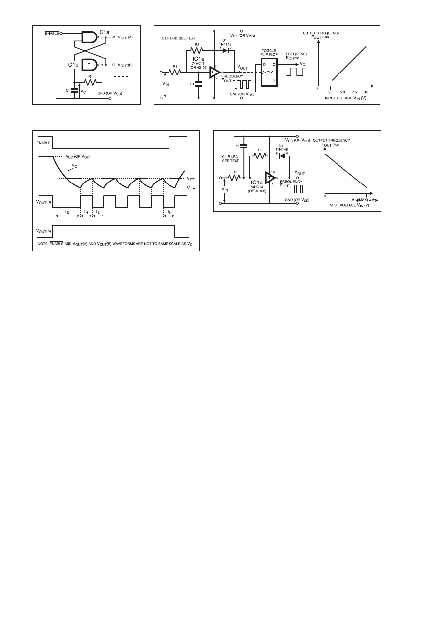
V
OUT
(b) goes high at the end of the low period (T
L
) that V
OUT
(a)
goes low (since IC1a’s inputs are now both high), thereby disabling
the astable. Although the circuit still exhibits a delay, T
D
, when first
enabled, the last cycle is never truncated and the astable always out-
puts a series of whole cycles.
If the gating signal is a ‘‘proper’’ digital signal, IC1a does not
need to be a Schmitt NAND. However, it is often convenient to use
two NANDs from the same Schmitt package, such as a 74HC132 or
4093B.
VOLTAGE CONTROLLED OSCILLATOR
By adding an extra resistor and a diode, the simple astable of
Fig.6.1 can be converted to a voltage controlled oscillator, or v.c.o.,
as shown in Fig.6.7, where the input voltage, V
IN
, is a d.c. voltage
that can take any value from V
T–
to more than 20V.
To understand how the circuit works, assume that V
OUT
is high
such that diode D1 is reverse biased. Timing capacitor C1 charges
via resistor R1, and the capacitor voltage rises exponentially toward
the value of V
IN
.
However, when the voltage on C1 reaches IC1a’s positive-going
threshold voltage, V
T+
, V
OUT
goes low, forward biasing D1, and C1
starts to discharge via R2 and D1. The capacitor voltage now
decreases exponentially; when it reaches IC1a’s negative-going
threshold voltage, V
T–
, V
OUT
goes high, reverse biasing D1, and C1
is now free to charge up again via R1.
Provided resisitor R2 is smaller than R1, the resulting output sig-
nal is a series of negative-going pulses of constant width, defined
only by IC1a’s thresholds, C1, R2 and V
D
, the voltage drop across
diode D1. However, the width of the positive-going portion of V
OUT
depends on IC1a’s thresholds, C1, R1 and V
IN
. Since input voltage
V
IN
is variable, the period of the output signal, and hence the output
frequency, will change with V
IN
. As V
IN
is increased, C1 charges
more quickly causing the output period to decrease, and the fre-
quency increases as shown by the graph.
Note that V
IN
can exceed the positive supply voltage, V
CC
(or
V
DD
). The maximum value is determined by the ratio of resistor R1
to R2. When V
OUT
goes low, R1 and R2 form a potential divider
which ‘‘pulls down’’ the voltage on C1. If V
IN
is too high, the
divider will be unable to pull the capacitor voltage below V
T–
, in
which case V
OUT
will remain continually low.
When V
OUT
is high and D1 is reverse biased, C1 charges only via
R1. Therefore, in order for the capacitor voltage to cross IC1a’s
positive-going threshold, V
IN
must be
³ V
T+
. This establishes the
lower limit for the input voltage.
LINEAR RELATIONSHIP
The performance of the circuit shown in Fig.6.7 was tested using
an inverter from the 74HC14 for IC1a (although any other Schmitt
device could be used). Values of R1 = 100k
W, R2 = 3·3kW, and C1
= 1nF were chosen for the timing components.
With a supply voltage of 5V, the positive-going threshold voltage,
V
T+
, was measured as 2·75V. Therefore, it was decided to set the
input voltage’s (V
IN
) lower limit to 3·0V. The upper limit of V
IN
, at
which V
OUT
went continually low, was found to be 35·6V, although
the circuit’s response had become highly non-linear below this
value.
The relationship between output frequency, F
OUT
, and V
IN
was
found to be very linear for an input voltage of 3·0V to 5·0V, and
reasonably linear over the range of 5·0V to 10·0V. Beyond this, the
relationship deteriorated, with the graph starting to curve signifi-
cantly for values of V
IN
above 15V. The useful operating range was
V
IN
= 3·0V to 10·0V, corresponding to an output frequency range of
6·0kHz to 62·4kHz.
By feeding the v.c.o. output to a toggle-connected flip-flop as
shown in Fig.6.7, a squarewave output can be obtained at V
Q
hav-
ing a constant 50 per cent duty cycle at all frequencies. However,
note that the frequency at V
Q
will be half that at V
OUT
.
INVERSE RELATIONSHIP
By connecting capacitor C1 to the positive supply (V
CC
) and
reversing the ‘‘direction’’ of diode D1 as shown in Fig.6.8, we
obtain a v.c.o. which has an inverse relationship between V
IN
and
F
OUT
, that is, F
OUT
decreases as V
IN
is increased. To understand the
circuit’s behaviour, assume that input voltage V
IN
= 0, and V
OUT
is
low such that D1 is reverse biased.
Capacitor C1 charges up via resistor R1, causing the voltage
across C1 to increase exponentially. Consequently, the voltage at
IC1a’s input decreases exponentially. Eventually, when this voltage
reaches IC1a’s negative-going threshold voltage, V
T–
, V
OUT
goes
high, forward biasing D1.
Capacitor C1 now starts to discharge via R2 and D1, causing the
voltage at IC1a’s input to rise exponentially. The rate at which C1
discharges is determined by the supply voltage V
CC
, by IC1a’s
thresholds, by the values of C1, R1, R2, and by V
IN
and V
D
, the volt-
age drop across D1. However, if R1 is much larger than R2, input
voltage V
IN
will have little effect on the rate of C1’s discharge
which will be controlled mainly by resistor R2.
When IC1a’s input voltage reaches the positive-going threshold
voltage, V
T+
, V
OUT
goes low. Therefore, the output signal consists of
Everyday Practical Electronics, April 2001
295
Fig.6.5. Adding a second NAND gate
eliminates pulse truncation.
Fig.6.7. Adapting the astable to form a voltage controlled oscillator (v.c.o.).
Fig.6.6. Typical waveform for the dual NAND gated astable
circuit of Fig.6.5.
Fig.6.8. Circuit for a voltage controlled oscillator with an
inverse voltage/frequency characteristic.

V
OUT
(b) goes high at the end of the low period (T
L
) that V
OUT
(a)
goes low (since IC1a’s inputs are now both high), thereby disabling
the astable. Although the circuit still exhibits a delay, T
D
, when first
enabled, the last cycle is never truncated and the astable always out-
puts a series of whole cycles.
If the gating signal is a ‘‘proper’’ digital signal, IC1a does not
need to be a Schmitt NAND. However, it is often convenient to use
two NANDs from the same Schmitt package, such as a 74HC132 or
4093B.
VOLTAGE CONTROLLED OSCILLATOR
By adding an extra resistor and a diode, the simple astable of
Fig.6.1 can be converted to a voltage controlled oscillator, or v.c.o.,
as shown in Fig.6.7, where the input voltage, V
IN
, is a d.c. voltage
that can take any value from V
T–
to more than 20V.
To understand how the circuit works, assume that V
OUT
is high
such that diode D1 is reverse biased. Timing capacitor C1 charges
via resistor R1, and the capacitor voltage rises exponentially toward
the value of V
IN
.
However, when the voltage on C1 reaches IC1a’s positive-going
threshold voltage, V
T+
, V
OUT
goes low, forward biasing D1, and C1
starts to discharge via R2 and D1. The capacitor voltage now
decreases exponentially; when it reaches IC1a’s negative-going
threshold voltage, V
T–
, V
OUT
goes high, reverse biasing D1, and C1
is now free to charge up again via R1.
Provided resisitor R2 is smaller than R1, the resulting output sig-
nal is a series of negative-going pulses of constant width, defined
only by IC1a’s thresholds, C1, R2 and V
D
, the voltage drop across
diode D1. However, the width of the positive-going portion of V
OUT
depends on IC1a’s thresholds, C1, R1 and V
IN
. Since input voltage
V
IN
is variable, the period of the output signal, and hence the output
frequency, will change with V
IN
. As V
IN
is increased, C1 charges
more quickly causing the output period to decrease, and the fre-
quency increases as shown by the graph.
Note that V
IN
can exceed the positive supply voltage, V
CC
(or
V
DD
). The maximum value is determined by the ratio of resistor R1
to R2. When V
OUT
goes low, R1 and R2 form a potential divider
which ‘‘pulls down’’ the voltage on C1. If V
IN
is too high, the
divider will be unable to pull the capacitor voltage below V
T–
, in
which case V
OUT
will remain continually low.
When V
OUT
is high and D1 is reverse biased, C1 charges only via
R1. Therefore, in order for the capacitor voltage to cross IC1a’s
positive-going threshold, V
IN
must be
³ V
T+
. This establishes the
lower limit for the input voltage.
LINEAR RELATIONSHIP
The performance of the circuit shown in Fig.6.7 was tested using
an inverter from the 74HC14 for IC1a (although any other Schmitt
device could be used). Values of R1 = 100k
W, R2 = 3·3kW, and C1
= 1nF were chosen for the timing components.
With a supply voltage of 5V, the positive-going threshold voltage,
V
T+
, was measured as 2·75V. Therefore, it was decided to set the
input voltage’s (V
IN
) lower limit to 3·0V. The upper limit of V
IN
, at
which V
OUT
went continually low, was found to be 35·6V, although
the circuit’s response had become highly non-linear below this
value.
The relationship between output frequency, F
OUT
, and V
IN
was
found to be very linear for an input voltage of 3·0V to 5·0V, and
reasonably linear over the range of 5·0V to 10·0V. Beyond this, the
relationship deteriorated, with the graph starting to curve signifi-
cantly for values of V
IN
above 15V. The useful operating range was
V
IN
= 3·0V to 10·0V, corresponding to an output frequency range of
6·0kHz to 62·4kHz.
By feeding the v.c.o. output to a toggle-connected flip-flop as
shown in Fig.6.7, a squarewave output can be obtained at V
Q
hav-
ing a constant 50 per cent duty cycle at all frequencies. However,
note that the frequency at V
Q
will be half that at V
OUT
.
INVERSE RELATIONSHIP
By connecting capacitor C1 to the positive supply (V
CC
) and
reversing the ‘‘direction’’ of diode D1 as shown in Fig.6.8, we
obtain a v.c.o. which has an inverse relationship between V
IN
and
F
OUT
, that is, F
OUT
decreases as V
IN
is increased. To understand the
circuit’s behaviour, assume that input voltage V
IN
= 0, and V
OUT
is
low such that D1 is reverse biased.
Capacitor C1 charges up via resistor R1, causing the voltage
across C1 to increase exponentially. Consequently, the voltage at
IC1a’s input decreases exponentially. Eventually, when this voltage
reaches IC1a’s negative-going threshold voltage, V
T–
, V
OUT
goes
high, forward biasing D1.
Capacitor C1 now starts to discharge via R2 and D1, causing the
voltage at IC1a’s input to rise exponentially. The rate at which C1
discharges is determined by the supply voltage V
CC
, by IC1a’s
thresholds, by the values of C1, R1, R2, and by V
IN
and V
D
, the volt-
age drop across D1. However, if R1 is much larger than R2, input
voltage V
IN
will have little effect on the rate of C1’s discharge
which will be controlled mainly by resistor R2.
When IC1a’s input voltage reaches the positive-going threshold
voltage, V
T+
, V
OUT
goes low. Therefore, the output signal consists of
Everyday Practical Electronics, April 2001
295
Fig.6.5. Adding a second NAND gate
eliminates pulse truncation.
Fig.6.7. Adapting the astable to form a voltage controlled oscillator (v.c.o.).
Fig.6.6. Typical waveform for the dual NAND gated astable
circuit of Fig.6.5.
Fig.6.8. Circuit for a voltage controlled oscillator with an
inverse voltage/frequency characteristic.
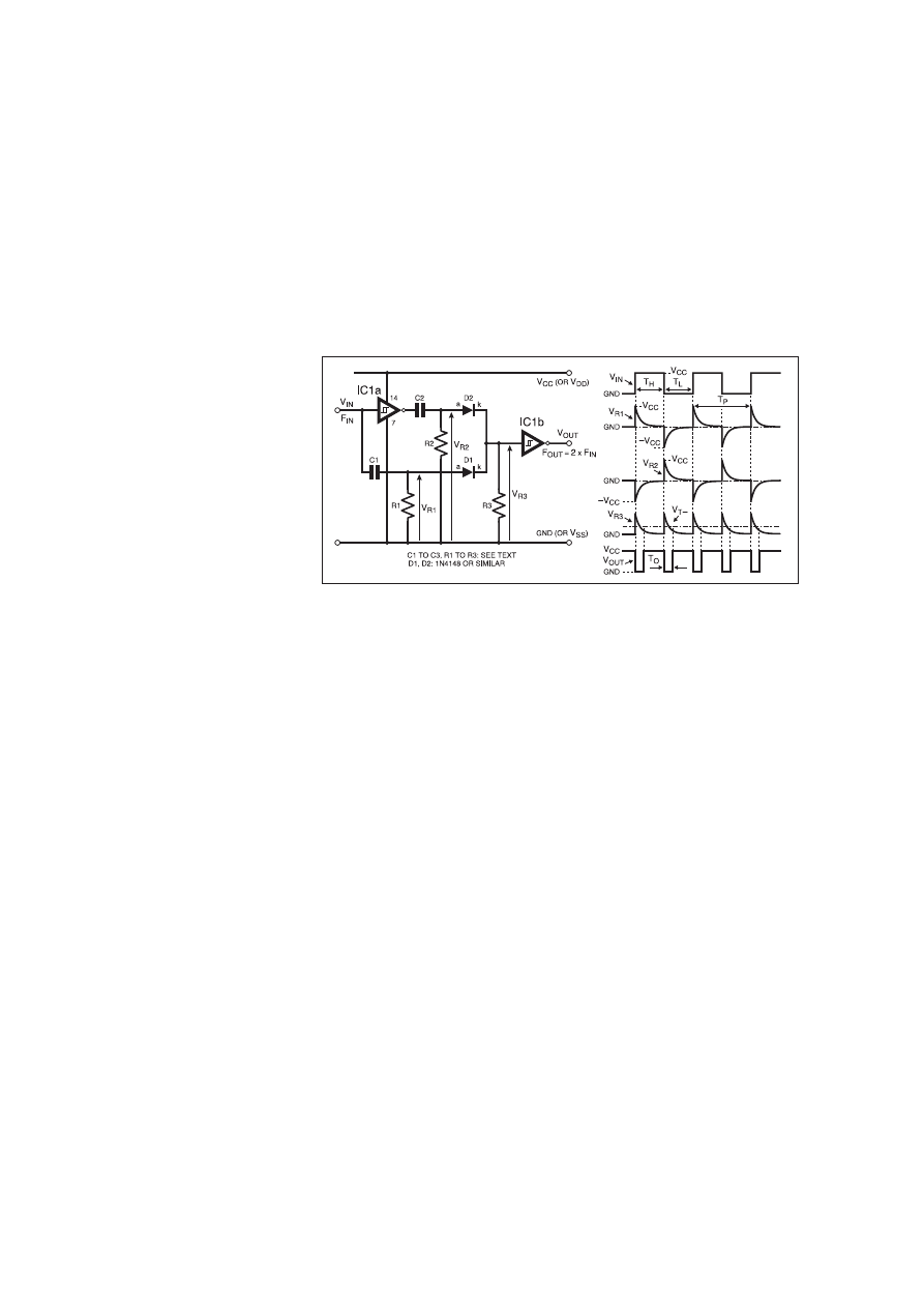
a train of positive-going pulses of almost constant width. Since
V
OUT
is now low, capacitor C1 is free to charge up again via R1 at
a rate determined by V
IN
.
If V
IN
is at a low level, the voltage drop across R1 – and hence
the current through it – will be relatively large, causing C1 to charge
rapidly. In turn, this causes the negative-going portion of the output
signal to be relatively short, resulting in a high frequency.
On the other hand, if V
IN
is at a high level, C1’s charging current
will be relatively small, and it will take longer for IC1a’s input volt-
age to fall to V
T–
. Therefore, the negative-going portion of the out-
put signal to be relatively long, resulting in a low frequency.
Therefore, the output frequency decreases as V
IN
is increased.
INPUT VOLTAGE CONSTRAINTS
The upper limit of V
IN
is determined by IC1a’s negative-going
threshold voltage, V
T–
: if V
IN
exceeds V
T–
, it will be impossible for
the inverter’s input voltage to go below this threshold, and the out-
put will go continually low.
For a single-rail supply circuit, V
IN
’s lower limit is simply zero
(i.e., GND or V
SS
). However, if a negative supply is available, V
IN
may be taken negative (that is, V
IN
may go below GND or V
SS
). The
maximum negative limit is determined by V
CC
(or V
DD
), V
D
, V
T+
and by the ratio of resistor
R1 to R2, since when V
OUT
is high it must be
possible for the R1/R2 potential divider to pull
the inverter’s input voltage above V
T+
.
Provided these constraints are met, the cir-
cuit of Fig.6.8 will produce a fairly linear,
inverse relationship between V
IN
and F
OUT
. A
test circuit was built using an inverter from the
40106B; V
DD
was set to 15·00V, resulting in
thresholds of V
T–
= 5·75V and V
T+
= 8·45V.
Therefore, the maximum value of V
IN
is 5·75V.
With values of R1 = 100k
9, R2 = 3·3k9,
and C1 = 1nF chosen for the timing compo-
nents, the circuit performed well with input
voltages (V
IN
) of 0V to 5·5V, producing a cor-
responding output frequency (F
OUT
) range of
2·5kHz to 410Hz.
FREQUENCY BY THE
DOUBLE!
When clocked by a periodic input signal, the toggle-connected
flip-flop mentioned above provides a simple means of halving the
clock frequency and producing an output signal with a constant 50
per cent duty cycle.
However, in cases where it is necessary to double a signal’s fre-
quency, some other technique must be used. A solution which
makes use of the ‘‘digital differentiator’’ techniques introduced last
month is shown in Fig.6.9.
The logic level input signal, V
IN
, is applied to inverter IC1a, and
also to the C1/R1 differentiator network. IC1a’s output is fed to a
similar differentiator, C2/R2. The differentiated signals V
R1
and V
R2
appearing across resistors R1 and R2 are rectified by diodes D1 and
D2 and the resulting unipolar signals are combined at the input to
IC1b.
The circuit’s operation is illustrated by the accompanying wave-
forms. The rising edge of V
IN
is differentiated by C1/R1, producing
a positive-going, exponential ‘‘spike’’ across R1, having a peak
value equal to V
CC
. The inverted version of V
IN
at IC1a’s output (not
shown) is differentiated by C2/R2, producing a negative-going,
exponential spike across R2, having a peak value equal to –V
CC
.
On the falling edge of V
IN
, the polarities of the spikes are
reversed: V
R1
swings down to –V
CC
, and V
R2
swings up to V
CC
.
Diodes D1 and D2 ensure that only the positive-going portions of
V
R1
and V
R2
are coupled through to resistor R3, such that V
R3
con-
sists of a train of positive-going spikes, each of amplitude V
CC
– V
D
,
occurring on both the rising and falling edges of V
IN
. These spikes
are ‘‘squared up’’ by Schmitt inverter IC1b, whose output consists
of a train of negative-going pulses at twice the frequency of V
IN
, that
is, F
OUT
= 2 × F
IN
.
OUTPUT PULSE WIDTH
The width of the negative-going output pulse, T
O
, will depend on
the time constants
J
1
(= C1 × R1) and
J
2
(= C2 × R2), and also, to
some extent, on the values of T
H
and T
L
, the width of V
IN
’s high and
low periods, respectively.
The design procedure is to identify the maximum input frequen-
cy, and hence determine the minimum values of T
H
and T
L
. Then,
select C1 and R1 such that
J
1
is roughly equal to T
H
/5, and select C2
and R2 to make
J
2
roughly equal to T
L
/5. For the case where V
IN
is
a square wave with a 50 per cent duty cycle (i.e., T
H
= T
L
), simply
make
J
1
=
J
2
= T
P
/10, where T
P
is the minimum period of the input
square wave. Resistor R3 should be approximately ten times the
value chosen for R1 or R2.
If the time constants are chosen correctly, the circuit will output
a series of constant-width output pulses at a frequency F
OUT
= 2 ×
F
IN
for all values of F
IN
up to the maximum value established above.
A test circuit was built from Fig.6.9 using two inverters from the
40106B for IC1a and IC1b (note that IC1a may be a non-Schmitt
inverter if V
IN
is a well-shaped digital signal). The supply voltage,
V
DD
, was set to 5·0V. A 50 per cent duty cycle square wave having
a maximum frequency of 250Hz was used as the input signal, such
that the minimum value of T
P
was 4ms. With 3·3nF capacitors
selected for C1 and C2, and 100k
9 resistors chosen for R1 and R2,
the time constants were each 330µs (roughly a tenth of T
P
). A value
of 1M
9 was selected for R3.
TEST CIRCUIT PERFORMANCE
The performance of the test circuit was as follows: at all fre-
quencies up to 250Hz, the output pulse width, T
O
, was found to be
constant at 210µs, and the pulses occurred at twice the frequency of
the input signal as desired. At frequencies higher than 250Hz, the
output pulse width started to decrease, although the circuit contin-
ued to double the input frequency properly for F
IN
as high as
1·8kHz.
One thing to bear in mind about this circuit is that T
O
becomes a
very small fraction of the output signal period at low values of F
IN
.
That is, the duty cycle of the output signal becomes very large as the
input frequency is reduced.
PULSE WIDTH MODULATION
We saw in Part Four of this series how an operational amplifier
Schmitt trigger can be adapted to form a pulse width modulator,
that is, a circuit in which the pulse width – and hence the duty cycle
– of a rectangular waveform is controlled by a modulating voltage.
With the addition of a few extra components, the ‘‘digital’’ Schmitt
trigger can also form the basis of a PWM (Pulse Width Modulation)
circuit.
One example is shown in Fig.6.10, where two, complementary
transistors, TR1 and TR2, are used to charge and discharge a timing
capacitor, C1. To understand how the circuit works, assume that the
voltage, V
C
, on C1 has been falling and has just reached the nega-
tive-going threshold, V
T–
, of the Schmitt inverter, IC1a, such that
V
OUT
goes high, taking pnp transistor TR1’s emitter to V
CC
(or V
DD
).
We are now at the beginning of period T
H
.
The base-emitter junction of npn transistor TR2 is now reverse
biased, so it has no effect on C1’s voltage. The base-emitter junc-
tion of pnp transistor TR1, however, is forward biased, allowing its
collector current, I
C1
, to flow through diode D1 into capacitor C1.
The timing capacitor now starts to charge up, and V
C
rises linearly
at a rate determined by I
C1
and the value of C1.
Transistor TR1’s collector current is determined by the product
of its base current, I
B1
, and its current gain, h
FE1
, that is, I
C1
= I
B1
× h
FE1
. In turn, base current I
B1
is determined by resistor R1 and
the voltage drop across it. As the input voltage, V
IN
, increases, the
voltage across R1, and hence I
B1
, decreases. This, in turn,
decreases TR1’s collector current, I
C1
, reducing the rate at which
C1 charges.
296
Everyday Practical Electronics, April 2001
Fig.6.9. Circuit diagram and typical waveforms for a frequency doubler.
IC1 40106B

Eventually, when timing capacitor C1 has charged sufficiently
for V
C
to reach the inverter’s positive-going threshold voltage, V
T+
,
the output immediately goes low, and time period T
H
ends. Clearly,
T
H
is inversely proportional to I
C1
(decreasing I
C1
will reduce the
rate at which C1 charges up, causing V
C
to rise more slowly, hence
making T
H
longer). Therefore, increasing V
IN
(which decreases I
B1
and I
C1
) will result in a corresponding increase in T
H
.
COMPLEMENTARY BEHAVIOUR
With the output V
OUT
now low, such that TR2’s emitter is at the
same potential as GND (or V
SS
), we are now at the start of the low
period, T
L
. The base-emitter junction of pnp transistor TR1 is
now reverse biased, so it has no effect on capacitor C1’s voltage.
However, the base-emitter junction of npn transistor TR2 is for-
ward biased, allowing its collector current, I
C2
, to flow through
diode D2, thereby discharging C1. The capacitor voltage, V
C
,
now starts to decrease linearly at a rate determined by I
C2
and the
value of C1.
Transistor TR2’s collector current is given by I
C2
= I
B2
× h
FE2
,
where I
B2
is the base current and h
FE2
is the current gain. Now, as
the input voltage, V
IN
, increases, the voltage across R1, and hence
I
B2
, also increases. This, in turn, increases both I
C2
and the rate at
which C1 discharges.
Eventually, when C1 has discharged sufficiently for V
C
to fall to
the inverter’s negative-going threshold voltage, V
T–
, the output
(V
OUT
) immediately goes high again, and time period T
L
ends. We
see that T
L
is inversely proportional to I
C2
(decreasing I
C2
will
reduce the rate at which C1 discharges, causing V
C
to fall more
slowly, hence making T
L
longer). Therefore, decreasing V
IN
(which
decreases I
B2
and I
C2
) will result in a corresponding increase in T
L
.
We can summarise this process by noting that the complementary
action of TR1 and TR2 means that an increase in V
IN
causes an
increase in T
H
and a decrease in T
L
; in other words, increasing V
IN
also increases the output duty cycle. Conversely, decreasing V
IN
causes a decrease in T
H
and an increase in T
L
, thereby reducing the
output duty cycle.
Diodes D1 and D2 are required to prevent the base-collector
junctions of transistor TR1 and TR2 becoming forward biased by
V
IN
and R1 when they turn ‘‘off’’. Also, to prevent ‘‘avalanching’’
of the reverse-biased base-emitter junction of either transistor when
‘‘off’’, it is necessary to limit the supply voltage, V
CC
, to a maxi-
mum of around 5V.
DESIGN PROCEDURE
In order for the circuit of Fig.6.10 to work properly, it is neces-
sary to ensure that the transistors are not turned ‘‘hard on’’ (i.e., sat-
urated), otherwise capacitor C1’s charge and discharge currents will
be determined by the inverter’s output sink and source currents,
rather than by the transistors’ base currents.
Now, a device like the 74HC14 can sink and source up to 4mA,
so it is best to limit I
C1
and I
C2
to a value much less than this, say
around ±500µA maximum. Therefore, for each transistor, we must
ensure that I
B
(max) is less than ±500µA/h
FE
(max). For the BC546
and BC556 transistors shown in Fig.6.10, h
FE
(max) is around 500,
so we must ensure that I
B
(max) is less than ±1µA.
When transistor TR1 is ‘‘on’’, I
B1
= (V
IN
– V
B1
)/R1, where V
B1
is
the base potential of TR1. If we take TR1’s forward-biased base-
emitter drop, V
BE1
, as 0·6V, then when TR1’s emitter is at 5V (when
V
OUT
is high), we find that V
B1
= 4·4V. Now, if V
IN
can take any
value from 0V to 5V, then I
B1
(max) = (0 – 4·4)/R1. Therefore, in
order to make I
B1
(max) < –1µA, we require R1 > 4·4M
W.
If we perform the same analysis for I
B2
, we find that I
B2
(max) =
(5 – 0·6)/R1 (assuming TR2’s forward-biased base-emitter drop,
V
BE2
= 0·6V). Therefore, in order to make I
B2
(max) < 1µA, we again
require R1 > 4·4M
W. A suitable, preferred value for R1 is 4·7MW.
OUTPUT JITTER
A “test set-up’’ of the circuit diagram of Fig.6.10 was built using
a value of 4·7M
W for resistor R1 and 100nF for timing capacitor
C1. An inverter from the 74HC14 was used for IC1a, and the sup-
ply voltage, V
CC
, was set to 5·0V.
The resulting relationship between V
IN
and output duty cycle was
found to be quite linear; the duty cycle was 14·6 per cent at V
IN
=
1·0V, rising to 90·4 per cent at V
IN
= 4·0V. The output frequency,
however, varied non-linearly with V
IN
, peaking at 313Hz when V
IN
was approximately 2·5V (i.e., when V
IN
= V
CC
/2).
With capacitor C1 reduced to 10nF, the relationship between V
IN
and duty cycle was largely unchanged, but the output frequency was
much higher, peaking at 2·2kHz for V
IN
= 2·5V. The operating
frequency is higher because a smaller capacitor can charge and
discharge much more quickly than a large value for a given range of
collector current.
Although the circuit performed reasonably well, the output signal
was subject to considerable jitter at fairly low (< 1·5V) or fairly
large (> 3·5V) values of V
IN
. This is not surprising, considering that
the base current of the appropriate transistor will be very small at
this point, perhaps less than 100nA, and hence subject to the effects
of circuit noise.
Although the duty cycle is modulated by V
IN
, it is really the col-
lector currents which control the charging and discharging of C1,
and so the duty cycle will be affected by anything which ‘‘upsets’’
these currents. For example, changes in h
FE
(e.g.: due to tempera-
ture drift) will affect I
C
, as will changes in V
BE
(which influence I
B
,
and hence will affect I
C
).
AN IMPROVED PWM CIRCUIT
Another “improved’’ Schmitt-based PWM circuit, in which a
complementary transistor pair again provides the charge and dis-
charge currents for timing capacitor C1, is shown in Fig.6.11.
However, unlike the previous circuit (Fig.6.10), the collector cur-
rents are largely independent of changes in transistor current gain
and base current values, and so the performance tends to be much
more stable and predictable.
The potential divider formed by resistors R1 to R4 controls the
transistors’ base voltages, V
B1
and V
B2
. The input voltage, V
IN
, is
applied to the mid-point of the potential divider, such that vary-
ing V
IN
also varies V
B1
and V
B2
. Transistors TR1 and TR2
function as switched current sources which charge and discharge
timing capacitor C1 at a rate determined by their base voltages.
Resistor R5 behaves as a common emitter resistor shared by both
transistors.
Assume that V
OUT
has just gone low at the start of period T
L
.
Transistor TR1’s base-emitter junction is reverse biased, turning it
‘‘off’’. Transistor TR2’s base-emitter junction, however, is forward
biased, allowing collector current I
C2
to flow through TR2, dis-
charging C1, and causing capacitor voltage V
C
to fall.
If TR2’s current gain, h
FE2
, is large, its collector current will be
roughly equal to its emitter current, that is, I
C2
» I
E2
. Now, I
E2
is set
by TR2’s emitter voltage and by the value of R5, and in turn, the
emitter voltage is given by V
B2
– V
BE2
, where V
BE2
is TR2’s for-
ward-biased base-emitter voltage. Therefore, I
E2
= (V
B2
– V
BE2
)/R5.
Since V
BE2
and R5 are fixed, I
E2
will vary only in response to
changes in V
B2
, which in turn varies with changes in V
IN
. For exam-
ple, increasing V
IN
causes V
B2
to rise, resulting in a corresponding
increase in I
E2
.
Eventually, when I
E2
has discharged C1 sufficiently for V
C
to fall
to the inverter’s negative-going threshold voltage, V
T–
, the output
immediately goes high again, and time period T
L
ends. We see that
T
L
is inversely proportional to I
E2
(increasing I
E2
will increase the
rate at which C1 discharges, causing V
C
to fall more quickly, hence
making T
L
shorter). Therefore, increasing V
IN
(which increases I
E2
)
will result in a corresponding decrease in T
L
.
SYMMETRY
With the output (V
OUT
) now high, at the start of period T
H
, TR2’s
base-emitter junction is now reverse biased, turning it ‘‘off’’.
Transistor TR1’s base-emitter junction, however, is forward biased,
allowing collector current I
C1
to flow through TR1, charging C1,
and causing capacitor voltage V
C
to rise.
Everyday Practical Electronics, April 2001
297
Fig.6.10. Circuit diagram for a pulse width modulator (PWM)
employing complementary transistors.

Like transistor TR2, TR1’s emitter current, I
E1
, depends on resis-
tor R5 and the emitter voltage, which in turn depends on V
B1
and
V
IN
. Increasing V
IN
will cause a corresponding increase in TR1’s
emitter voltage, thereby reducing the voltage across R5 and causing
I
E1
to decrease. Again, if the transistor current gain is large, then I
C1
» I
E1
, such that C1’s charge current is effectively equal to I
E1
.
Eventually, when I
E1
has charged C1 sufficiently for V
C
to rise to
the inverter’s positive-going threshold voltage, V
T+
, the output
immediately goes low again, and time period T
H
ends. Therefore,
T
H
is inversely proportional to I
E1
(decreasing I
E1
will decrease the
rate at which C1 charges, causing V
C
to rise more slowly, hence
making T
H
longer). Therefore, increasing V
IN
(which decreases I
E2
)
will result in a corresponding increase in T
H
.
It can be seen that there is a kind of ‘‘symmetry’’ to the way the
switched current sources function. Increasing V
IN
(which increases
I
E2
) results in a corresponding decrease in T
L
; at the same time, the
decrease in I
E1
results in a corresponding increase in T
H
. The net
result is an increase in the output duty cycle. Therefore, varying the
input voltage changes the emitter potentials and thus varies the
charge and discharge currents, such that the duty cycle varies in
direct linear proportion to V
IN
.
VOLTAGE CONTROL
Provided the transistors’ current gains are large enough, their
base currents will have negligible effect on the circuit’s behaviour.
In fact, it is only the voltages around the transistors which control
the charging and discharging of capacitor C1. Changes in h
FE
and
base currents have little effect on the duty cycle; the circuit is stable
and exhibits negligible ‘‘jitter’’.
With equal resistor values for R1 and R4, and R2 and R3, as
shown in Fig.6.11, the potential divider also behaves ‘‘symmetri-
cally’’. For example, when V
IN
= V
CC
/2, the voltage across resistor
R1 will be the same as that across R4. Therefore, provided the tran-
sistors’ V
BE
values are roughly the same, the voltage across R5
when TR1 turns on will be the same as when TR2 turns on, such
that I
E1
= I
E2
. Consequently, C1’s charge and discharge currents will
be the same, resulting in T
H
= T
L
, that is, 50 per cent duty cycle.
Using the values for R1 to R4 shown in Fig.6.11, the output duty
cycle is given by:
Duty Cycle =
0·4V
IN
– V
BE
× 100%
0·4V
CC
– 2V
BE
(V
BE
= forward-biased base-emitter voltage).
This expression shows that duty cycle is directly proportional to
input voltage, and it can be seen that V
IN
must be greater than V
BE
/0·4
for the circuit to work. Taking V
BE
= 0·6V, this suggests that V
IN
must
be at least 1·5V, although in breadboard tests the circuit was found to
produce very low duty cycles with V
IN
as low as 1V. Also, substituting
V
CC
/2 for V
IN
, the equation shows that duty cycle = 50 per cent.
The two graphs shown in Fig.6.12 plot the performance of a test
circuit built using a 74HC14 inverter with V
CC
= 5·0V (like the pre-
vious circuit, the supply voltage should be limited to around 5V to
prevent avalanching of the transistors’ reverse-biased base-emitter
junctions). Values of 10nF and 5·6k
W were selected for C1 and R5.
Notice how the duty cycle varies linearly from 2% to 95% over a
range of V
IN
from 1·2V to 3·6V. (V
IN
cannot go much below 1·2V or
much above 3·6V, otherwise there is insufficient base voltage to bias the
transistors ‘‘on’’.) As predicted by the symmetry of the R1 to R4 poten-
tial divider, the duty cycle is roughly 50% when V
IN
= 2·5V (i.e., V
CC
/2).
Like the previous PWM circuit shown in Fig.6.10, the output fre-
quency changes non-linearly with V
IN
, and varies by as much as 15
to 1 over the range V
IN
= 1·2V to 3·6V, peaking at about 3·2kHz
when V
IN
is roughly equal to V
CC
/2.
Capacitor C1 and resistor R5 should be selected according to the
operating frequency range required. For example, with a value of
5·6k
W for R5 and C1 reduced to 1nF, the peak frequency is
increased to around 31kHz. However, C1 should not be made too
small (100pF is a suitable minimum value) otherwise the duty cycle
response starts to become non-linear.
SPARE PARTS ONE-SHOT
Last month, we saw how two Schmitt NAND gates could be used
to form a non-retriggerable monostable multivibrator (sometimes
called a ‘‘one-shot’’). We now look at an alternative non-retrigger-
able monostable circuit which requires a single Schmitt inverter, a
flip-flop and a transistor.
The circuit diagram and its waveforms are shown in Fig.6.13, and
can be particularly useful where these parts are unused, or ‘‘left
over’’, elements in a design. As a bonus, the circuit generates two,
complementary outputs at V
OUT
and V
OUT
.
The flip-flop, IC1a, is a positive-edge triggered, D-type flip-flop
from the 74HC74, although most other flip-flops having comple-
mentary outputs (Q and Q) would suffice. To understand the cir-
cuit’s behaviour, assume that the flip-flop is in its reset state, such
that Q is low and Q is high.
When the input trigger pulse, V
IN
, arrives and clocks the flip-flop,
Q (V
OUT
) immediately goes high; at the same moment, Q goes low,
turning off npn transistor TR1. Timing capacitor C1 now starts to
charge exponentially via timing resistor R1. Eventually, when the
capacitor voltage, V
C
, reaches the positive-going threshold, V
T+
, of
IC2a, its output immediately goes low. This resets the flip-flop,
causing Q and Q to return to their original, stable states, and termi-
nates the output pulse, T
OUT
.
Provided resistor R1 is large enough not to load IC1a’s Q output,
we can assume that Q’s voltage equals V
CC
when it goes high, such
that:
Output Pulse Width, T
OUT
=
t ln
V
CC
(seconds)
{
V
CC
– V
T+
}
where the time constant
t = C1 × R1.
298
Everyday Practical Electronics, April 2001
Fig.6.11. An alternative Schmitt-based PWM, again using
complementary transistors.
Fig.6.12. Graphs showing frequency and duty cycles versus
V
IN
for the PWM.
Table 6.1: Data used to plot waveforms of Fig.6.12.
V
IN
(V)
1·0
1·2
1·4
1·6
1·8
2·0
2·2
2·4
2·6
2·8
3·0
3·2
3·4
3·6
Duty Cycle (%)
0·20
1·28
5·72
12·59
20·46
28·80
37·32
46·04
54·68
63·34
71·91
80·20
88·17
94·64
Freq. (kHz)
0·03
0·17
0·71
1·43
2·09
2·62
2·98
3·16
3·15
2·96
2·58
2·04
1·36
0·64
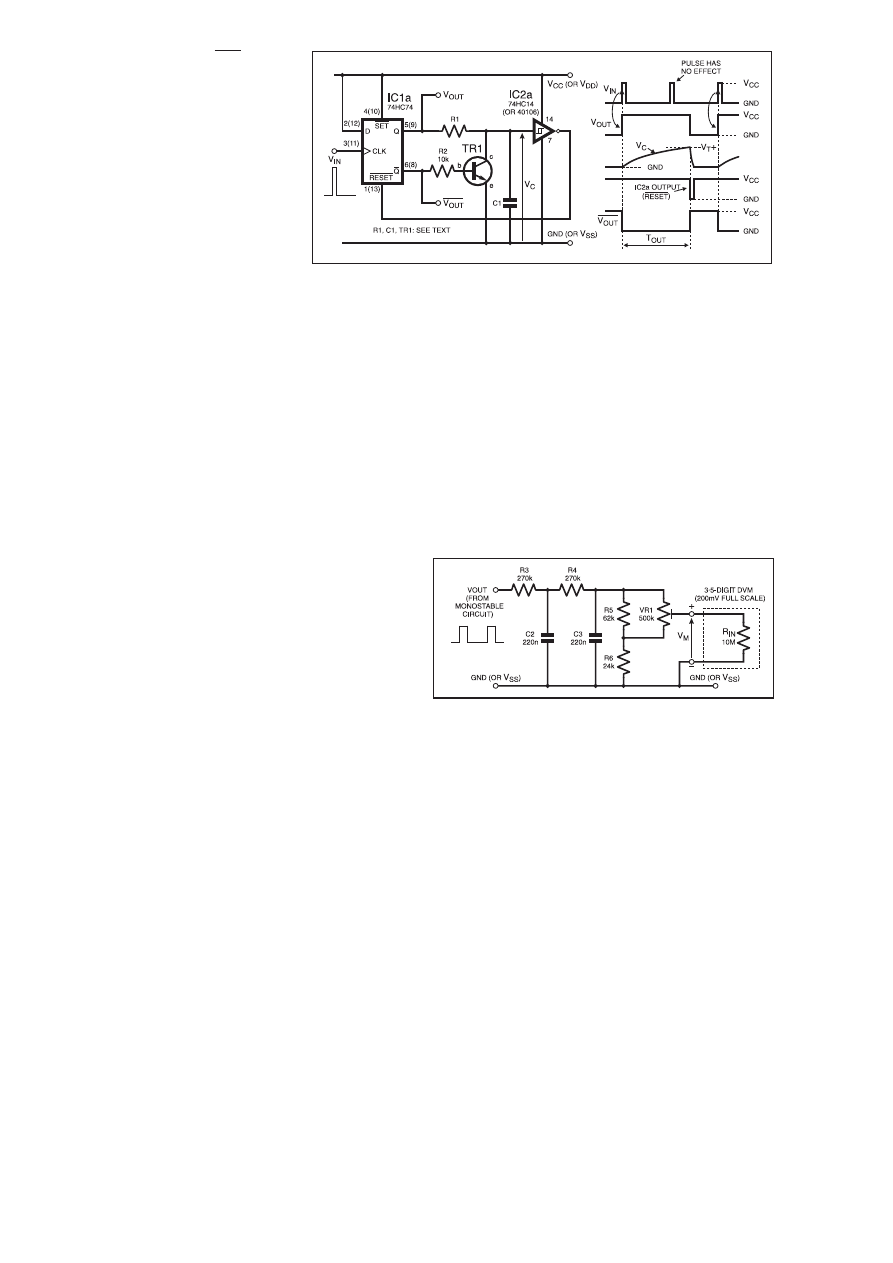
At the end of T
OUT
, when V
OUT
goes high,
TR1 turns on and rapidly discharges C1. The
capacitor voltage, V
C
, quickly falls below
IC2a’s negative-going threshold, V
T–
, at
which point IC2a’s output goes high, bringing
the flip-flop out of its reset state.
The device used for TR1 is not critical; any
small-signal npn transistor with adequate cur-
rent gain should suffice.
NON-RETRIGGERABLE
Since IC2a’s output is low only for a very
brief time, the circuit is ready to accept anoth-
er trigger pulse almost as soon as T
OUT
has
ended. Note that any trigger pulses that arrive
while V
OUT
is high have no effect on the cir-
cuit, which cannot be retriggered until T
OUT
has ended. This is illustrated by the second of
the V
IN
pulses which cannot clock the flip-
flop because V
OUT
is already high.
The actual value of T
OUT
will be influenced by tolerances in C1
and R1, and also by variations in supply voltage and V
T+
.
Nevertheless, provided resistor R1 is not too large (< 1M
9), the
actual value of T
OUT
agrees closely with the value predicted by the
expression above.
For example, a test circuit was built using a 74HC14 inverter for
IC2a, and the supply voltage, V
CC
, was set to 5·0V, resulting in a
value of 2·74V for V
T+
. Nominal values of 100k
9 and 10nF were
chosen for R1 and C1, although the measured values were 99·9k
9
and 10·08nF, such that T
OUT
predicted by the equation above is
800µs. The actual, measured value was found to be 806µs.
The circuit of Fig.6.13 is extremely good at ‘‘stretching’’ narrow
pulses. With R1 and C1 increased to 1M
9 and 10·68µF, a trigger
pulse just 100ns wide resulted in an output pulse of 8·9 seconds,
some 89 million times greater than the input pulse width!
Although T
OUT
could be finely tuned by using a variable resistor
(potentiometer) for R1, the circuit is not intended for precision tim-
ing applications, where a device like the 74HC221 would be a bet-
ter choice. Nevertheless, where a design happens to have an unused
flip-flop and Schmitt inverter available ‘‘for free’’, the circuit pro-
vides a simple and cost-effective way of implementing the ‘‘one-
shot’’ function.
FREQUENCY METER
With the addition of a few resistors and capacitors, the mono-
stable circuit of Fig.6.13 can be converted to a simple Frequency
Meter which displays the reading on a 3½-digit, 200mV DVM
(digital volt meter) module. The ‘‘add-on’’ circuit is shown in
Fig.6.14, where V
OUT
is the Q output of flip-flop IC1a in Fig.6.13.
The circuit is effectively a frequency-to-voltage converter, and
works on the principle that the average value of a series of constant
width, constant amplitude pulses is directly proportional to their fre-
quency. Therefore, by averaging the voltage of the pulses, the result
displayed on a DVM provides a direct indication of frequency.
The averaging function is provided by C2/R3 and C3/R4 which
together form a simple, two-pole, low-pass filter. For the circuit to
work properly, it is essential that the input pulses are of constant
width: this is why the filter circuit must be preceded by a non-retrig-
gerable monostable. Resistors R5 and R6, and trimmer preset VR1,
allow the output voltage, V
M
, to be adjusted to compensate for
tolerances in the monostable circuit.
The circuit is intended to display a full-scale frequency of 2kHz
on the DVM, that is, a reading of 199·9mV corresponds to a fre-
quency of 1·999kHz. Therefore, it is important that the mono-
stable’s pulse width, T
OUT
, must not exceed 500µs (the period of
2kHz), or the meter will go overrange. It doesn’t matter if T
OUT
is
somewhat less than 500µs, as this can be accommodated by
trimming VR1.
COMPONENT VALUES
For the monostable timing components, values of 3·3nF ±5% and
120k
9 ±1% should be used for C1 and R1 respectively. A single
inverter from the 74HC14 Hex Schmitt trigger inverter i.c. should
be used for IC2a, and the 5V (V
CC
) supply voltage should be regu-
lated to within ±4% (this can easily be achieved using a 78L05
regulator).
The resistors used in the filter circuit (Fig.6.14) should all be
±1% types, and VR1 should be a multiturn preset potentiometer
with a maximum tolerance of ±10%. The tolerance of capacitors C2
and C3 is not critical: ±10% parts are adequate. The DVM must
have a full-scale range of 200mV, and its input impedance must be
at least 10M
9 (a lower impedance would ‘‘load’’ the filter network
and could affect the results).
To calibrate the circuit, flip-flop IC1a should be clocked at a fre-
quency near full-scale (say, 1,950Hz), and preset VR1 should be
adjusted to produce a corresponding reading on the DVM (in this
example, it would be 195·0mV). The meter will then provide a
direct indication of frequency with a reading error of around ±1%
maximum.
Note that by preceding the monostable circuit with a series of
decade frequency dividers (such as the 74HC190 or 74HC390), the
circuit can be adapted to display any frequency in decade ranges up
to about 20MHz. Furthermore, if the input signal is fed to the
Schmitt trigger interface circuit described in Fig.5.3 of last month’s
article, the frequency meter is capable of responding to a variety of
different waveshapes.
BOUNCING CONTACTS
Perhaps one of the Schmitt’s most ubiquitous applications is that
of contact ‘‘bounce’’ suppression. Switch and relay contacts have
inherent elasticity; when they close, the kinetic energy in the mov-
ing parts causes the contacts to bounce back and forth many times
before finally settling down. The result is a series of contact inter-
ruptions, each of which will generate a narrow pulse when used in
an electronic circuit.
In certain applications, contact bounce is not a problem, but in
others, such as circuits featuring counters and shift registers, the
phenomenon can wreak havoc on the circuit’s behaviour. The dura-
tion of the bounce period (the time during which the contacts are
unstable), and the number of pulses generated will depend on the
type and quality of contacts used. Bounce periods of several hun-
dred microseconds are common, although this may be as long as
20ms for some contacts.
Incidentally, contact bounce also occurs when contacts open,
although this is usually less severe than when they close, and is
often a result of changes in contact resistance that occur when the
contacts separate.
Many techniques exist for eliminating the effects of contact
bounce. In microcontroller or microprocessor circuits, software
routines can be employed to ‘‘filter out’’ the glitches produced when
the contacts close.
In hardware, monostables, latches, flip-flops and specialised
‘‘debouncing’’ i.c.s can be used to provide immunity to contact
Everyday Practical Electronics, April 2001
299
Fig.6.13. Circuit diagram and its waveforms for a non-retriggerable monostable
constructed from “unused’’ parts.
Fig.6.14. An add-on filter circuit for frequency-to-voltage
conversion.
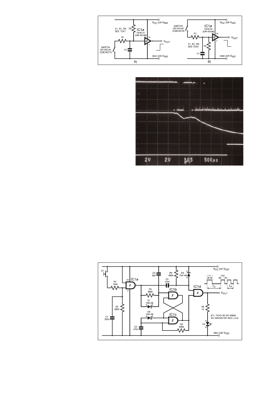
bounce. However, in terms of simplicity, the
Schmitt trigger debouncers shown in Fig.6.15
are often hard to beat.
PULSE FILTER
The circuit in Fig.6.15a provides a low-to-
high level change in output, V
OUT
, when the
contacts close, whereas that in Fig.6.15b gen-
erates a high-to-low level change. Both cir-
cuits rely on the low-pass filtering action pro-
vided by capacitor C1 and resistor R1.
In Fig.6.15a, R2 is a pull-up resistor which
ensures V
OUT
is low while the contacts are
open. When the contacts close, the junction of
R1/R2 is pulled down below the Schmitt’s
negative-going threshold, and capacitor C1 filters out the bounce
pulses which would otherwise appear, such that the signal at the
Schmitt input makes a ‘‘smooth’’ transition from V
CC
(or V
DD
) to a
low level. Therefore, V
OUT
makes just one, ‘‘clean’’, low-to-high
transition when the contacts are closed.
In Fig.6.15b, C1, R1 and R2 provide exactly the same function,
except that R2 behaves as a pull-down resistor such that V
OUT
is
held high while the contacts are open. In both cases, the time con-
stant formed by C1 × R1 should be made large enough to filter out
the worst-case number of bounce pulses likely to occur. In other
words, the time constant must be longer than the maximum antici-
pated bounce period.
Also, the ratio of R1 to R2 must be chosen carefully such that the
inverter’s input voltage can be pulled below the minimum negative-
going threshold (Fig.6.15a) or above the maximum positive-going
threshold (Fig.6.15b) when the contacts close. For a 74HC14 invert-
er working on a 5V rail, values in the region of 100k
W for R1 and
680k
W for R2 are usually suitable.
WAVEFORMS
The oscillograph in Fig.6.16 shows the waveforms observed for the
debouncer circuit of Fig.6.15a, using values of 100k
W and 680kW for
R1 and R2, and 10nF for C1. The top trace illustrates the contact
bounce: in this example, the bounce period lasts for about 1·5ms, dur-
ing which the contacts open and close more than twenty times.
The middle trace shows the filtered signal at the inverter’s input.
In this example, the C1/R1 time constant of 1ms is more than ade-
quate to filter out the bounce pulses, but for more severe cases, C1
could be increased to around 100nF.
The bottom trace shows how V
OUT
goes high about 2·5ms after
the contacts first start to close. In most cases, this delay will be of
no consequence, but in certain circuits (e.g.: where contacts are
used in timing applications) it may be necessary to take it into
account, particularly if a very large value has been chosen for C1 to
eliminate excessive bounce.
SINGLE OR MULTIPLE PULSER
We conclude our look at the ‘‘digital’’ Schmitt trigger by com-
bining some of the elementary circuits introduced in this article and
the previous one to create a more complex function.
The circuit diagram Fig.6.17 shows an Auto-Repeating Pushbut-
ton Pulser. A single press of the pushbutton switch, S1, generates a
single, positive-going pulse of width T1 at the
output. However, if switch S1 is held closed
long enough, the circuit ‘‘auto-repeats’’, that
is, it generates a continuous train of pulses of
width T2 until the pushbutton is released.
Components C1, R1, R2 and IC1a form the
debouncer: operation is exactly the same as the
debouncer in Fig.6.15b, but with the Schmitt
NAND replacing the inverter. Therefore, when
switch S1 is closed, a high-to-low transition is
produced at the output of IC1a. This low-going
pulse is differentiated by C4 and R4, producing
a negative-going ‘‘spike’’ at the input to IC1d.
Since IC1d’s other input is high at this point, the
NAND function results in a positive-going
pulse at V
OUT
. The width of this pulse, T1, is
determined by the C4/R4 time constant; this
part of the circuit should be familiar as the ‘‘dig-
ital differentiator’’ shown in Fig.5.9 in last
month’s article.
While switch S1 is closed and IC1a’s out-
put is low, capacitor C3 charges via R3, and
the voltage at their junction gradually falls. If S1 is opened, IC1a’s
output goes high and C3 is rapidly discharged via diode D1.
However, if S1 remains pressed long enough, C3 will charge suffi-
ciently for the voltage at IC1b’s input to fall below its negative-
going threshold voltage.
OPENING THE GATE
When this happens, the astable oscillator formed by IC1b, IC1c,
C2 and R5 is ‘‘gated’’ on and starts to run (this part of the circuit is
the same as the gated astable shown previously in Fig.6.5). The time
taken for capacitor C3 to charge sufficiently to ‘‘enable’’ the oscil-
lator constitutes the delay denoted T
D
, and depends on the C3/R3
time constant.
During this time, capacitor C4 has become fully charged (the
C4/R4 time constant is much smaller than the C3/R3 time constant),
Fig.6.15. Two circuit arrangements for Schmitt-based debouncers.
Fig.6.16. Waveforms for contact debouncer shown in
Fig.6.15a. Top trace: Switch contact bounce (2V/div.). Middle
trace: Filtered signal at Schmitt trigger input (2V/div.). Bottom
trace: Schmitt trigger output, V
OUT
(5V/div.). Timebase:
500
ms/div.
Fig.6.17. Circuit diagram for an auto-repeating pushbutton pulser.
300
Everyday Practical Electronics, April 2001

and so the voltage at the junction of C4/R4 is high. This allows the
astable pulses output by IC1c to propagate through IC1d, and
appear inverted at V
OUT
.
The width of the auto-repeating pulses, T2, and the period of
oscillation, T
P
, depend on the values selected for C2 and R5. Diode
D2 is not essential, but without it the width of the first astable pulse
(T2) will be slightly longer than the pulses that follow.
Notice that the pulser requires only one integrated circuit, either the
74HC132 or the 4093B. The circuit was tested using a 74HC132, with
a supply voltage, V
CC
, of 5·0V. Using the capacitor and resistor values
shown in Fig.6.17, the width of the first pulse, T1, was 238ms. The
delay, T
D
, from the switch being closed to the first of the auto-repeat-
ing pulses was 1·85s. Pulse width T2 was measured as 120ms, and the
pulses repeated at a rate of 4·7Hz (i.e., T
P
= 212ms). Note that these
are all typical values, and will vary with component tolerance and
changes in Schmitt threshold voltages.
Normally, the pulses at V
OUT
would be fed to a digital circuit like
a counter or shift register. However, light emitting diode D4 can be
used to provide visual indication of the pulses; series resistor R6
should be selected for optimum brightness. This kind of auto-
repeating function is often found in products like electronic clocks,
where a single press of the pushbutton increments or decrements a
variable just once, and a continuous press rapidly increases or
decreases the variable.
SPECIALITY SCHMITT DEVICES
Throughout this series, we’ve seen how the Schmitt trigger can
be used not just as an interface circuit, but also as the central ele-
ment in a variety of other functions. In view of its versatility, and
the fact that hysteresis is indispensable in many applications, the
Schmitt has been integrated into many “specialised” devices.
Next month, in the final part of this series, we’ll see how the
Schmitt trigger’s unique characteristics are used in a wide range of
devices, from optocouplers to voltage monitors.
Everyday Practical Electronics, April 2001
301
Annual subscription rates (2001):
6 MONTHS: UK £14.50, Overseas £17.50 (standard air
service), £27 (express airmail)
1 YEAR: UK £27.50, Overseas £33.50 (standard air service)
£51 (express airmail)
2 YEARS: UK £50.00, Overseas £62.00 (standard air service)
£97 (express airmail)
To: Everyday Practical Electronics,
Allen House, East Borough, Wimborne, Dorset BH21 1PF
Tel: 01202 881749 Fax: 01202 841692
E-mail: subs@epemag.wimborne.co.uk
Order online: www.epemag.wimborne.co.uk
MAKE SURE OF YOUR COPY –
ORDER A SUBSCRIPTION NOW
Name . . . . . . . . . . . . . . . . . . . . . . . . . . . . . . . . . . . . . . . . . . . . . . . . . . . . . . . . . . . . . . . . . . . . . . . . . . . . . . . . . . . . . . . . . . . . . . . . . .
Address . . . . . . . . . . . . . . . . . . . . . . . . . . . . . . . . . . . . . . . . . . . . . . . . . . . . . . . . . . . . . . . . . . . . . . . . . . . . . . . . . . . . . . . . . . . . . . . .
. . . . . . . . . . . . . . . . . . . . . . . . . . . . . . . . . . . . . . . . . . . . . . . . . . . . . . . . . . . . . . . . . . . . . . . . . . . . . . . . . . . . . . . . . . . . . . . . . . . . . . .
Post code . . . . . . . . . . . . . . . . . . . . . . . . . . . . . . . . . . . . . . . . . . . .Tel. . . . . . . . . . . . . . . . . . . . . . . . . . . . . . . . . . . . . . . . . . . . . .
I enclose payment of £..................... (cheque/PO in
£ sterling only),
payable to Everyday Practical Electronics
My card number is:
. . . . . . . . . . . . . . . . . . . . . . . . . . . . . . . . . . . . . . . . . . . . . . . . . . . . . . .
Signature.....................................................................................................
Card Ex. Date.......................................................Switch Issue No. ...........
Subscriptions can only start with the next available issue.
For back numbers see the
Back Issues
page.
04/01
SUBSCRIPTION ORDER FORM
Please print clearly, and check that you have the number correct
NEXT MONTH WE PUT YOU
IN THE PICTURE!
> PIC GRAPHICS L.C.D.
SCOPE
PLUS
> CAMCORDER MIXER
> D.C. MOTOR CONTROLLER
SAVE UP TO 66p AN ISSUE!

range of applications programs, hardware add-ons, etc.
The main difficulty for the uninitiated is deciding on the
specification that will best suit his or her needs. PCs
range from simple systems of limited capabilities up to
complex systems that can happily run applications that
would have been considered beyond the abilities of a
microcomputer not so long ago. It would be very easy to
choose a PC system that is inadequate to run your
applications efficiently, or one which goes beyond your
needs and consequently represents poor value for
money.
This book explains PC specifications in detail, and
the subjects covered include the following: Differences
between types of PC (XT, AT, 80386, etc); Maths co-
processors; Input devices (keyboards, mice, and digitis-
ers); Memory, including both expanded (EMS) and
extended RAM; RAM disks and disk caches; Floppy
disk drive formats and compatibility; Hard disk drives
(including interleave factors and access times); Display
adaptors, including all standard PC types (CGA,
Hercules, Super VGA, etc); Contains everything you
need to know if you can’t tell your EMS from your EGA!
INTRODUCING ROBOTICS WITH LEGO MINDSTORMS
Robert Penfold
Shows the reader how to build a variety of increasingly sophis-
ticated computer controlled robots using the brilliant Lego
Mindstorms Robotic Invention System (RIS). Initially covers
fundamental building techniques and mechanics needed to
construct strong and efficient robots using the various “click-
together’’ components supplied in the basic RIS kit. Then
explains in simple terms how the “brain’’ of the robot may be
programmed on screen using a PC and “zapped’’ to the robot
over an infra-red link. Also, shows how a more sophisticated
Windows programming language such as Visual BASIC may
be used to control the robots.
Details building and programming instructions provided,
including numerous step-by-step photographs.
ANDROIDS, ROBOTS AND ANIMATRONS
John Lovine
Build your own working robot or android using both off-
the-shelf and workshop constructed materials and
devices. Computer control gives these robots and
androids two types of artificial intelligence (an expert sys-
tem and a neural network). A lifelike android hand can be
built and programmed to function doing repetitive tasks. A
fully animated robot or android can also be built and pro-
grammed to perform a wide variety of functions.
The contents include an Overview of State-of-the-Art
Robots; Robotic Locomotion; Motors and Power
Controllers; All Types of Sensors; Tilt; Bump; Road and
Wall Detection; Light; Speech and Sound Recognition;
Robotic Intelligence (Expert Type) Using a Single-Board
Computer Programmed in BASIC; Robotic Intelligence
(Neutral Type) Using Simple Neural Networks (Insect
Intelligence); Making a Lifelike Android Hand; A
Computer-Controlled Robotic Insect Programmed in
BASIC; Telepresence Robots With Actual Arcade and
Virtual Reality Applications; A Computer-Controlled
Robotic Arm; Animated Robots and Androids; Real-World
Robotic Applications.
BASIC RADIO PRINCIPLES AND TECHNOLOGY
Ian Poole
Radio technology is becoming increasingly important in
today’s high technology society. There are the traditional
uses of radio which include broadcasting and point to
point radio as well as the new technologies of satellites
and cellular phones. All of these developments mean
there is a growing need for radio engineers at all levels.
Assuming a basic knowledge of electronics, this book
provides an easy to understand grounding in the topic.
Chapters in the book: Radio Today, Yesterday, and
Tomorrow; Radio Waves and Propagation; Capacitors,
Inductors, and Filters;
Modulation;
Receivers;
Transmitters; Antenna Systems; Broadcasting; Satellites;
Personal Communications;
Appendix – Basic
Calculations.
PROJECTS FOR RADIO AMATEURS AND S.W.L.S.
R. A. Penfold
This book describes a number of electronic circuits, most
of which are quite simple, which can be used to enhance
the performance of most short wave radio systems.
The circuits covered include: An aerial tuning unit; A
simple active aerial; An add-on b.f.o. for portable sets;
A wavetrap to combat signals on spurious responses; An
audio notch filter; A parametric equaliser; C.W. and S.S.B.
audio filters; Simple noise limiters; A speech processor; A
volume expander.
Other useful circuits include a crystal oscillator, and
RTTY/C.W. tone decoder, and a RTTY serial to parallel
converter. A full range of interesting and useful circuits for
short wave enthusiasts.
Everyday Practical Electronics Books
263 pages
£15.99
Order code NE30
TEACH-IN No. 7
ANALOGUE AND DIGITAL ELECTRONICS COURSE
(published by
Everyday Practical Electronics)
Alan Winstanley and Keith Dye B.Eng(Tech)AMIEE
This highly acclaimed
EPE Teach-In series, which
included the construction and use of the Mini Lab and
Micro Lab test and development units, has been put
together in book form.
An interesting and thorough tutorial series aimed
specifically at the novice or complete beginner in
electronics. The series is designed to support those
undertaking either GCSE Electronics or GCE
Advanced Levels, and starts with fundamental
principles.
If you are taking electronics or technology at school
or college, this book is for you. If you just want to learn
the basics of electronics or technology you must make
sure you see it.
Teach-In No. 7 will be invaluable if you
are considering a career in electronics or even if you
are already training in one. The Mini Lab and software
enable the construction and testing of both demonstra-
tion and development circuits. These learning aids
bring electronics to life in an enjoyable and interesting
way: you will both see and hear the electron in action!
The Micro Lab microprocessor add-on system will
appeal to higher level students and those developing
microprocessor projects.
TEACH-IN 2000 plus FREE software
John Becker
The
Teach-In 2000 series is now available on CD-
ROM, see advert elsewhere in this issue.
AN INTRODUCTION TO AMATEUR RADIO
I. D. Poole
Amateur radio is a unique and fascinating hobby which
has attracted thousands of people since it began at the
turn of the century. This book gives the newcomer a com-
prehensive and easy to understand guide through the
subject so that the reader can gain the most from the
hobby. It then remains an essential reference volume to
be used time and again. Topics covered include the basic
aspects of the hobby, such as operating procedures, jar-
gon and setting up a station. Technical topics covered
include propagation, receivers, transmitters and aerials
etc.
SIMPLE SHORT WAVE RECEIVER CONSTRUCTION
R. A. Penfold
Short wave radio is a fascinating hobby, but one that
seems to be regarded by many as an expensive pastime
these days. In fact it is possible to pursue this hobby for a
minimal monetary outlay if you are prepared to undertake
a bit of d.i.y., and the receivers described in this book can
all be built at low cost. All the sets are easy to costruct, full
wiring diagrams etc. are provided, and they are suitable
for complete beginners. The receivers only require simple
aerials, and do not need any complex alignment or other
difficult setting up procedures.
The topics covered in this book include: The broadcast
bands and their characteristics; The amateur bands and
their characteristics; The propagation of radio signals;
Simple aerials; Making an earth connection; Short wave
crystal set; Simple t.r.f. receivers; Single sideband recep-
tion; Direct conversion receiver.Contains everything you
need to know in order to get started in this absorbing
hobby.
88 pages
£4.45
Order code BP275
152 pages
£4.95
Order code TI7
92 pages
£4.45
Order code BP304
Radio
DIRECT
BOOK
SERVICE
N
NO
OT
TE
E:: A
AL
LL
L P
PR
RIIC
CE
ES
S
IIN
NC
CL
LU
UD
DE
E U
UK
K P
PO
OS
ST
TA
AG
GE
E
The books listed have been
selected by
Everyday
Practical Electronics
editorial
staff as being of special inter-
est to everyone involved in
electronics and computing.
They are supplied by mail
order to your door. Full order-
ing details are given on the
last book page.
For a further selection
of books see the next
two issues of
EPE
.
Robotics
Computers and Computing
MULTIMEDIA ON THE PC
Ian R. Sinclair
In this book, you’ll find out what a CD ROM is, how it
works, and why it is such a perfect add-on for a PC,
allowing you to buy programmes, text, graphics and
sound on a CD. It also describes the installation of a CD
ROM drive and a sound card, pointing out the common
problems that arise, and then shows how to use them to
create a complete multimedia presentation that con-
tains text, photos, a soundtrack with your own voice
recorded as a commentary, even animation and edited
video footage.
HOW TO BUILD YOUR OWN PC
Morris Rosenthal
More and more people are building the own PCs. They
get more value for their money, they create exactly the
machine they want, and the work is highly satisfying
and actually fun. That is, if they have a unique begin-
ner’s guide like this one, which visually demonstrates
how to construct a state-of-the-art computer from start
to finish.
Through 150 crisp photographs and clear but minimal
text, readers will confidently absorb the concepts of
computer building. The extra-big format makes it easy
to see what’s going on in the pictures. For non-special-
ists, there’s even a graphical glossary that clearly
illustrates technical terms. The author goes “under the
hood’’ and shows step-by-step how to create a socket 7
(Pentium and non-intel chipsets) and a Slot 1 (Pentium
II) computer, covering: What first-time builders need to
know; How to select and purchase parts; How to
assemble the PC; How to install Windows 98. The few
existing books on this subject, although badly outdated,
are in steady demand. This one delivers the expertise
and new technology that fledgling computer builders
are eagerly looking for.
UNDERSTANDING PC SPECIFICATIONS
R. A. Penfold (Revised Edition)
If you require a microcomputer for business applica-
tions, or a high quality home computer, an IBM PC or
compatible is often the obvious choice. They are com-
petitively priced, and are backed up by an enormous
150 pages
£5.49
Order code BP257
184 pages
£12.95
Order code PC112
224 pages – large format
£21.99
Order code MGH2
128 pages
£5.45
Order code BP282
302
Everyday Practical Electronics, April 2001
224 pages
£22.99
Order code MGH1
288 pages – large format
£14.99
Order code BP901
C
CD
D--R
RO
OM
M

AN INTRODUCTION TO LOUDSPEAKERS
AND ENCLOSURE DESIGN
V. Capel
This book explores the various features, good points and
snags of speaker designs. It examines the whys and
wherefores so that the reader can understand the princi-
ples involved and so make an informed choice of design,
or even design loudspeaker enclosures for him – or herself.
Crossover units are also explained, the various types, how
they work, the distortions they produce and how to avoid
them. Finally there is a step-by-step description of the con-
struction of the
Kapellmeister loudspeaker enclosure.
ELECTRONIC MUSIC AND MIDI PROJECTS
R. A. Penfold
Whether you wish to save money, boldly go where no musi-
cian has gone before, rekindle the pioneering spirit, or sim-
ply have fun building some electronic music gadgets, the
designs featured in this book should suit your needs. The
projects are all easy to build, and some are so simple that
even complete beginners at electronic project construction
can tackle them with ease. Stripboard layouts are provided
for every project, together with a wiring diagram. The
mechanical side of construction has largely been left to
individual constructors to sort out, simply because the vast
majority of project builders prefer to do their own thing in
this respect.
None of the designs requires the use of any test equip-
ment in order to get them set up properly. Where any set-
ting up is required, the procedures are very straightforward,
and they are described in detail.
Projects covered: Simple MIIDI tester, Message grabber,
Byte grabber, THRU box, MIDI auto switcher, Auto/manual
switcher, Manual switcher, MIDI patchbay, MIDI controlled
switcher, MIDI lead tester, Program change pedal,
Improved program change pedal, Basic mixer, Stereo
mixer, Electronic swell pedal, Metronome, Analogue echo
unit.
VIDEO PROJECTS FOR THE ELECTRONICS
CONSTRUCTOR
R. A. Penfold
Written by highly respected author R. A. Penfold, this book
contains a collection of electronic projects specially designed
for video enthusiasts. All the projects can be simply con-
structed, and most are suitable for the newcomer to project
construction, as they are assembled on stripboard.
There are faders, wipers and effects units which will add
sparkle and originality to your video recordings, an audio
mixer and noise reducer to enhance your soundtracks and a
basic computer control interface. Also, there’s a useful selec-
tion on basic video production techniques to get you started.
Complete with explanations of how the circuit works, shop-
ping lists of components, advice on construction, and guid-
ance on setting up and using the projects, this invaluable
book will save you a small fortune.
Circuits include: video enhancer, improved video
enhancer, video fader, horizontal wiper, improved video
wiper, negative video unit, fade to grey unit, black and white
keyer, vertical wiper, audio mixer, stereo headphone
amplifier, dynamic noise reducer, automatic fader, pushbut-
ton fader, computer control interface, 12 volt mains power
supply.
COMPUTERS AND MUSIC – AN INTRODUCTION
R. A. Penfold
Computers are playing an increasingly important part in the
world of music, and the days when computerised music was
strictly for the fanatical few are long gone.
If you are more used to the black and white keys of a synth
keyboard than the QWERTY keyboard of a computer, you
may be understandably confused by the jargon and termi-
nology bandied about by computer buffs. But fear not, setting
up and using a computer-based music making system is not
as difficult as you might think.
This book will help you learn the basics of computing,
running applications programs, wiring up a MIDI system and
using the system to good effect, in fact just about everything
you need to know about hardware and the programs, with no
previous knowledge of computing needed or assumed. This
Bebop To The Boolean Boogie
By Clive (call me Max)
Maxfield
Specially imported by
EPE –
Excellent value
An Unconventional Guide to
Electronics Fundamentals,
Components and Processe
s
This book gives the “big picture’’ of
digital electronics. This indepth, highly
readable, up-to-the-minute guide
shows you how electronic devices
work and how they’re made. You’ll dis-
cover how transistors operate, how
printed circuit boards are fabricated,
and what the innards of memory ICs
look like. You’ll also gain a working knowledge of Boolean Algebra
and Karnaugh Maps, and understand what Reed-Muller logic is and
how it’s used. And there’s much, MUCH more (including a recipe for
a truly great seafood gumbo!). Hundreds of carefully drawn illustra-
tions clearly show the important points of each topic. The author’s
tongue-in-cheek British humor makes it a delight to read, but this is a
REAL technical book, extremely detailed and accurate. A great refer-
ence for your own shelf, and also an ideal gift for a friend or family
member who wants to understand what it is you do all day. . . .
Bebop Bytes
Back
By Clive “Max’’ Maxfield
and Alvin Brown
Specially imported by
EPE –
Excellent value
An Unconventional Guide
To Computers
Plus FREE CD-ROM which includes:
Fully Functional Internet-Ready
Virtual Computer with Interactive Labs
This follow-on to
Bebop to the
Boolean Boogie is a multimedia
extravaganza of information about
how computers work. It picks up
where “Bebop I’’ left off, guiding you
through the fascinating world of computer design. . . and you’ll have
a few chuckles, if not belly laughs, along the way. In addition to over
200 megabytes of mega-cool multimedia, the accompanying CD-
ROM (for Windows 95 machines only) contains a virtual microcom-
puter, simulating the motherboard and standard computer peripher-
als in an extremely realistic manner. In addition to a wealth of tech-
nical information, myriad nuggets of trivia, and hundreds of careful-
ly drawn illustrations, the book contains a set of lab experiments for
the virtual microcomputer that let you recreate the experiences of
early computer pioneers.
Theory and Reference
470 pages – large format
£26.95
Order code BEB1
Over 500 pages – large format
£31.95
Order code BEB2
DIGITAL GATES AND FLIP-FLOPS
Ian R. SInclair
This book, intended for enthusiasts, students and technicians,
seeks to establish a firm foundation in digital electronics by treating
the topics of gates and flip-flops thoroughly and from the beginning.
Topics such as Boolean algebra and Karnaugh mapping are
explained, demonstrated and used extensively, and more attention
is paid to the subject of synchronous counters than to the simple but
less important ripple counters.
No background other than a basic knowledge of electronics is
assumed, and the more theoretical topics are explained from the
beginning, as also are many working practices. The book concludes
with an explanation of microprocessor techniques as applied to
digital logic.
200 pages
£9.95
Order code PC106
DIGITAL ELECTRONICS – A PRACTICAL APPROACH
With FREE Software: Number One Systems – EASY-PC
Professional XM and Pulsar (Limited Functionality)
Richard Monk
Covers binary arithmetic, Boolean algebra and logic gates, combination
logic, sequential logic including the design and construction of asyn-
chronous and synchronous circuits and register circuits. Together with a
considerable practical content plus the additional attraction of its close
association with computer aided design including the FREE software.
There is a ‘blow-by-blow’ guide to the use of EASY-PC Professional
XM (a schematic drawing and printed circuit board design computer
package). The guide also conducts the reader through logic circuit sim-
ulation using Pulsar software. Chapters on p.c.b. physics and p.c.b.
production techniques make the book unique, and with its host of project
ideas make it an ideal companion for the integrative assignment and
common skills components required by BTEC and the key skills
demanded by GNVQ. The principal aim of the book is to provide a
straightforward approach to the understanding of digital electronics.
Those who prefer the ‘Teach-In’ approach or would rather experiment
with some simple circuits should find the book’s final chapters on print-
ed circuit board production and project ideas especially useful.
250 pages
£17.99
Order code NE28
Music, Audio and Video
book will help you to choose the right components for a sys-
tem to suit your personal needs, and equip you to exploit that
system fully.
THE INVENTOR OF STEREO – THE LIFE AND WORKS
OF ALAN DOWER BLUMLEIN
Robert Charles Alexander
This book is the definitive study of the life and works of one
of Britain’s most important inventors who, due to a cruel set
of circumstances, has all but been overlooked by history.
Alan Dower Blumlein led an extraordinary life in which his
inventive output rate easily surpassed that of Edison, but
whose early death during the darkest days of World War
Two led to a shroud of secrecy which has covered his life
and achievements ever since.
His 1931 Patent for a Binaural Recording System was so
revolutionary that most of his contemporaries regarded it as
more than 20 years ahead of its time. Even years after his
death, the full magnitude of its detail had not been fully uti-
lized. Among his 128 patents are the principal electronic cir-
cuits critical to the development of the world’s first elecron-
ic television system. During his short working life, Blumlein
produced patent after patent breaking entirely new ground
in electronic and audio engineering.
During the Second World War, Alan Blumlein was deeply
engaged in the very secret work of radar development and
contributed enormously to the system eventually to become
‘H25’ – blind-bombing radar. Tragically, during an experi-
mental H2S flight in June 1942, the Halifax bomber in which
Blumlein and several colleagues were flying, crashed and
all aboard were killed. He was just days short of his thirty-
ninth birthday.
HIGH POWER AUDIO AMPLIFIER CONSTRUCTION
R. A. Penfold
Practical construction details of how to build a number of
audio power amplifiers ranging from about 50 to 300/400
watts r.m.s. includes MOSFET and bipolar transistor
designs.
420 pages
£15.99
Order code NE32
138 pages
£10.95
Order code PC116
148 pages
Temporarily out of print
174 pages
Temporarily out of print
124 pages
£10.95
Order code PC115
96 pages
£4.49
Order code BP277
Everyday Practical Electronics, April 2001
303
FREE
SOFTWARE
FREE
CD-ROM

regulator circuits; negative supply generators and voltage
boosters; digital dividers; decoders, etc; counters and dis-
play drivers; D/A and A/D converters; opto-isolators,
flip/flops, noise generators, tone decoders, etc.
Over 170 circuits are provided, which it is hoped will be
useful to all those involved in circuit design and applica-
tion, be they professionals, students or hobbyists.
PRACTICAL ELECTRONIC FILTERS
Owen Bishop
This book deals with the subject in a non-mathematical
way. It reviews the main types of filter, explaining in sim-
ple terms how each type works and how it is used.
The book also presents a dozen filter-based projects
with applications in and around the home or in the
constructor’s workshop. These include a number of audio
projects such as a rythm sequencer and a multi-voiced
electronic organ.
Concluding the book is a practical step-by-step guide to
designing simple filters for a wide range of purposes, with
circuit diagrams and worked examples.
ELECTRONIC HOBBYISTS DATA BOOK
R. A. Penfold
This book should tell you everything you are ever likely to
want to know about hobby electronics, but did not know
where to ask or refer. Comprehensive contents pages
makes it easy to quickly locate the data you require.
The subjects covered include: Common circuits, and
related data (including helpful graphs and tables of val-
ues); Colour codes for resistors, capacitors and inductors;
Pinout details for a wide range of CMOS and TTL devices,
plus basic data on the various logic families; Pinout
details and basic data for a wide range of operational
amplifiers; Data and leadout information for a wide range
of transistors, FETs, power FETs, triacs, thyristors,
diodes, etc; General data including MIDI message coding,
radio data, ASCII/Baudot coding, decibel ratios, etc.
50 SIMPLE LED CIRCUITS
R. N. Soar
Contains 50 interesting and useful circuits and applica-
tions, covering many different branches of electronics,
using one of the most inexpensive and freely available
components – the light-emitting diode (LED). Also
includes circuits for the 707 common anode display.
BOOK 2 50 more l.e.d. circuits.
CIRCUIT SOURCE BOOK 1
A. Penfold
Written to help you create and experiment with your own
electronic designs by combining and using the various
standard “building block’’ circuits provided. Where applic-
able, advice on how to alter the circuit parameters is
given.
The circuits covered in this book are mainly concerned
with analogue signal processing and include: Audio
amplifiers (op.amp and bipolar transistors); audio power
amplifiers; d.c. amplifiers; highpass, lowpass, bandpass
and notch filters; tone controls; voltage controlled ampli-
fiers and filters; triggers and voltage comparators; gates
and electronic switching; bargraphs; mixers; phase
shifters, current mirrors, hold circuits, etc.
Over 150 circuits are provided, which it is hoped will be
useful to all those involved in circuit design and applica-
tion, be they professionals, students or hobbyists.
A BEGINNER’S GUIDE TO TTL DIGITAL ICs
R. A. Penfold
This book first covers the basics of simple logic circuits in
general, and then progresses to specific TTL logic
integrated circuits. The devices covered include gates,
oscillators, timers, flip/flops, dividers, and decoder cir-
cuits. Some practical circuits are used to illustrate the use
of TTL devices in the “real world’’.
HOW TO USE OP.AMPS
E. A. Parr
This book has been written as a designer’s guide
covering many operational amplifiers, serving both as a
source book of circuits and a reference book for design
calculations. The approach has been made as non-math-
ematical as possible.
CIRCUIT SOURCE BOOK 2
R. A. Penfold
This book will help you to create and experiment with your
own electronic designs by combining and using the vari-
ous standard “building blocks’’ circuits provided. Where
applicable, advice on how to alter the circuit parameters
is provided.
The circuits covered are mainly concerned with signal
generation, power supplies, and digital electronics.
The topics covered in this book include: 555 oscillators;
sinewave oscillators; function generators; CMOS oscilla-
tors; voltage controlled oscillators; radio frequency
oscillators; 555 monostables; CMOS monostables; TTL
monostables; precision long timers; power supply and
ELECTRONIC PROJECTS FOR EXPERIMENTERS
R. A. Penfold
Many electronic hobbyists who have been pursuing their
hobby for a number of years seem to suffer from the
dreaded “seen it all before’’ syndrome. This book is fairly
and squarely aimed at sufferers of this complaint, plus
any other electronics enthusiasts who yearn to try some-
thing a bit different. No doubt many of the projects fea-
tured here have practical applications, but they are all
worth a try for their interest value alone.
The subjects covered include:- Magnetic field detector,
Basic Hall effect compass, Hall effect audio isolator, Voice
scrambler/descrambler, Bat detector, Bat style echo loca-
tion, Noise cancelling, LED stroboscope, Infra-red “torch’’,
Electronic breeze detector, Class D power amplifier,
Strain gauge amplifier, Super hearing aid.
PRACTICAL FIBRE-OPTIC PROJECTS
R. A. Penfold
While fibre-optic cables may have potential advantages
over ordinary electric cables, for the electronics
enthusiast it is probably their novelty value that makes
them worthy of exploration. Fibre-optic cables provide an
innovative interesting alternative to electric cables, but in
most cases they also represent a practical approach to
the problem. This book provides a number of tried and
tested circuits for projects that utilize fibre-optic cables.
The projects include:- Simple audio links, F.M. audio
link, P.W.M. audio links, Simple d.c. links, P.W.M. d.c. link,
P.W.M. motor speed control, RS232C data links, MIDI
link, Loop alarms, R.P.M. meter.
All the components used in these designs are readily
available, none of them require the constructor to take out
a second mortgage.
ELECTRONIC PROJECT BUILDING FOR BEGINNERS
R. A. Penfold
This book is for complete beginners to electronic project
building. It provides a complete introduction to the practi-
cal side of this fascinating hobby, including the following
topics:
Component identification, and buying the right parts;
resistor colour codes, capacitor value markings, etc;
242 pages
£6.45
Order code BP396
138 pages
£5.45
Order code BP371
64 pages
Temporarily out of print
88 pages
£5.49
Order code BP299
192 pages
£5.45
Order code BP322
BOOK ORDERING DETAILS
All prices include UK postage. For postage to Europe (air) and the rest of the world (surface)
please add £1 per book. For the rest of the world airmail add £2 per book. Send a PO, cheque,
international money order (£ sterling only) made payable to Direct Book Service or card details,
Visa, Mastercard or Switch – minimum card order is £5 – to: DIRECT BOOK SERVICE, ALLEN
HOUSE, EAST BOROUGH, WIMBORNE, DORSET BH21 1PF.
Books are normally sent within seven days of receipt of order, but please allow 28 days for
delivery – more for overseas orders.
Please check price and availability (see latest issue of
Everyday Practical Electronics
) before ordering from old lists.
For a further selection of books see the next two issues of
EPE.
DIRECT BOOK SERVICE IS A DIVISION OF WIMBORNE PUBLISHING LTD.
Tel 01202 881749 Fax 01202 841692. E-mail: dbs@epemag.wimborne.co.uk
Order from our online shop at: www.epemag.wimborne.co.uk/shopdoor.htm
50 pages
£3.49
Order code BP87
182 pages
£5.49
Order code BP321
142 pages
£5.45
Order code BP332
160 pages
£4.49
Order code BP88
advice on buying the right tools for the job; soldering;
making easy work of the hard wiring; construction meth-
ods, including stripboard, custom printed circuit boards,
plain matrix boards, surface mount boards and wire-wrap-
ping; finishing off, and adding panel labels; getting “prob-
lem’’ projects to work, including simple methods of fault-
finding.
In fact everything you need to know in order to get start-
ed in this absorbing and creative hobby.
A BEGINNER’S GUIDE TO MODERN ELECTRONIC
COMPONENTS
R. A. Penfold
The purpose of this book is to provide practical infor-
mation to help the reader sort out the bewildering array
of components currently on offer. An advanced
knowledge of the theory of electronics is not needed,
and this book is not intended to be a course in elec-
tronic theory. The main aim is to explain the differences
between components of the same basic type (e.g. car-
bon, carbon film, metal film, and wire-wound resistors)
so that the right component for a given application can
be selected. A wide range of components are included,
with the emphasis firmly on those components that are
used a great deal in projects for the home constructor.
HOW TO USE OSCILLOSCOPES AND OTHER TEST
EQUIPMENT
R. A. Penfold
This book explains the basic function of an oscilloscope,
gives a detailed explanation of all the standard controls,
and provides advice on buying. A separate chapter
deals with using an oscilloscope for fault finding on
linear and logic circuits, plenty of example waveforms
help to illustrate the control functions and the effects of
various fault conditions. The function and use of various
other pieces of test equipment are also covered, includ-
ing signal generators, logic probes, logic pulsers, and
crystal calibrators.
Circuits, Data and Design
Project Building & Testing
132 pages
£5.45
Order code BP374
135 pages
£5.49
Order code BP392
166 pages
£5.49
Order code BP285
304
Everyday Practical Electronics, April 2001
BOOK ORDER FORM
Full name: ...............................................................................................................................................
Address: ..................................................................................................................................................
.................................................................................................................................................................
.................................................................................................................................................................
.............................................. Post code: ........................... Telephone No: .............................................
Signature: ................................................................................................................................................
I enclose cheque/PO payable to DIRECT BOOK SERVICE for £ ...................................................
Please charge my Visa/Mastercard/Switch £ ................................... Card expiry date....................
Card Number ........................................................................................... Switch Issue No.....................
Please send book order codes: ..............................................................................................................
.................................................................................................................................................................
Please continue on separate sheet of paper if necessary
104 pages
£4.00
Order code BP267
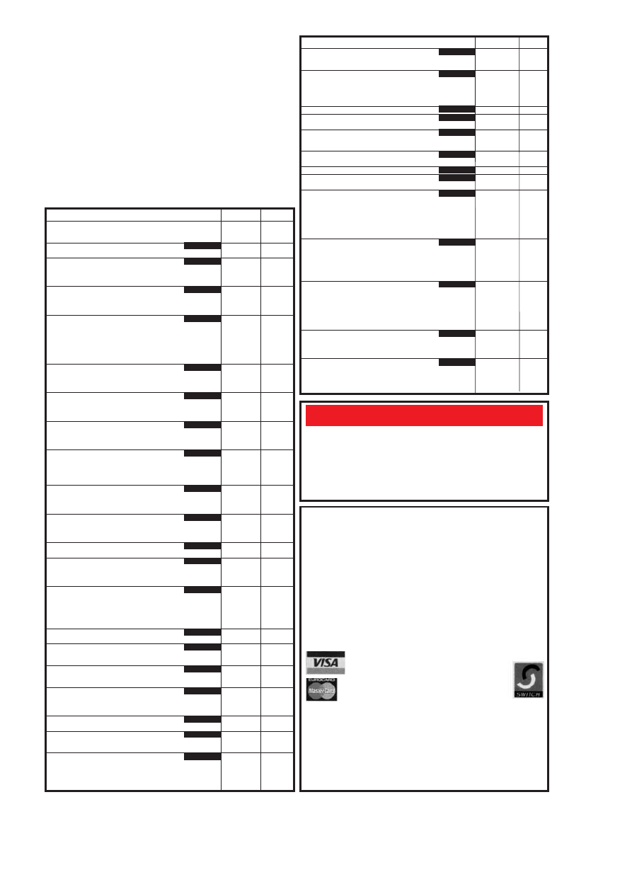
PROJECT TITLE
Order Code
Cost
oPIC16x84 Toolkit
JULY ’98
196
£6.96
oGreenhouse Computer
Control Board
197
£9.08
Float Charger
AUG ’98
199
£6.59
Lightbulb Saver
202
£3.00
Personal Stereo Amplifier
SEPT ’98
932
£3.00
(Multi-project PCB)
oGreenhouse Radio Link
200
£8.32
oPIC Altimeter
201
£8.15
Voice Processor
OCT ’98
203
£7.18
IR Remote Control
–Transmitter
205
£3.00
– Receiver
206
£3.50
oPIC Tape Measure
NOV ’98
207
£6.82
Electronic Thermostat – T-Stat
208
£4.00
PhizzyB
£14.95
A – PCB B – CD-ROM C – Prog. Microcontroller
Bee (A)(B)(C)
each
15-Way IR Remote Control
Switch Matrix
211
£3.00
15-Way Rec/Decoder
212
£4.00
Damp Stat
DEC ’98
209
£4.50
Handheld Function Generator
213
£4.00
oFading Christmas Lights
215
£5.16
PhizzyB I/O Board (4-section)
216
£3.95
Twinkle Twinkle Reaction Game
JAN ’99
210
£7.55
oEPE Mind PICkler
214
£6.30
PhizzyB I/O Board (4-section)
216
£3.95
Alternative Courtesy Light Controller
217
£6.72
Light Alarm
FEB ’99
218
£6.78
oWireless Monitoring System Transmitter
219+a
£9.92
Receiver
220+a
£8.56
oPIC MIDI Sustain Pedal Software only
–
–
oWireless Monitoring System-2
MAR ’99
See
F.M. Trans/Rec Adaptors
219a/220a
Feb ’99
oTime and Date Generator
221
£7.37
Auto Cupboard Light
222
£6.36
Smoke Absorber
223
£5.94
Ironing Board Saver
APR ’99
224
£5.15
Voice Record/Playback Module
225
£5.12
Mechanical Radio (pair)
226A&B
£7.40
oVersatile Event Counter
207
£6.82
PIC Toolkit Mk2
MAY ’99
227
£8.95
A.M./F.M. Radio Remote Control
Transmitter
228
£3.00
Receiver
229
£3.20
oMusical Sundial
JUNE ’99
231
£9.51
PC Audio Frequency Meter
232
£8.79
oEPE Mood PICker
JULY ’99
233
£6.78
12V Battery Tester
234
£6.72
Intruder Deterrent
235
£7.10
L.E.D. Stroboscope (Multi-project PCB)
932
£3.00
Ultrasonic Puncture Finder
AUG ’99
236
£5.00
o8-Channel Analogue Data Logger
237
£8.88
Buffer Amplifier (Oscillators Pt 2)
238
£6.96
Magnetic Field Detective
239
£6.77
Sound Activated Switch
240
£6.53
Freezer Alarm (Multi-project PCB)
932
£3.00
Child Guard
SEPT ’99
241
£7.51
Variable Dual Power Supply
242
£7.64
Micro Power Supply
OCT ’99
243
£3.50
oInterior Lamp Delay
244
£7.88
Mains Cable Locator (Multi-project PCB)
932
£3.00
Vibralarm
NOV ’99
230
£6.93
Demister One-Shot
245
£6.78
oGinormous Stopwatch – Part 1
246
£7.82
oGinormous Stopwatch – Part 2
DEC ’99
Giant Display
247
£7.85
Serial Port Converter
248
£3.96
Loft Guard
249
£4.44
Scratch Blanker
JAN ’00
250
£4.83
Flashing Snowman (Multi-project PCB)
932
£3.00
oVideo Cleaner
FEB ’00
251
£5.63
Find It
252
£4.20
oTeach-In 2000 – Part 4
253
£4.52
High Performance
MAR ’00
254, 255
£5.49
Regenerative Receiver
256
Set
oEPE Icebreaker – PCB257, programmed
PIC16F877 and floppy disc
Set only
£22.99
Parking Warning System
258
£5.08
Everyday Practical Electronics, April 2001
305
Printed circuit boards for most recent
EPE constructional projects are available from
the PCB Service, see list. These are fabricated in glass fibre, and are fully drilled and
roller tinned. All prices include VAT and postage and packing. Add £1 per board for
airmail outside of Europe. Remittances should be sent to The PCB Service,
Everyday Practical Electronics, Allen House, East Borough, Wimborne, Dorset
BH21 1PF. Tel: 01202 881749; Fax 01202 841692; E-mail: orders@epemag.wim-
borne.co.uk. On-line Shop: www.epemag.wimborne.co.uk/shopdoor.htm.
Cheques should be crossed and made payable to
Everyday Practical Electronics
(Payment in £ sterling only).
NOTE: While 95% of our boards are held in stock and are dispatched within
seven days of receipt of order, please allow a maximum of 28 days for delivery
– overseas readers allow extra if ordered by surface mail.
Back numbers or photostats of articles are available if required – see the
Back
Issues page for details.
Please check price and availability in the latest issue.
Boards can only be supplied on a payment with order basis.
Software programs for
EPE projects marked with an asterisk
(
are available on 3.5
inch PC-compatible disks or
free from our Internet site. The following disks are
available: PIC Tutorial (Mar-May ’98 issues); PIC Toolkit Mk2 (May-Jun ’99
issues);
EPE Disk 1 (Apr ’95-Dec ’98 issues); EPE Disk 2 (Jan-Dec ’99); EPE Disk
3 (Jan-Dec ’00).
EPE Disk 4 (Jan ’01 issue to current cover date); EPE Teach-In
2000;
EPE Interface Disk 1 (October ’00 issue to current cover date). The disks
are obtainable from the
EPE PCB Service at £3.00 each (UK) to cover our admin
costs (the software itself is
free). Overseas (each): £3.50 surface mail, £4.95 each
airmail. All files can be downloaded
free from our Internet FTP site:
ftp://ftp.epemag.wimborne.co.uk.
EPE PRINTED CIRCUIT
BOARD SERVICE
Order Code
Project
Quantity
Price
..............................................................................
Name ...................................................................
Address ...............................................................
..............................................................................
I enclose payment of £................ (cheque/PO in £ sterling only) to:
Everyday
Practical Electronics
MasterCard, Visa or Switch No.
Minimum order for cards £5
Switch Issue No. . . . .
Card No. . . . . . . . . . . . . . . . . . . . . . . . . . . . . . . . . . . . . . .
Signature....................................... Card Exp. Date................
NOTE: You can also order p.c.b.s by phone, Fax, E-mail or via our
Internet site on a secure server:
http://www.epemag.wimborne.co.uk
PROJECT TITLE
Order Code
Cost
oMicro-PICscope
APR ’00
259
£4.99
Garage Link – Transmitter
261
Receiver
262 Set
£5.87
Versatile Mic/Audio Preamplifier
MAY ’00
260
£3.33
PIR Light Checker
263
£3.17
oMulti-Channel Transmission System – Transmitter
264
Receiver
265 Set £6.34
Interface
266
oCanute Tide Predictor
JUNE ’00
267
£3.05
oPIC-Gen Frequency Generator/Counter
JULY ’00
268
£5.07
g
-Meter
269
£4.36
oEPE Moodloop
AUG ’00
271
£5.47
Quiz Game Indicator
272
£4.52
Handy-Amp
273
£4.52
Active Ferrite Loop Aerial
SEPT ’00
274
£4.67
oRemote Control IR Decoder Software only
–
–
oPIC Dual-Channel Virtual Scope
OCT ’00
275
£5.15
Handclap Switch
NOV ’00
270
£3.96
oPIC Pulsometer Software only
–
–
Twinkling Star
DEC ’00
276
£4.28
Festive Fader
277
£5.71
Motorists’ Buzz-Box
278
£5.39
oPICtogram
279
£4.91
oPIC-Monitored Dual PSU–1 PSU
280
£4.75
Monitor Unit
281
£5.23
Static Field Detector (Multi-project PCB)
932
£3.00
Two-Way Intercom
JAN ’01
282
£4.76
UFO Detector and Event Recorder
Magnetic Anomaly Detector
283
Event Recorder
284 Set
£6.19
Audio Alarm
285
oUsing PICs and Keypads Software only
–
–
Ice Alarm
FEB ’01
287
£4.60
oGraphics L.C.D. Display with PICs (Supp)
288
£5.23
Using the LM3914-6 L.E.D. Bargraph Drivers
Multi-purpose Main p.c.b.
289
Relay Control
290 Set
£7.14
L.E.D. Display
291
oPC Audio Power Meter Software only
–
–
Doorbell Extender: Transmitter
MAR ’01
292
£4.20
Receiver
293
£4.60
Trans/Remote
294
£4.28
Rec./Relay
295
£4.92
EPE Snug-bug Heat Control for Pets
APR ’01
296
£6.50
Intruder Alarm Control Panel
Main Board
297
£6.97
External Bell Unit
298
£4.76
E
EP
PE
E S
SO
OF
FT
TW
WA
AR
RE
E
P
PCCB
B SSEER
RVVIICCEE
}
}
}
}
}
Document Outline
- EPE Online - April 2001
- Copyright and Disclaimer
- Contents
- Projects and Circuits
- Series and Features
- Regulars and Services
Wyszukiwarka
Podobne podstrony:
Everyday Practical Electronics 2001 04
Everyday Practical Electronics 2001 03
Everyday Practical Electronics 2001 11
Everyday Practical Electronics 2001 09
Everyday Practical Electronics 2001 12
Everyday Practical Electronics 2001 01
Everyday Practical Electronics 2001 02
Everyday Practical Electronics 2001 08
Everyday Practical Electronics 2001 10
Everyday Practical Electronics 2001 06
Everyday Practical Electronics 2001 05
Everyday Practical Electronics 2001 08
Everyday Practical Electronics 2001 07
Everyday Practical Electronics 2001 05
Everyday Practical Electronics 2001 02
Everyday Practical Electronics 2001 01
Everyday Practical Electronics 2001 09
więcej podobnych podstron