
SEISMIC ANALYSIS OF THE ‘SOUTH GATE’ TALL BUILDING
ACCORDING TO EUROCODE 8
E. M. WDOWICKA, J. A. WDOWICKI* AND T. Z. B´LASZCZYN´SKI
Institute of Structural Engineering, Poznan University of Technology, Pozna´n, Poland
SUMMARY
The tallest building designed in Pozna´n (western part of Poland) is the case study. The analysed building is a
multifunctional office centre with the heliport on the top, called the ‘South Gate’. The main structure is the RC
slab and column system with shear walls and cores. After many static analyses the seismic analysis, based on
damage limitation state according to Eurocode 8, was made. The analysis, in which a continuous–discrete
approach and the response spectrum technique were applied, was carried out by means of the DAMB program
as part of an integrated system. The allowable design ground acceleration was evaluated. Copyright © 2004 John
Wiley & Sons, Ltd.
1.
INTRODUCTION
In tall buildings the lateral loads that arise from effects of wind and earthquakes are often resisted by
a system of coupled shear walls acting as vertical cantilevers. It is possible to perform the analysis of
shear wall structures using either the discrete method or the continuous one (Stafford-Smith and Coull,
1991). In the continuous approach, the horizontal connecting beams, floor slabs and vertical joints are
substituted by continuous connections. In recent years the use of continuum models in structural analy-
sis has received considerable attention. These models offer an attractive, low-cost method for analysing
large structures and they represent a useful tool for design analysis.
For the dynamic analysis it is convenient to use a hybrid approach based on the analysis of an equiv-
alent continuous medium and a discrete lumped mass system (Aksogan et al., 2003; Li and Choo,
1996; Wdowicki et al., 1984; Wdowicki and Wdowicka, 1991). In order to obtain the required flexi-
bility matrix it is necessary to determine horizontal displacements of the shear wall system, subjected
to concentrated loads.
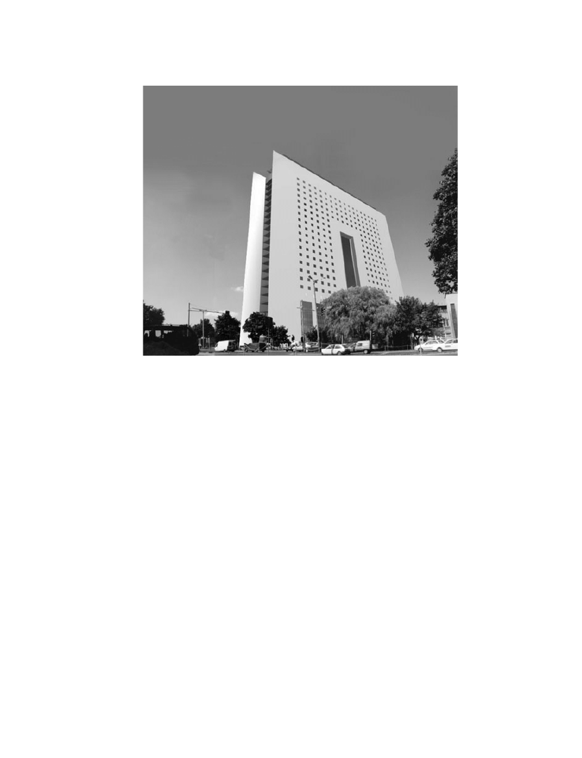
The paper presents results of the seismic analysis based on the above-mentioned method. The subject
of the analysis is the tall building, designed originally in Pozna´n, which is stiffened by the system of
coupled shear walls. This building is called, because of its elevation shape and its location in the city,
the ‘South Gate’ (see Figure 1). It is a multifunctional office centre with a heliport on the top.
After multi-variant static analyses the possibility of seismic location of the designed structure was
taken into account. Seismic analysis was carried out by means of the response spectrum technique
using the DAMB program (Wdowicki et al., 1995b), as part of an integrated system (Wdowicki
et al., 1995a). The design spectrum for elastic analysis according to Eurocode 8, Draft No. 6 (PrEN
THE STRUCTURAL DESIGN OF TALL AND SPECIAL BUILDINGS
Struct. Design Tall Spec. Build. 14, 59–67 (2005)
Published online 14 October 2004 in Wiley Interscience (www.interscience.wiley.com). DOI:10.1002/tal.261
Copyright © 2004 John Wiley & Sons, Ltd.
Received December 2003
Accepted March 2004
* Correspondence to: Jacek Wdowicki, Institute of Structural Engineering, Poznan University of Technology, ul. Piotrowo 5,
60-965 Poland. E-mail: jacek.wdowicki@put.poznan.pl
1998-1:200X, 2003) was used. To meet the requirements of damage limitation according to Eurocode
8 the allowable design ground acceleration was evaluated.
2.
BUILDING DESCRIPTION
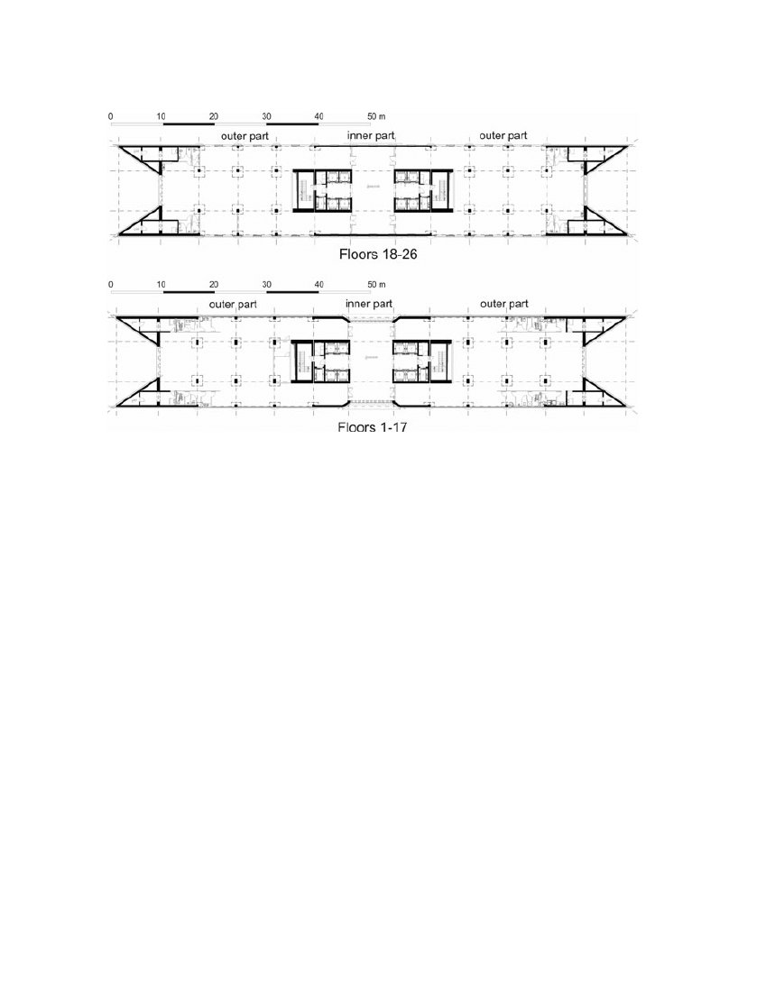
The ‘South Gate’ is designed as a fully smart building designed by the inverse method. The whole
structure is divided by movement joints into three parts: two symmetrical outer parts and one inner
part, because of the building length (about 100 m). The stiffness of each part is designed from the
equilibrium of deflection of each one. The floor layouts of the analysed building are shown in
Figure 2.
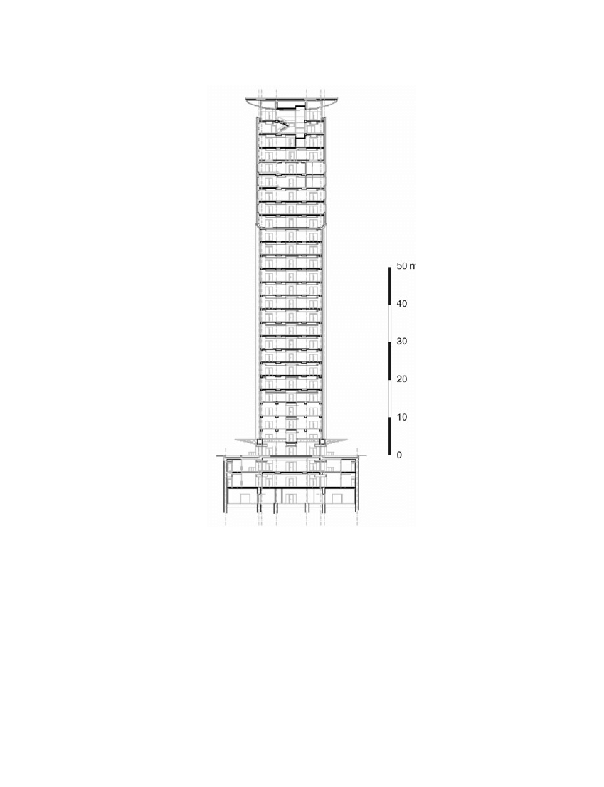
The total height of the building is 108·6 m. The main structure is the RC flat slab and column system
with shear walls and cores. The columns are on a grid of 7·5
¥ 7·8 m or 7·5 ¥ 4·65 m. There are three
basement floors and 26 floors above the ground (see Figure 3). Shear walls and cores will be con-
structed in RC, 0·7 to 0·3 m in thickness. They will be slip formed. Continuous floor RC slabs sup-
ported on columns have a depth of 0·20–0·35 m. The pin connections between columns and slabs have
been designed. RC elements are assumed as B50 (concrete grade) and material properties are taken
to be E
= 38·6 GPa, G = 16·54 GPa. The ground at the site in Pozna´n basically consists of stiff sandy
clay and medium-dense sand. The foundation system under the slab–column part is the slab founda-
tion with a depth of 0·8–1·5 m, but due to bearing capacity of the soil the foundation system under
shear walls and cores is based on RC diaphragm walls and barrettes. External basement walls are also
diaphragm walls.
60
E. M. WDOWICKA ET AL.
Copyright © 2004 John Wiley & Sons, Ltd.
Struct. Design Tall Spec. Build. 14, 59–67 (2005)
Figure 1. Analysed building: the South Gate
3.
MODEL AND THEORETICAL BACKGROUND OF ANALYSIS
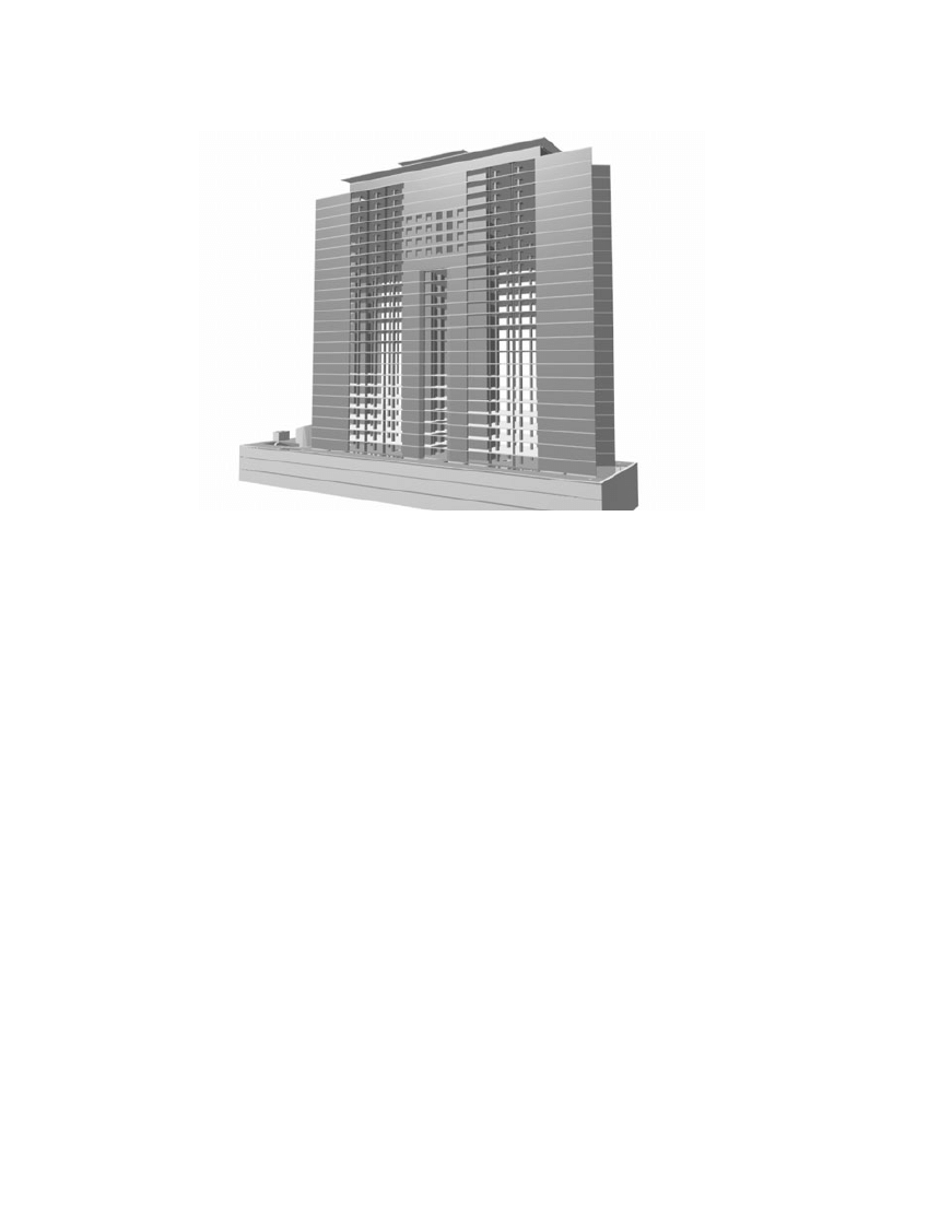
In the analysed building, lateral loads that arise as a result of winds and earthquakes are resisted by
the three-dimensional system of coupled shear walls (see Figure 4). A single wall or a group of walls
joined in a monolithic way composes a 3D shear wall. The considered shear walls are of the same
height. They are joined by connecting beam bands. The structural properties of shear walls and lintels
are uniform along the building height. A diaphragm action of all floor slabs is taken into considera-
tion as the effect of their in-plane infinite rigidity and negligible transverse one. Owing to the height-
to-width ratio of the shear walls, there is a possibility of treating each wall as an open thin-walled
beam, according to Vlasov theory assumptions.
The static analysis was carried out on the basis of some variant of the continuous connection method
(Wdowicki and Wdowicka, 1993). In the continuous connection method lintel beams are treated as
the equivalent shear connection medium between shear walls, while the walls are simply regarded as
vertical cantilevers. The technique may be used for both plane and spatial structures, which are essen-
tially regular in form throughout the height. The solution has the merit of being independent of the
number of storeys involved and, in fact, the accuracy increases as the number of storeys rises.
Dynamic solutions have been obtained by treating the structure as a lumped parameter system with
discrete masses in the form of rigid floor slabs arbitrarily located along the height, having flexural and
torsional inertia (Wdowicki et al., 1984). A dynamic model with masses in the form of rigid floor slabs
has been adopted, since over a half of building total mass is concentrated on the floor levels. Coupled
torsional-flexural vibrations have been considered because the torsional response of buildings during
ambient and earthquake response is significant (Hart et al., 1975). For shear wall multistorey struc-
ture it is more natural to determine the flexibility matrix D than stiffness matrix K. The vibration of
a structure is described by the following relation (Clough and Penzien, 1993):
SEISMIC ANALYSIS OF THE ‘SOUTH GATE’
61
Copyright © 2004 John Wiley & Sons, Ltd.
Struct. Design Tall Spec. Build. 14, 59–67 (2005)
Figure 2. Floor layouts of the South Gate
(1)
where D, M and C are flexibility, mass and damping matrices, respectively; x is the d-element vector
of generalized coordinates; d is the number of dynamic degrees of freedom of the calculated struc-
ture; and F is the d-element vector of generalized excitation forces, corresponding to generalized
coordinates.
Calculations were made using the DAMB program (Dynamic Analysis of Multistorey Buildings)
(Wdowicki et al., 1995b), which provides the possibility of performing linear dynamic analysis of 3D
shear wall structures.
DMx DCx x
DF
˙˙
˙
+
+ =
62
E. M. WDOWICKA ET AL.
Copyright © 2004 John Wiley & Sons, Ltd.
Struct. Design Tall Spec. Build. 14, 59–67 (2005)
Figure 3. Cross-section of the South Gate
The flexibility matrix D is generated from the exact solution of the governing differential equation
for a 3D continuous model. Also mass matrix is generated exactly according to the real distribution
of walls, connecting beams and floor slabs and including flexural and torsional inertia. The seismic
response of the structure is estimated using the response spectrum technique. The steps involved are
as follows:
(1) determination of natural frequencies and mode shapes;
(2) evaluation of modal participation factors and calculation of modal loading on the structure (using
an appropriate design spectrum);
(3) determination of response estimate taking into account the contribution from the given number of
modes for various parameters of interest (using three methods: SRSS—the square root of the sum
of the squares; CQC—the complete quadratic combination; and DSC—the double sum combina-
tion (Maison et al., 1983)).
4. RESULTS OF THE SEISMIC ANALYSIS
As a result of the first calculation step by DAMB, periods and corresponding mode shapes for the
outer part of the building have been received. The periods of the first 10 modes are summarized in
Table 1.
In the analysed case, frequencies of the first two translational modes are closely spaced. When the
modal responses for different modes are coupled, according to Eurocode 8 a more accurate procedure
than the SRSS method for the combination of the modal maxima will be adopted. Our previous analy-
sis serves as the basis of choosing the CQC method (Wilson et al., 1981).
SEISMIC ANALYSIS OF THE ‘SOUTH GATE’
63
Copyright © 2004 John Wiley & Sons, Ltd.
Struct. Design Tall Spec. Build. 14, 59–67 (2005)
Figure 4. 3D structural system of analysed building

According to guidelines from Eurocode 8, the minimum number k of modes to be considered in a
spatial analysis should satisfy the following conditions:
where k is the number of modes considered; n is the number of storeys above ground; and T
k
is the
period of vibration of mode k.
From the first condition
and from the second k
= 8. Finally, k = 16 was used for
the calculation. It was found that relative differences of results, in comparison to the results obtained
with regard to all considered modes (k
= 87), was less than 10
-4
.
The analysis was based on damage limitation state, according to Eurocode 8. According to (PrEN
1998-1:200X, 2003), the structure shall be designed and constructed to withstand a seismic action
having a larger probability of occurrence than the design seismic action, without the occurrence of
damage and the associated limitations of use, the costs of which would be disproportionately high in
comparison with the costs of the structure itself. The requirement of damage limitation is accomplished
by Eurocode 8, when interstorey drifts do not exceed to following values:
(a) for buildings having non-structural elements of brittle materials attached to the structure:
(b) for buildings having ductile non-structural elements:
(c) for buildings having non-structural elements fixed in a way as not to interfere with structural
deformations:
where h is the storey height; v is the reduction factor to take into account the lower return period of
the seismic event associated with the serviceability limit state; and d
r
is the design interstorey drift,
evaluated as the difference of the average lateral displacements at the top and bottom of the storey
under consideration and calculated according to 4.3.4 from Eurocode 8 (PrEN 1998-1:200X, 2003).
d v
h
r
£ ◊
0 01
d v
h
r
£ ◊
0 0075
d v
h
r
£ ◊
0 005
k
≥
=
◊
3 26
15 3
,
k
n
T
s
k
≥
£ ◊
3
0 2
and
64
E. M. WDOWICKA ET AL.
Copyright © 2004 John Wiley & Sons, Ltd.
Struct. Design Tall Spec. Build. 14, 59–67 (2005)
Table 1. Natural periods of the left part of the building
Mode number
Natural period [s]
Dominant direction
1
3·56536
First mode N–S
2
3·15713
First mode E–W
3
1·54929
First torsional mode
4
0·69140
Second mode N–S
5
0·50211
Second mode E–W
6
0·35925
Second torsional mode
7
0·26052
Third mode N–S
8
0·18108
Third mode E–W
9
0·14363
Third torsional mode
10
0·13635
Fourth mode N–S

The displacements induced by the design seismic action shall be calculated on the basis of the elastic
deformation of the structural system by means of the following simplified expression:
(2)
where d
s
is the displacement of a point of the structural system induced by the design seismic action;
q
d
is the displacement behaviour factor, assumed equal to q unless otherwise specified; and d
e
is the
displacement of the same point of the structural system, as determined by a linear analysis based on
the design response spectrum.
For the analysed building the importance category II according to Eurocode 8 may be assumed,
corresponding to buildings whose seismic resistance is of importance in view of the consequences
associated with a collapse (e.g. schools, assembly halls). For this importance category the importance
factor
g
1
= 1·2 and the reduction factor n = 0·4.
Assuming that specific provisions for all structural elements shall be satisfied to provide the appro-
priate amount of ductility (see 5.4–5.6 of PrEN 1998-1:200X, 2003), the ductility class DCM (medium
ductility) has been established. The corresponding value of behaviour factor q
= 3·3 has been applied.
It has been assumed that the analysed building may have non-structural elements of brittle materials
attached to the structure. In effect the following limit of maximum interstorey drift index has been
obtained:
where
Dde is the difference of lateral displacements at the top and bottom of the storey, determined
by a linear analysis based on the design response spectrum.
According to Chaallal et al. (1996) a drift index of 0·5% corresponds to the onset of damage in
non-structural components.
In the analysis the design spectrum for linear analysis according to Eurocode 8 has been taken. The
type 1 spectrum and subsoil class C (S
= 1·15, T
B
= 0·2, T
C
= 0·6, T
D
= 2·0) have been considered. A
value of viscous damping ratio
x = 5% has been assumed. The analysis has been carried out for the
design ground acceleration a
g
= 2·5 m/s
2
and seismic wave direction parallel to the y-axis (N–S). At
the mass matrix generation half of the variable load has been applied.
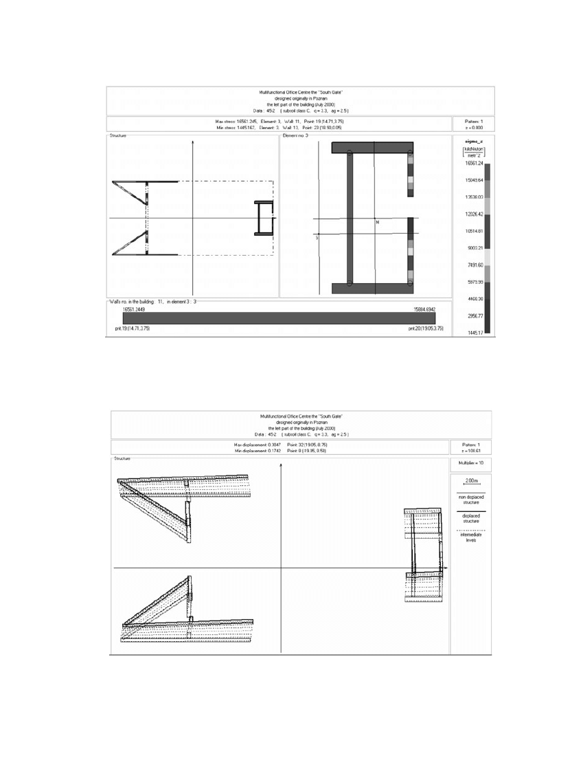
The results of the analysis carried out on the left outer part of the building, based on the response
spectrum technique, are shown in Figures 5 and 6.
The obtained maximum value of interstorey drift index was equal to 0·361%
< 0·379%. On this
basis it can be stated that for values of design ground acceleration less than 2·5 m/s
2
the analysed shear
wall structure satisfies the requirements for deformation limits in damage limitation state according
to Eurocode 8.
5.
CONCLUSIONS
In this study the seismic analysis of a shear wall tall building has been carried out using a continu-
ous–discrete approach and the response spectrum technique. The results of the analysis indicate that
the analysed building having sufficient stiffness against lateral loads arising from wind meets require-
ments of Eurocode 8 in damage limitation state for values of design ground acceleration less than
2·5 m/s
2
. It can be noted that in the method applied the preparation of data is easy and the length of
computation time is short. Consequently, the software based on this method represents a useful
tool for design analysis.
Dde
h
q
v
d
£
◊
◊
=
◊
◊ ◊ ◊
= ◊
0 005
0 005
3 3 0 4
0 379
%
d
q
d
s
d
e
=
◊
SEISMIC ANALYSIS OF THE ‘SOUTH GATE’
65
Copyright © 2004 John Wiley & Sons, Ltd.
Struct. Design Tall Spec. Build. 14, 59–67 (2005)
66
E. M. WDOWICKA ET AL.
Copyright © 2004 John Wiley & Sons, Ltd.
Struct. Design Tall Spec. Build. 14, 59–67 (2005)
Figure 5. Normal stresses at the base of shear wall structure in the left part of the building
Figure 6. Horizontal displacements of shear wall structure in the left part of the building

REFERENCES
Aksogan O, Arslan HM, Choo BS. 2003. Forced vibration analysis of stiffened coupled shear walls using con-
tinuous connection method. Engineering Structures 25(4): 499–506.
Chaallal O, Guizani L, Malenfant P. 1996. Drift-based methodology for seismic proportioning of coupled shear
walls. Canadian Journal of Civil Engineering 23: 1030–1040.
Clough RW, Penzien J. 1993. Dynamics of Structures. McGraw-Hill: New York.
Hart GC, DiJulio RM Jr, Lew M. 1975. Torsional response of high-rise buildings. Journal of the Structural Divi-
sion, Proceedings of the ASCE 101(ST2): 397–416.
Li G-Q, Choo BS. 1996. A continuous–discrete approach to the free vibration analysis of stiffened pierced walls
on flexible foundations. International Journal of Solids and Structures 33(2): 249–263.
Maison BF, Neuss CF, Kasai K. 1983. The comparative performance of seismic response spectrum combination
rules in building analysis. Earthquake Engineering and Structural Dynamics 11(5): 623–647.
PrEN 1998-1:200X. 2003. Eurocode 8: Design of Structures for Earthquake Resistance. Part 1: General Rules,
Seismic Actions and Rules for Buildings. DRAFT No. 6. Version for translation (Stage 49). CEN, Bruxelles;
January 2003.
Stafford-Smith B, Coull A. 1991. Tall Building Structures: Analysis and Design. Wiley: New York.
Wdowicki J, Wdowicka E. 1991. Integrated system for analysis of three-dimensional shear wall structures. Com-
putational Methods in Civil Engineering 1(3–4): 53–60.
Wdowicki J, Wdowicka E. 1993. System of programs for analysis of three-dimensional shear wall structures.
Structural Design of Tall Buildings 2(4): 295–305.
Wdowicki J, Wdowicka E, Wrze´sniowski K. 1984. Free vibration of unsymmetrical multistorey shear wall build-
ings. In Proceedings of the Third International Symposium on ‘Wall Structures’, vol. II. CIB, Warsaw, Poland;
339–346.
Wdowicki J, Wdowicka E, B´laszczy´nski T. 1995a. Integrated system for analysis of shear wall tall buildings. In
Proceedings of the Fifth World Congress ‘Habitat and High-Rise: Tradition and Innovation’. Council on Tall
Buildings and Urban Habitat, Amsterdam; 1309–1324.
Wdowicki J, Wdowicka E, B´laszczy´nski T. 1995b. System of programs for dynamic analysis of shear wall tall
buildings. In Proceedings of the International Conference on ‘Lightweight Structures in Civil Engineering’.
Warsaw University of Technology, Warsaw, Poland; 440–445.
Wilson EL, Der Kiureghian A, Bayo EP. 1981. A replacement for the SRSS method in seismic analysis. Earth-
quake Engineering and Structural Dynamics 9: 187–194.
SEISMIC ANALYSIS OF THE ‘SOUTH GATE’
67
Copyright © 2004 John Wiley & Sons, Ltd.
Struct. Design Tall Spec. Build. 14, 59–67 (2005)
Wyszukiwarka
Podobne podstrony:
SEISMIC ANALYSIS OF THE SHEAR WALL DOMINANT BUILDING USING CONTINUOUS-DISCRETE APPROACH
The algorithm of solving differential equations in continuous model of tall buildings subjected to c
An%20Analysis%20of%20the%20Data%20Obtained%20from%20Ventilat
Analysis of the Persian Gulf War
Analysis of the Holocaust
Analysis of the Infamous Watergate Scandal
Road Not Taken, The Extensive Analysis of the Poem
Analysis of the End of World War I
Night Analysis of the Novel
Preliminary Analysis of the Botany, Zoology, and Mineralogy of the Voynich Manuscript
Victory, The Analysis of the Poem
Analysis of Police Corruption In Depth Analysis of the Pro
Analysis of the First Crusade
Babi Yar Message and Writing Analysis of the Poem
Crime and Punishment Analysis of the Character Raskol
Legalization of Drugs Extensive Analysis of the?bate
Hospital Window, The Analysis of the Poem
Death of a Salesman Analysis of the Character Willy
Taming of the Shrew, The General Analysis of the Play
więcej podobnych podstron