
I:\CIRC\MSC\913.WPD
INTERNATIONAL MARITIME ORGANIZATION
E
4 ALBERT EMBANKMENT
LONDON SE1 7SR
Telephone: 0171-735 7611
Fax:
0171-587 3210
Telex:
23588 IMOLDN G
IMO
Ref. T4/4.01
MSC/Circ.913
4 June 1999
GUIDELINES FOR THE APPROVAL OF FIXED WATER-BASED LOCAL APPLICATION
FIRE-FIGHTING SYSTEMS FOR USE IN CATEGORY A MACHINERY SPACES
1
The Maritime Safety Committee, at its seventy-first session (19 to 28 May 1999), approved
Guidelines for the approval of fixed water-based local application fire-fighting systems for use in
category A machinery spaces, as set out in the annex.
2
Member Governments are requested to apply the annexed Guidelines when approving fixed
water-based local application fire-fighting systems for use in category A machinery spaces.
***


MSC/Circ.913
I:\CIRC\MSC\913.WPD
ANNEX
GUIDELINES FOR THE APPROVAL OF FIXED WATER-BASED LOCAL APPLICATION
FIRE-FIGHTING SYSTEMS
1
General
Fixed water-based local application fire-fighting systems should provide localized fire suppression
in areas, as specified in SOLAS regulation II-2/7.7 for category A machinery spaces, without the necessity
of engine shut-down, personnel evacuation, shutting down of forced ventilation fans or the sealing of the
space.
2
Definitions
2.1
Fire suppression: A reduction in heat output from the fire and control of the fire to restrict its
spread from its seat and reduce the flame area.
2.2
Water-based extinguishing medium: Fresh water or sea water with or without additives mixed
to enhance fire-extinguishing capability.
3
Principal requirements for the system
3.1
The system should be capable of manual release.
3.2
The activation of the fire-fighting system should not result in loss of electrical power or reduction
of the manoeuvrability of the ship.
3.3
The system should be capable of fire suppression based on testing conducted in accordance with
the appendix to these guidelines.
3.4
The system should be capable of fire suppression with forced ventilation fans running and supplying
air to the protected area, or a method of automatically shutting air supply fans upon release of the system
should be provided to ensure that the fire-fighting medium is not dispersed.
3.5
The system should be available for immediate use and capable of continuously supplying
water-based medium for at least 20 minutes in order to suppress or extinguish the fire and to prepare for
the discharge of the main fixed fire-extinguishing system within that period of time.
3.6
The system and its components should be suitably designed to withstand ambient temperature
changes, vibration, humidity, shock, impact, clogging and corrosion normally encountered in machinery
spaces. Components within the protected spaces should be designed to withstand the elevated temperatures
which could occur during a fire. Components should be tested in accordance with the relevant sections of
appendix A of MSC/Circ.668, as amended by MSC/Circ.728.

MSC/Circ.913
ANNEX
Page 2
Pending the development of international standards acceptable to the Organization national standards as prescribed
*
by the Administration should be applied.
Where the Hazen-Williams Method is used, the following values of the friction factor "C" for different pipe types
**
which may be considered should apply:
Pipe type
C
Black or galvanised mild steel
100
Copper and copper alloys
150
Stainless steel 150
I:\CIRC\MSC\913.WPD
3.7
The system and its components should be designed and installed based on international standards
acceptable to the Organization , and manufactured and tested in accordance with the appropriate elements
*
of the Appendix to these guidelines.
3.8
The location, type and characteristics of the nozzles should be within the limits tested, as referred
to in paragraph 3.3. Nozzle positioning should take into account obstructions to the spray of the
fire-fighting system.
3.9
The electrical components of the pressure source for the system should have a minimum rating
of IP 54. Systems requiring an external power source need only be supplied by the main power source.
3.10
The piping system should be sized in accordance with a hydraulic calculation technique to ensure
**
availability of flows and pressures required for correct performance of the system.
3.11
The water supply for local application systems may be fed from the supply to a water-based main
fire-fighting system providing that adequate water quantity and pressure are available to operate both
systems for the required period of time. Local application systems may form a section(s) of a water-based
main fire-extinguishing system provided that all requirements of SOLAS regulation II-2/10 and these
guidelines, and MSC/Circ.668, as amended by MSC/Circ.728, are met, and the systems are capable of
being isolated from the main system.
3.12
The capacity and design of the system should be based on the protected area demanding the greatest
volume of water.
3.13
The operation controls should be located at easily accessible positions inside and outside the
protected space. The controls inside the space should not be liable to be cut off by a fire in the protected
areas.
3.14
Pressure source components of the system should be located outside of the protected areas.
3.15
A means for testing the operation of the system for assuring the required pressure and flow should
be provided.
3.16
Where automatically operated fire-fighting systems are installed, a warning notice should be
displayed outside each entry point stating the type of medium used and the possibility of automatic release.

MSC/Circ.913
ANNEX
Page 3
I:\CIRC\MSC\913.WPD
3.17
Operating instructions for the system should be displayed at each operating position.
3.18
Spare parts and operating and maintenance instructions for the system should be provided as
recommended by the manufacturer.
3.19
Nozzles and piping should not prevent access to engine or machinery for routine maintenance. In
ships fitted with overhead hoists or other moving equipment, nozzles and piping should not be located to
prevent operation of such equipment.

MSC/Circ.913
ANNEX
Page 4
I:\CIRC\MSC\913.WPD
APPENDIX
TEST METHOD FOR FIXED WATER-BASED LOCAL APPLICATION
FIRE-FIGHTING SYSTEMS
1
SCOPE
This test method is for evaluating the effectiveness of fixed water-based local application
fire-fighting systems. The test method verifies the design criteria for vertical and horizontal grids of
nozzles. The test method is intended to evaluate maximum nozzle spacing, minimum and maximum
distance from the nozzle to the hazard, minimum nozzle flow rate in addition to minimum and maximum
operating pressure.
2
SAMPLING
2.1
The nozzles and other system components should be supplied by the manufacturer with design and
installation criteria, operating instructions, drawings, and technical data sufficient for the identification of
the components.
2.2
The flow rate for each type and size of nozzle should be determined at the minimum and maximum
nozzle operating pressure.
3
FIRE TESTS
3.1
Test principles
3.1.1.
These tests are intended to evaluate the fire-extinguishing capabilities of individual nozzles and
grids of nozzles used as local application fire-fighting systems on light diesel oil fuel spray fires.
3.1.2
The tests also define the following design and installation criteria:
.1
maximum spacing between nozzles;
.2
minimum and maximum distance between the nozzles and the protected hazard;
.3
the need for nozzles to be positioned outside of the protected hazard; and
.4
minimum and maximum operating pressure.
3.2
Test description
3.2.1
Test enclosure
3.2.1.1 The test enclosure, if any, should be sufficiently large and provided with adequate natural or forced
ventilation during the fire test to ensure that the oxygen concentration at the fire location during the fire test
remains above 20% (by vol) without activation of the local application fire-fighting system.
3.2.1.2 The test enclosure, if any, should be at least 100 m in area. The height of the test enclosure should
2
be at least 5 m.

MSC/Circ.913
ANNEX
Page 5
I:\CIRC\MSC\913.WPD
3.2.2
Fire scenarios
3.2.2.1 The fire scenarios should consist of nominal 1 and 6 MW spray fires. These fires should be
produced using light diesel oil as the fuel as described in Table 3.2.2.1.
Table 3.2.2.1
Spray fire parameters
Spray nozzle
Wide spray angle (120° to
125°) full cone type
Wide spray angle (80°) full
cone type
Nominal oil pressure
8 Bar
8.5 Bar
Oil flow
0.16 ± 0.01 kg/s
0.03 ± 0.005 kg/s
Oil temperature
20 ± 5°C
20 ± 5°C
Nominal heat release rate
6 MW
1 MW
3.2.2.2 The fuel spray nozzles should be installed horizontally and directed toward the centre of the nozzle
grid.
3.2.2.3 The fuel spray nozzle should be located 1 m above the floor and at least 4 m away from the walls
of the enclosure, if any.
3.2.3
Installation requirements for tests
3.2.3.1 The local application system should consist of uniformly spaced nozzles directed vertically
downward.
3.2.3.2 The system should consist of either a 2 x 2 or 3 x 3 nozzle grid, as required.
3.2.3.3 The nozzles should be installed at least 1 m below the ceiling of the enclosure, if any.
3.2.3.4 The maximum spacing of the nozzles should be in accordance with the manufacturers system
design and installation manual.
3.3
Test programme
3.3.1
The fire-extinguishing capabilities of the system should be evaluated for the minimum and
maximum separation distances (the distance between the nozzle grid and the fuel spray nozzle). These
distances should be as defined in the manufacturers system design and installation manual.
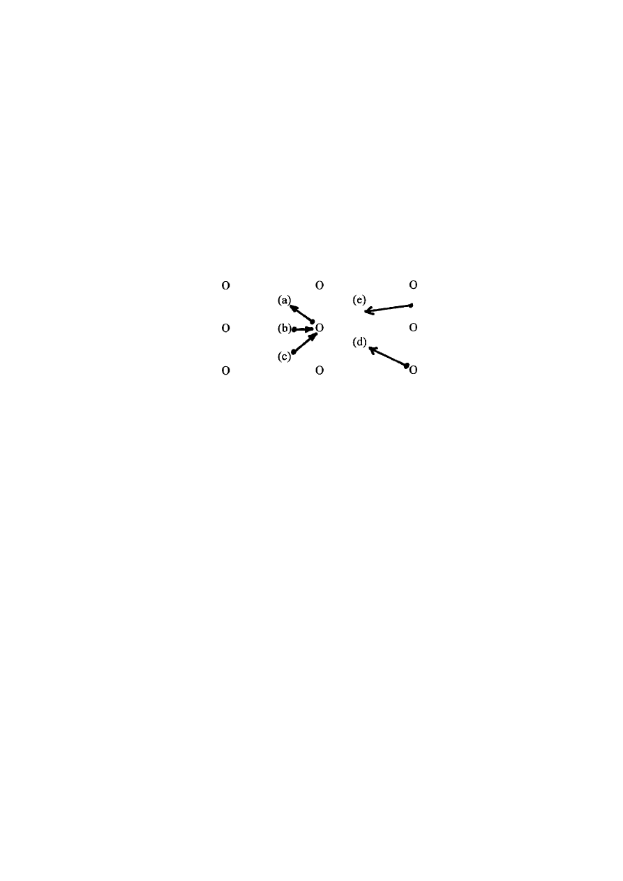
3.3.2
Each separation distance should be evaluated against the two fire scenarios (1 and 6 MW spray
fires). Tests should be conducted with the fuel spray nozzles horizontally positioned in the following
locations:
.1
under one nozzle in the centre of the grid;
.2
between two nozzles in the centre of the grid;
MSC/Circ.913
ANNEX
Page 6
I:\CIRC\MSC\913.WPD
.3
between four nozzles;
.4
under one nozzle at the edge of the grid (corner); and
.5
between two nozzles at the edge of the grid.
These fire locations are shown in figure 3.3.2.
Figure 3.3.2
Fuel spray nozzle locations
O
Water nozzle locations
ö
ö
Fuel spray nozzle location and direction
( )
Test designation
3.4
Test results and interpretation
3.4.1
The local application fire-fighting system is required to extinguish the test fires within 5 minutes
from the start of water discharge. If the fire re-ignites after this five minute water discharge period the test
is considered to be a failure.
3.4.2
The results of the tests should be interpreted as follows:
.1
Systems (utilizing a 3 x 3 nozzle grid) that extinguish fires referred to in 3.3.2.1 to 3.3.2.3
are considered to have successfully completed the protocol with the condition that the outer
nozzles should be installed outside of the protected area a distance of at least 1/4 of the
maximum nozzle spacing.
.2
Systems (utilizing either a 2 x 2 or 3 x 3 nozzle grid) that extinguish fires referred to in
3.3.2.3 to 3.3.2.5 are considered to have successfully completed the protocol and can be
designed with the outer nozzles located at the edge of the protected area. This does not
prohibit the location of the nozzles outside of the protected area.
.3
The requirements stated in either 3.4.2.1 or 3.4.2.2 should be met for both the minimum
and maximum separation distances as well as the minimum and maximum operating
pressures.
.4
For installations which may be adequately protected using individual nozzles or a single
row of nozzles, the effective nozzle coverage (width and length) is defined as 1/2 the
maximum nozzle spacing.

MSC/Circ.913
ANNEX
Page 7
I:\CIRC\MSC\913.WPD
4
TEST PROCEDURE
4.1
Pre-burn time
Each fuel oil spray should be ignited and allowed to burn for no more than 15 seconds prior to
system operation.
4.2
Measurements
4.2.1
Fuel oil spray system
4.2.1.1 The fuel oil flow rate and pressure in the fuel oil spray system should be verified prior to the test.
4.2.1.2 The fuel oil spray system pressure should be measured during the test.
4.2.2
Oxygen concentration at the fire location
Oxygen concentration should be measured at 100 mm below the fuel oil spray nozzle.
4.2.3
Water spray system pressure and flow rate
The system water pressure and flow rate should be measured using suitable equipment.
4.3
Operation of the fire-fighting system
4.3.1
The water spray system should be activated within the pre-burn time specified in section 4.1.
4.3.2
The water spray system should be operated for a minimum of one minute after fire extinguishment.
4.3.3
The fires should be extinguished within the 5 minutes of water application.
4.3.4
The fuel oil spray should be operated for at least 15 seconds after fire extinguishment.
4.4
Observations during the fire test
During the test, following observations should be recorded:
.1
start of the ignition procedure;
.2
start of the test (ignition);
.3
time when the extinguishing system is activated;
.4
time when the fire is extinguished;
.5
time when the extinguishing system is shut off;
.6
time of re-ignition;
.7
time when the fuel supply to the nozzle is stopped; and
.8
time when the test is terminated.

MSC/Circ.913
ANNEX
Page 8
I:\CIRC\MSC\913.WPD
5
TEST REPORT
The test report should, as a minimum, include the following information:
.1
name and address of the test laboratory;
.2
date of issue and identification number of the test report;
.3
name and address of applicant;
.4
name and address of manufacturer or supplier of the product;
.5
test method and purpose;
.6
product identification;
.7
description of the tested product:
.1
assembly drawings;
.2
descriptions;
.3
assembly of included materials and components;
.4
specification of included materials and components;
.5
installation specification; and
.6
detailed drawings of the test set-up;
.8
date of tests;
.9
drawing of each fire test configuration;
.10
measured water spray nozzle flow characteristics;
.11
identification of the test equipment and used instruments;
.12
test results including observations and measurements made during and after the test:
.1
maximum nozzle spacing;
.2
minimum and maximum separation distances; and
.3
minimum and maximum operating pressures;
.13
deviations from the test method;
.14
conclusions; and
.15
date of the report and signature.
________

MSC/Circ.913
ANNEX
Page 9
I:\CIRC\MSC\913.WPD
Wyszukiwarka
Podobne podstrony:
APA practice guideline for the treatment of patients with Borderline Personality Disorder
Guidelines for the Management of Aneurysmal Subarachnoid Hemorrhage
ESTRO BOOKLET 5 Practical guidelines for the impletation of in vivo dosimetry with diodes in extern
guidelines for the content of rig move procedures sept 2008
Distributed Algorithm for the Layout of VP based ATM Networks
The American Society for the Prevention of Cruelty
[Pargament & Mahoney] Sacred matters Sanctification as a vital topic for the psychology of religion
International Convention for the Safety of Life at Sea
Microsoft Word MIC1 Guidelines for the Generat
Broad; Arguments for the Existence of God(1)
ESL Seminars Preparation Guide For The Test of Spoken Engl
Kinesio taping compared to physical therapy modalities for the treatment of shoulder impingement syn
GB1008594A process for the production of amines tryptophan tryptamine
Popper Two Autonomous Axiom Systems for the Calculus of Probabilities
więcej podobnych podstron