REAR
DIFFERENTIAL
-
ONE
TEN
...
.
...
,..
......
.
..,
.
.
.
.
OVERHAUL
REAR
AXLE
DIFFERENTIAL
ASSEMBLY (SALISBURY) LAND ROVER ONE TEN
MODELS
8. Remove
the
fixings and withdraw the differential
bearing caps.
Service tools:
47
screw press;
131
C axle spreader
or axle compressor GKN
131;
191
dial gauge, bracket and base;
1122
screw press;
1205spanner
for
drive coupling;
S
123 A
pinion bearing cup remover;
47
BK pinion bearing cone
47
BL differential bearing remover;
1122
G pinion bearing cup replacer;
134
DP differential bearing replacer;
P
setting gauge
for pinion height
or
191-4
universal setting block;
131
pegs for axle spreader;
RO 1008oil seal replacer
DISMANTLE
NOTE:
fixing bolts used
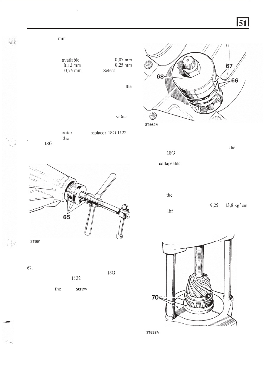
on the differential assembly
and differential cover have metric threads.
1.
Drain off
differential lubricating
oil,
and refit
2. Remove the rear axle assembly
vehicle.
3 .
Remove the hub driving
fixings.
4. Withdraw the driving
and axle shaft
sufficiently to disengage the differential.
5 . Repeat instruction
4
for the other axle shaft.
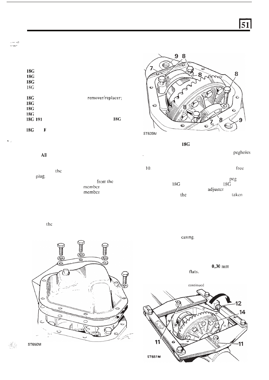
6. Remove the fixings and support strip at the
differential cover and withdraw the cover and
joint washcr.
7.
Note
relationship marking on the bearing caps
and axle casing to ensure correct refitting.
Using axle spreader
131
C
9. Clean out and examine the spreader tool
provided
in the gear casing face; ensure that the
holes are free from dirt and
burrs
and damage.
Ensure that the turnbuckle adjuster
is
to
turn.
11. Fit the axle spreadcr to engage the
holes.
Spreader
131
C, Adaptor pegs
131
F.
12.
Using a spanner, turn
t h e
until all free
play between
spreader and casing
is
up,
denoted by the adjuster becoming stiff to
t u r n .
13.
Check that the side members
of
the spreader are
clear of the casing.
14.
Stretch the casing, rotating the adjuster by one
flat at a time,
until
the differential assembly can
be levered out.
Do not lever against the spreadcr;
use suitablc packing under the levers to avoid
damage to the
CAUTION: To prevent permanent damage to the
gear carrier case, it must not be over-stretched.
Each flat on the turnbuckle
is
numbered to enable
a
check to be made on the amount turned. The
maximum stretch permitted is
(0.012
in),
equivalent to three
6
15. Ease off the adjuster and remove
t h e
spreader
7
REAR DIFFERENTIAL -ONE TEN
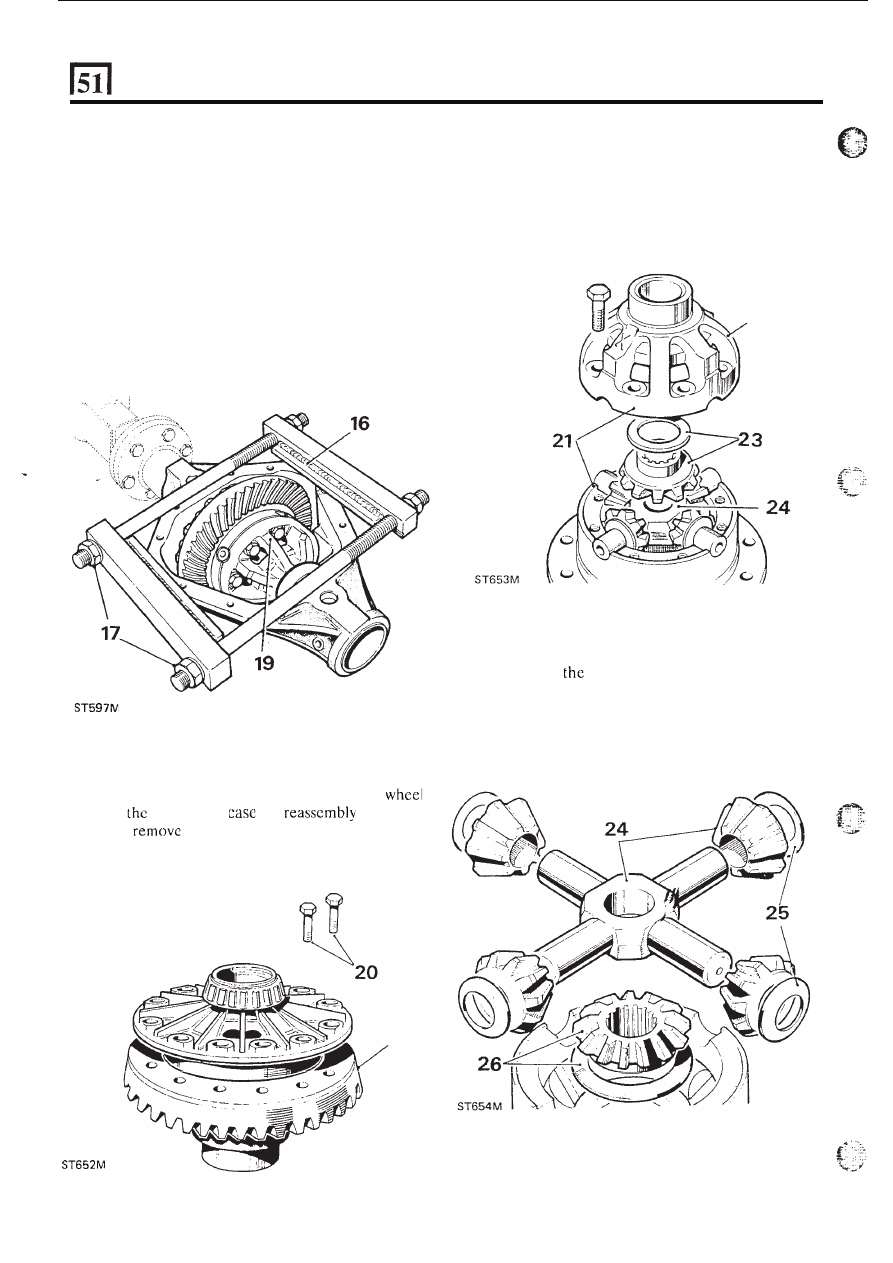
Using axle compressor
GKN
131
16. Place the tool on to t h e differential casing, as
illustrated,
with
t h e
weld
seam
uppermost.
Ensure that the plates rest squarely
on the
differential machined surface and the end bars
butt against the edges of the casing.
17. Tighten the adjusting nuts by hand only, until
all
slack is taken up.
18. Continue to tighten both nuts alternately with
a
spanner, one flat at a time, to a maximum of three
flats.
19. Carefully lever-out the differential assembly.
Dismantle differential
20. Add alignment
marks
between the crown
and
differential
for
purposes,
then
the fixings and withdraw the crown
wheel.
24.
Lift
out the cross-shaft and pinions.
25. Withdraw
four dished thrust washers.
26. Withdraw
the
lower differential wheel and thrust
washer.
continued
20
21. Note
t h e
alignment markings
on
the
two
22. Lift off the upper case.
23. Withdraw the upper differentiai wheei and thrust
differential casings
to
ensure correct refitting,
then remove the fixings.
washer.
22
8
REAR DIFFERENTIAL -ONE TEN
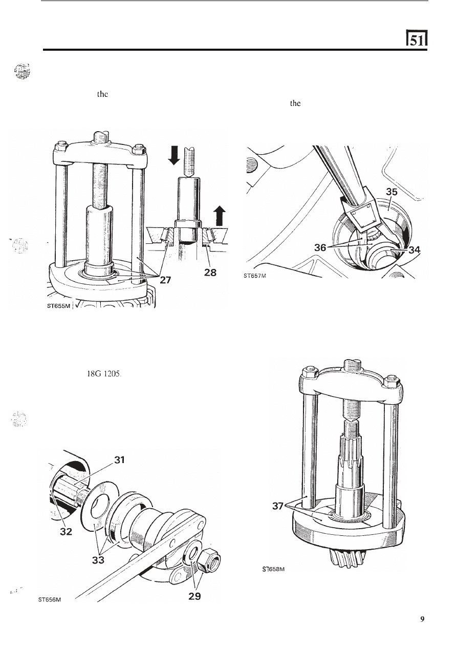
27. Remove the differential bearing cones using
remover
18G 47
BL
and adaptors 1 and 2 and
press 47.
28. Withdraw
shim washers fitted between the
bearing cones and the differential casings.
,
34. Withdraw
t h e
outer bearing cone.
35. Extract the pinion inner bearing cup and shim
washers from the casing. Note
t h e
shim washer
thickness. Remover
S
123 A .
36.
Extract
pinion outer bearing cup from the
casing. Remover
S
123
A .
Remove final drive pinion
29. Prevent the coupling flange from rotating
and
remove the flange locknut and plain washer.
Spanner
30. Support the drive pinion and remove the coupling
flange by tapping
with
a hide hammer.
31. Withdraw the drive pinion together with the inner
bearing cone.
32. Withdraw and discard the collapsable bearing
spacer.
33. Withdraw the oil seal, gasket and oil thrower.
....
...
...
.:
...
.
37. Remove the inner bearing cone from the pinion.
Remover
18G 47 R K and Press 47.
continued
REAR DIFFERENTIAL- ONE
T
EN
INSPECTION
38. Examine all components for obvious wear
or
damage.
39. The bearing cones must bc a press
fit
on
locations, except the
pinion flange and
bearing which is a slide fit.
40. The crown wheel and pinion are supplied as a
matched pair and must not be interchanged
separately.
A
new crown wheel and pinion matched pair may
be fitted to an original gear carrier casing
i f sound.
The original crown wheel and pinion, if sound,
may be fitted into a replacement casing.
41.
The
two parts of the differential unit casing arc
matched and must not be replaced separately.
42. Discard and renew all thrust washers.
43. Differential housings with worn thrust washer
seatings must be replaced as a pair.
face for burrs and damage which could lead
to
crown wheel run-out when fitted.
Examine the differential case to crown whecl joint
ASSEMBLE
.
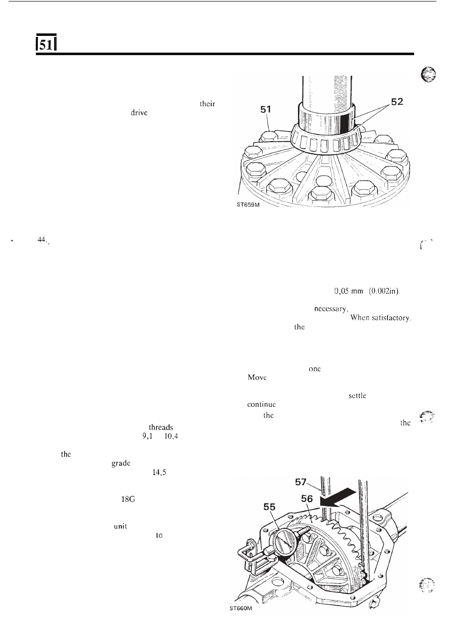
55.
Position a suitablc dial gauge indicator on the
casing with
t h e
stylus registering on the back face
of the crown wheel.
56. Rotate the differcntial
and chcck the total
indicated
run-out
on the crown wheel back facc.
This must not exceed
If
run-out is excessive, check the mating faces for
dirt and damage;
if
select a new radial
position for
t h e
crown wheel.
continue with
following check.
* -
Assemble differential unit
Differential bearing adjustment
45. Fit the differential lower wheel and thrust washer
to the differcntial case. Sec illustration following
instruction 23.
46. Fit the dished thrust washers.
47. Fit the cross-shaft and pinions.
48. Fit the differential upper wheel and thrust washer.
57. Insert two levers between the casing and the
differential
u n i t
at
side.
58.
the differcntial unit fully
to
one side of the
casing; do not
tilt
the unit.
59. Rotate the differential unit to
the bearings,
to lever the differential
to
the side, then
60. Lever
the
assembly fully to the other side
of
casing, rotate the
unit to
settle the bearings, then
note
t h e
total indicator reading.
49. Fit the differcntial upper case lining-up the marks.
zero
dial gauge indicator.
.
50. Secure the assembly
with
bolts using Loctite
'Studlock' grade
CVX on the
and tighten
evenly and diametrically to
to
kgf
m (66
to 75 Ibf
f t ) .
51. Fit
crown wheel to the differcntial casing. Use
Loctite 'Studlock'
CVX on the fixing bolt
threads and tighten
to
13
to
kgf m (95 to
105 Ibf
ft).
52. Prcss on
t h e
differential roller bearing cones less
shim washers, using
134
DP, and leave
t o
one side until required for instruction 96.
continued
53. Fit the bearing cups to the differential.
54.
Fit the differential
and bearings to the gear
carrier casing, and rotate unit
centralize the
bearings.
Do not fit the bearing caps.
10
REAR DIFFERENTIAL
-
ONE
TEN
61. Add 0,127
(0.005 in), for bearing pre-load, to
the total noted
in the preceding instruction. ‘The
sum is then equal to the nominal value of shims
required for the differential bearings:
Shims are
in
the
range
(0.003 in),
(0.005 in),
(0.010 in) and
(0.030 in).
the total
value
of
shims required.
62. Remove
t h e
differential
unit
and bearings and
place aside.
Do
not fit the shim washers until
subsequent ‘Differential backlash’ checks have
been made, instructions 96 to
102.
Fit
drive pinion
63. Select shim washers
of the same thickness
as
those removed from under the pinion inner cup,
instruction
35, and place ready for fitting.
64. Position the
bearing
G
detail
2,
and
outer bearing cup on the press
tool
1122.
65. Locate the assembly into the pinion housing nose.
’..
.
.
M
66. Place the selected shim washcrs on to
the
inner
bearing
cup seating.
Position
t h e inner
bearing cup in
the
casing.
68. Position the inner bcaring replaccr
1122 G
detail
1,
onto 18G
and secure with the fixing
nut.
69. Hold still
centre
and turn the butterfly
lever to draw
in the bearing cups.
70. Press the inner bearing cone onto
drive
71. Position the pinion and bearing
in the casing; omit
72.
Fit the outer bearing cone onto the pinion.
73.
Fit the coupling flange and plain washcr and
loosely
fit
the flange nut.
74. Tighten the coupling flange locknut to remove
end-float from
the
pinion.
75. Rotate
pinion to settle the bearings and slowly
tighten the flangc locknut. Use a spring balancc
to
obtain a torque resistance of
to
(8 to 12
in) to rotate
t h e
pinion.
pinion.
47
B K , details
1
and
2 and press 47.
the
spacer at this stage.
continued
I
E
11
RE
A
R
DIFFERENTI
AL
-ONE TEN
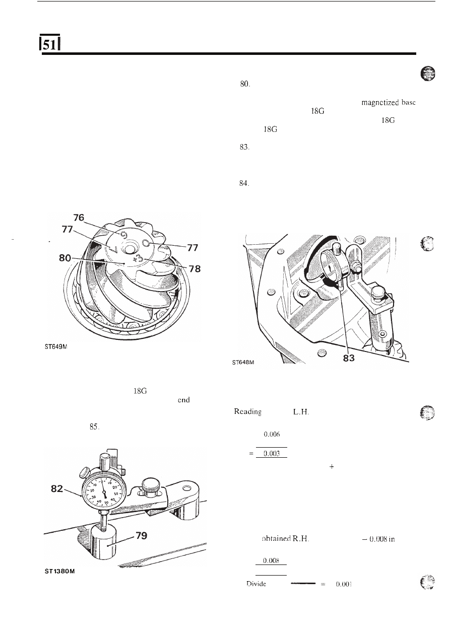
Drive pinion markings
76. Check that the serial number marked on the
pinion end face matches that marked on the
crown wheel,
77. The markings on the end face adjacent to the
serial number are of no significance during
servicing.
78. The figure marked on the end face opposite to the
serial number indicates,
in thousandths of an inch,
the deviation from nominal required to correctly
set the pinion. A pinion marked plus (+) must be
set below nominal, a minus (-) pinion must be set
above nominal. An unmarked pinion must be
set
at nominal.
Drive pinion adjustment
Ensure that the pinion end face is free
of raised
burrs around the etched markings.
81. Remove the keep disc from the
of dial gauge tool
191.
82. Place the dial gauge and setting gauge
191 P
or
191-4 on a flat surface and zero the dial
gauge stylus on to the setting gauge.
Position the dial gauge centrally on the pinion end
facc with the stylus registering on the lowest point
on one differential bearing bore. Note the dial
gauge deviation from the zeroed setting.
Repeat on the other bearing bore. Add together
the readings, then halve the sum to obtain the
mean reading. Note whether the stylus has moved
up or down from the zeroed setting.
-
88
79. The nominal setting dimension is represented by
the setting gauge block
191
P
or 18G 191-4,
which is referenced from the pinion
face to
the bottom radius
of the differential bearing bore.
The
latter
gauge
is
illustrated
following
instruction
Example 1
obtained
sidc
Reading obtained R . H . side
+
0.006 in
-
0.003
in
Add
+
in
-
0.003
in
+
i n
+
0.003
=
0.0015
in
Divide
b y 2
=
-
2
Therefore
subtract
0.0015 in from the shim thickness
behind the pinion inner bearing track.
Example
2
Reading obtained
L.H. side
+
0.006 in
Reading
side
Add
+
0.006
in
-
in
=
-
0.002
in
-
0.002
b y 2
=
-
in
2
continued
12
REAR DIFFERENTIAL -
ONE
TEN
.
,
t h e
stylus has moved down, the amount is
.
...
.
.,
.
.
equivalent to the thickness of shims that must be
removed from under the pinion inner cup to bring
t h e
pinion down to the nominal position.
t h e
has
up, the amount is
equivalent to the additional thickness of shims
required to bring the pinion up to the nominal
position.
..,
I -
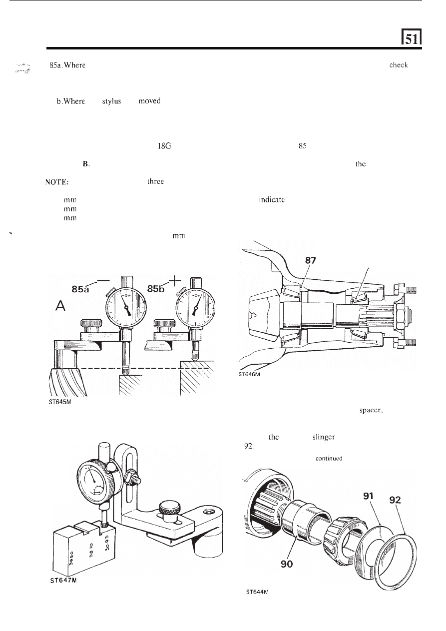
Illustration A.
Using setting gauge
191 P.
Illustration
Using universal setting block
18G 191-4
The setting block has
setting heights as
follows:
39.50
Rationalised axle
38.10
Pre-Rationalised axle
30.93
Salisbury axle
Ensure that the height marked
30.93
is used for
this differential.
E3
86.
Before adjusting the shim thickness,
the
pinion face marking and
if it has a plus (+) figure,
subtract that amount
in thousands of inch from
the shim thickness figure obtained
in the previous
instruction. Alternatively
if the pinion has
a minus
(-) figure, add t h e amount to the shim thickness
figure.
87. Adjust the shim thickness under the pinion inner
cup as necessary, by the amount determined
in
instructions
and
86.
88. Recheck the pinion height setting instructions 82
to 84. If t h e setting is correct,
mean reading on
the dial gauge will agree with the figure marked
on the pinion end face. For example, with an end
face marking of
+3, the dial gauge reading should
that the pinion is 0.003
in
below nominal.
89. When
the
pinion
setting
is
satisfactory,
temporarily remove
t h e
pinion outer bearing.
89
90. Fit a new collapsable bcaring
flared end
outward, to the drive pinion and refit the outer
bearing.
Fit
pinion oil
91
Fit the
oil
seal gasket.
13
REAR DIFFERENTIAL
-
ONE TEN
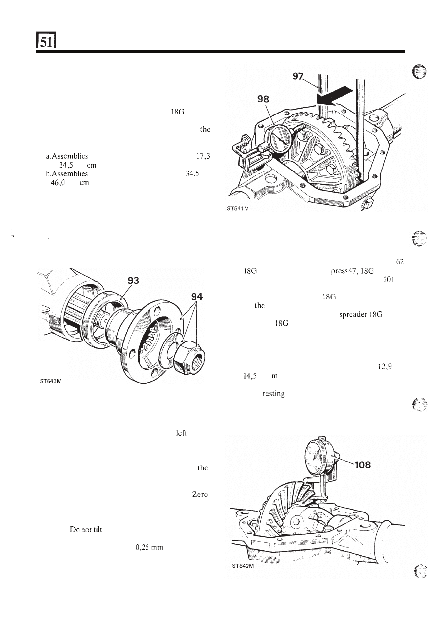
93. Fit the pinion
oil seal, lipped side first, using
general purpose grease
or, where available, a
molybdenum disulphide based grease
on the seal
lip, using R O 1008 to drift
in the seal.
94.
Fit the coupling flange and plain washer and
loosely
fit
a new flange nut. Secure
1205 to
the coupling flange, using slave fixings.
95. Alternately tighten the flange nut and check
drive pinion resistance to rotation until the
following figures arc achieved, as applicable:
re-using original pinion bearings:
to
kgf
(15 to 30 Ibf in).
with new pinion bearings:
to
kgf
(30 to 40 Ibf in).
NOTE:
Once the bearing spacer has started to
collapse the torque resistance build-up is rapid,
therefore check frequently, using a spring balance,
to ensure the correct figures are not exceeded,
otherwise a new collapsable bearing spacer will be
required.
Differential backlash checks
96. Pick
up
the differential unit
as
after
instruction
52.
97. Fit the differential
u n i t
and lever the unit away
from the drive pinion until
t h e
opposite bearing
cup is seated against the housing. Do not tilt
unit.
98. Install a dial gauge on the casing
with
its stylus
resting
on the back face
of
the crown wheel.
the gauge.
99. Lever the differential unit
to engage the crown
wheel teeth in full mesh with the drive pinion
teeth.
t h e
unit.
100. Note the total reading obtained on the dial gauge.
101. From this figure subtract
(0.010 in) to
obtain the correct crown wheel backlash
w h e n
fitted. The result indicates the value of shimming
to be fitted between the differential case and the
bearing cone at the crown wheel side of the
differential.
14
102.
Fit
the shim value determined in instruction 101,
taking
the
shims from
the pack previously
determined
during
‘Differential
bearing
adjustment’ checks, instructions 57
to
47 BL details
I and 2,
134 DP.
103. Fit the remaining shims from instruction
to
the
opposite side o f the differential.
18G 47 BL
details
1
and 2, press 47,
134
DP.
104.
Fit
differential unit with shims and bearings to
the axle casing, using t h e axle
131
C
with pegs
131 F.
105. Remove the axle spreader.
106.
Fit the bearing caps
in
their correct position,
referring to the relationship markings on the caps
and on the axle casing.
107. Tighten the bearing caps fixings to
to
kgf
(93 to 105 Ibf
ft).
108. Mount a dial gauge on the axle casing with the
stylus
o n
a crown wheel tooth.
continued
REAR DIFFERENTIAL
-
ONE TEN
109. Prevent the drive pinion from rotating and check
the
crown wheel backlash which must be
to
(0.006 to 0.011 in). If the backlash is not
within the specified limits, repeat the differential
backlash checks, instructions 96 to 102 looking for
possible errors.
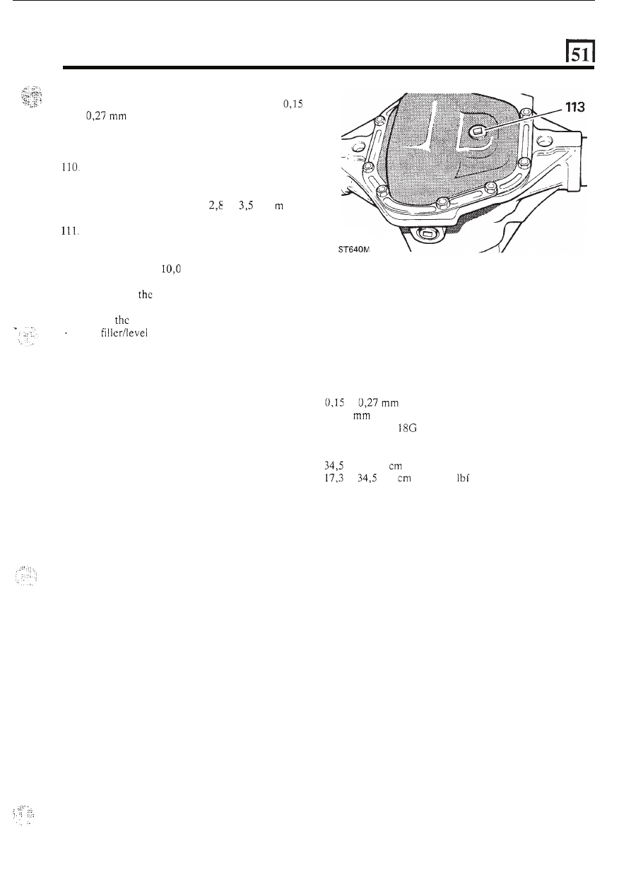
Fit the differential cover and new gasket, coating
both sides of the gasket with Hylomar PL 32M or
an equivalent non-setting sealant.
Torque load for fixings is
to
kgf
(20 to
25 Ibf ft).
Reverse instructions
3
to
5 and coat t h e threads
of
the hub driving member bolts with Loctite
‘Studlock’ grade CVX and
fit
and tighten the bolts
evenly. Torque:
kgf
m
(73 Ibf ft).
112. Fit the rear axle assembly to
the vehicle.
113. Replenish
differential lubricating oil, (see
Lubrication chart). After the initial axle run,
check
oil level and replenish as necessary to
114. Where major running parts have been replaced
during servicing,
it
is a recommended practice to
allow
t h e
axle assembly to ‘run in’ by avoiding,
where possible, heavy loads and high speeds
the
plug hole.
during initial running.
DATA
Crown wheel backlash .........................................
Differential bearings pre-load
................................
Pinion height setting
............................................
to
(0.006 toO.O1l in)
0,127
(0.005 in)
Set using gauge
191 P or
18G 191-4
Torque resistance initial setting figures
Torque to turn drive pinion and new pinion bearings
...
Torque
to
tum
drive pinion re-using the original bearings
.
to 46 kgf
(30
to
40
Ibf in)
to
kgf
(15
to
30
in)
15
Wyszukiwarka
Podobne podstrony:
Land Rover Freelander 2005
Pin out edc15 LAND ROVER BMW (2)
LAND ROVER FREELANDER 2002 2003
land rover filtr paliwa
land rover kontroka silnika
land rover freelander
akumulator do land rover defender ld 25 90 110 tdi
akumulator do land rover land rover discovery ii 39 v8 25 d 2
akumulator do land rover land rover defender hard top ld 25 90
akumulator do land rover land rover hard top 23 d
Land Rover Discovery 1989 1997
land rover defender brak mocy
akumulator do land rover land rover hard top 23
akumulator do land rover freelander ln 18i 16v
akumulator do land rover land rover sport 27 tdvm 36 td 8 42 44
akumulator do land rover land rover discovery i 35
więcej podobnych podstron