
NA to BS EN 1991-2:2003
UK National Annex to
Eurocode 1: Actions on
structures –
Part 2: Traffic loads on bridges
ICS 91.010.30; 93.040
NO COPYING WITHOUT BSI PERMISSION EXCEPT AS PERMITTED BY COPYRIGHT LAW
NATIONAL ANNEX
Incorporating
Corrigendum No. 1
Licensed copy: BSI USER 06 Document Controller, Midmac Contracting Co. W.L.L, Version correct as of 14/10/2010
12:11, (c) BSI

Publishing and copyright information
The BSI copyright notice displayed in this document indicates when the
document was last issued.
© BSI 2008
ISBN 978 0 580
63216 7
The following BSI references relate to the work on this standard:
Committee reference B/525
Draft for comment
06/30128340/DC
Publication history
First published May 2008
Amendments/corrigenda issued since publication
Amd. no.
Date
Text affected
Cor 1
May 2008
‘‘Timber’’ removed from title
NA to BS EN 1991-2:2003
Licensed copy: BSI USER 06 Document Controller, Midmac Contracting Co. W.L.L, Version correct as of 14/10/2010
12:11, (c) BSI

© BSI 2008 •
i
NA to BS EN 1991-2:2003
Contents
Introduction 1
NA.1
Scope 1
NA.2
Nationally determined parameters 2
NA.3
Decision on the status of informative annexes 45
NA.4
References to non-contradictory complementary
information 46
Bibliography 47
List of figures
Figure NA.1 – Basic longitudinal configuration of SV model vehicles 5
Figure NA.2 – Basic longitudinal configuration of SOV model
vehicles 7
Figure NA.3 – Lateral wheel arrangement for trailer axles of all SOV
models 9
Figure NA.4 – Typical application of SV or SOV and Load Model 1
loading when the SV or SOV vehicle lies fully within a notional lane 11
Figure NA.5 – Typical application of SV or SOV and Load Model 1
loading when the SV or SOV vehicle straddles two adjacent lanes 11
Figure NA.6 – Vehicle model for abutments and wing walls 22
Figure NA.7 – Effective span calculation 27
Figure NA.8 – Relationships between k(f
v
) and mode
frequencies f
v
27
Figure NA.9 – Reduction factor, *, to allow for the unsynchronized
combination of pedestrian actions within groups and crowds 28
Figure NA.10 – Response modifiers 31
Figure NA.11 – Lateral lock-in stability boundaries 33
Figure NA.12 – Flow chart for determining whether a dynamic analysis
is necessary for “simple” structures 36
Figure NA.13 – Flow chart for determining whether a dynamic analysis
is required for “simple” and “complex” structures 38
Figure NA.14 – Limits of bridge natural frequency n
O
in [Hz] as a
function of L in m 40
List of tables
Table NA.1 – Adjustment factors !
Q
and !
q
for Load Model 1 4
Table NA.2 – Dynamic Amplification Factors for the SV and SOV
vehicles 9
Table NA.3 – Assessment of groups of traffic loads (characteristic
values of the multi-component action) 14
Table NA.4 – Indicative numbers of heavy goods vehicles expected per
year and per lane in the United Kingdom 16
Table NA.5 – Set of equivalent lorries for Fatigue Load Model 4 18
Table NA.6 – Forces due to collision with vehicle restraint systems for
determining global effects 20
Table NA.7 – Recommended crowd densities for design 25
Table NA.8 – Parameters to be used in the calculation of pedestrian
response 27
Table NA.9 – Recommended values for the site usage factor k
1
Table NA.10 – Recommended values for the route redundancy
factor k
2
Licensed copy: BSI USER 06 Document Controller, Midmac Contracting Co. W.L.L, Version correct as of 14/10/2010
12:11, (c) BSI

NA to BS EN 1991-2:2003
ii
• © BSI 2008
Table NA.11 – Recommended values for the structure height
factor k
3
Table NA.12 – Nominal longitudinal loads 34
Summary of pages
This document comprises a front cover, an inside front cover,
pages i and ii, pages 1 to 47 and a back cover.
Licensed copy: BSI USER 06 Document Controller, Midmac Contracting Co. W.L.L, Version correct as of 14/10/2010
12:11, (c) BSI

© BSI 2008 •
1
NA to BS EN 1991-2:2003
National Annex (informative) to
BS EN 1991-2:2003, Eurocode 1: Actions on
structures – Part 2: Traffic loads on bridges
Introduction
This document has been prepared by BSI Subcommittees B/525/1,
Actions (loadings) and basis of design. In the UK it is to be used in
conjunction with BS EN 1991-2:2003.
NA.1 Scope
This document gives:
a) the UK decisions for the Nationally Determined Parameters
described in the following subclauses of BS EN 1991-2:2003:
•
1.1 (3)
•
2.2 (2) Note 2
•
2.3 (1) Note and (4) Note
•
3 (5)
•
4.1 (1) Note 2 and (2)
Note 1
•
4.2.1 (1) Note 2 and (2)
•
4.2.3 (1)
•
4.3.1 (2)(b) Note 2
•
4.3.2 (3) Notes 1 and 2 and (6)
•
4.3.3 (2) and (4)
•
4.3.4 (1)
•
4.4.1 (2), (3) and (6)
•
4.4.2 (4)
•
4.5.1 (Table 4.4a Notes a
and b)
•
4.5.2 (1) Note 3
•
4.6.1 (2) Note 2c), (3) Note 1
and (6)
•
4.6.4 (3)
•
4.6.5 (1) Note 2
•
4.6.6 (1)
•
4.7.2.1 (1
•
4.7.2.2 (1) Note 1
•
4.7.3.3 (1) Notes 1 and 3
and (2)
•
4.7.3.4 (1)
•
4.8 (1) Note 2 and (3)
•
4.9.1 (1) Note 1
•
5.2.3 (2)
•
5.3.2.1 (1)
•
5.3.2.2 (1)
•
5.3.2.3 (1) Note 1
•
5.4 (2)
•
5.6.1 (1)
•
5.6.2.1 (1)
•
5.6.2.2 (1)
•
5.6.3 (2) Note 2
•
5.7 (3)
•
6.1 (2), (3)P and (7)
•
6.3.2 (3)P
•
6.3.3 (4)P
•
6.4.4 (1)
•
6.4.5.2 (3)P
•
6.4.5.3 (1) Table 6.2
Licensed copy: BSI USER 06 Document Controller, Midmac Contracting Co. W.L.L, Version correct as of 14/10/2010
12:11, (c) BSI

NA to BS EN 1991-2:2003
2
• © BSI 2008
b) the UK decisions on the status of BS EN 1991-2:2003 informative
annexes;
c) references to non-contradictory complementary information.
NA.2 Nationally determined parameters
NA.2.1
Complementary conditions
[BS EN 1991-2:2003, 1.1 (3)]
The models given in NA.2.34 and NA.3.1 should be used for the design
of buried structures, retaining walls and tunnels, subject to road traffic
loading
.
NA.2.2
Infrequent values of loads
[BS EN 1991-2:2003, 2.2 (2) Note 2]
Infrequent values of loading should not be used.
NA.2.3
Appropriate protection against collision
[BS EN 1991-2:2003, 2.3 (1)]
The requirements for protection against collision from road and rail
traffic should be determined for the individual project. See also NA.4.
NA.2.4
Impact forces due to boats, ships or aeroplanes
[BS EN 1991-2:2003, 2.3 (4)]
For impact forces due to boat and ship impacts, refer to
BS EN 1991-1-7 and its National Annex.
•
6.4.6.1.1 (6) Table 6.4 and (7)
•
6.4.6.1.2 (3) Table 6.5
•
6.4.6.3.1 (3) Table 6.6
•
6.4.6.3.2 (3)
•
6.4.6.3.3 (3) Notes 1 and 2
•
6.4.6.4 (4) and (5)
•
6.5.1 (2)
•
6.5.3 (5) and (9)
•
6.5.4.1 (5)
•
6.5.4.3 (2) Notes 1 and 2
•
6.5.4.4 (2) Note 1
•
6.5.4.5
•
6.5.4.5.1 (2)
•
6.5.4.6
•
6.5.4.6.1 (1) and (4)
•
6.6.1 (3)
•
6.7.1 (2)P and (8)
•
6.7.3 (1)P
•
6.8.1 (11)P Table 6.10
•
6.8.2 (2)
•
6.8.3.1 (1)
•
6.8.3.2 (1)
•
6.9 (6)
•
6.9 (7)
•
Annex C (3)P
•
Annex D (2)
Licensed copy: BSI USER 06 Document Controller, Midmac Contracting Co. W.L.L, Version correct as of 14/10/2010
12:11, (c) BSI

© BSI 2008 •
3
NA to BS EN 1991-2:2003
NA.2.5
Bridges carrying both road and rail traffic
[BS EN 1991-2:2003, 3 (5)]
The rules for bridges intended for both road and rail traffic should be
determined for the individual project and should be based on, where
appropriate, the load models for road and rail traffic as defined in
BS EN 1991-2 and this National Annex.
NA.2.6
Models for loaded lengths greater than 200 m
[BS EN 1991-2:2003, 4.1 (1) Note 2]
Load Model 1 may be used for loaded lengths up to 1 500 m.
NA.2.7
Weight restricted bridges
[BS EN 1991-2:2003, 4.1 (2)]
For road bridges where effective means are provided to strictly limit the
weight of any vehicle, specific load models may be determined for the
individual project.
NA.2.8
Complementary load models
[BS EN 1991-2:2003, 4.2.1 (1)]
Complementary load models and rules for their application may be
determined for the individual project. See also NA.2.34.
NA.2.9
Models for special vehicles
[BS EN 1991-2:2003, 4.2.1 (2)]
Complementary load models for special vehicles and rules for their
application may be determined for the individual project. See
also NA.3.1.
NA.2.10
Conventional height of kerbs
[BS EN 1991-2:2003, 4.2.3 (1)]
The minimum value of the height of a kerb for defining the carriageway
width should be taken as 75 mm.
NA.2.11
Use of Load Model 2
[BS EN 1991-2:2003, 4.3.1 (2) (b)]
No additional information is provided.
NA.2.12
Adjustment factors ! for Load Model 1
[BS EN 1991-2:2003, 4.3.2 (3) Notes 1 and 2]
The adjustment factors
α
for the Tandem System and the UDL should be
taken from Table NA.1.
Licensed copy: BSI USER 06 Document Controller, Midmac Contracting Co. W.L.L, Version correct as of 14/10/2010
12:11, (c) BSI

NA to BS EN 1991-2:2003
4
• © BSI 2008
NA.2.13
Use of simplified alternative Load Models
[BS EN 1991-2:2003, 4.3.2 (6)]
The simplified alternative load models given should not be used.
NA.2.14
Adjustment factor " for Load Model 2
[BS EN 1991-2:2003, 4.3.3 (2)]
The recommended value for "
Q
should be used.
NA.2.15
Wheel contact surface for Load Model 2
[BS EN 1991-2:2003, 4.3.3 (4)]
The contact surface of each wheel in Load Model 2 should be taken as
a square of sides 0.40 m.
NA.2.16
Load Model 3 (Special Vehicles)
[BS EN 1991-2:2003, 4.3.4 (1)]
The following defines Load Model 3 and its conditions of use. They do
not describe actual vehicles but have been calibrated so that the effects
of the nominal axle weights, multiplied by the Dynamic Amplification
Factor, represent the maximum effects that could be induced by actual
vehicles in accordance with the Special Types General Order (STGO)
and Special Order (SO) Regulations.
The choice of the particular STGO or SO model vehicle for the design of
structures on motorways, trunk roads and other minor roads should be
determined for the individual project.
NA.2.16.1
Basic models for STGO vehicles
The following three SV model vehicles simulate vertical effects of
different types of STGO vehicles with nominal axle weights not
exceeding 16,5 tonnes.
NA.2.16.1.1
SV80
The SV80 vehicle is intended to model the effects of STGO Category 2
vehicles with a maximum gross weight of 80 tonnes and a maximum
basic axle load of 12,5 tonnes. Figure NA.1(a) gives the basic axle loads,
the plan and axle configuration for the SV80 vehicle.
Table NA.1
Adjustment factors !
Q
and !
q
for Load Model 1
Location
!
Q
for tandem axle loads
!
q
for UDL loading
Lane 1
α
Q1
= 1,0
α
q1
= 0,61
(See note)
Lane 2
α
Q2
= 1,0
α
q2
= 2,2
Lane 3
α
Q3
= 1,0
α
q3
= 2,2
Other lanes
—
α
qn
= 2,2
Remaining area
—
α
qr
= 2,2
NOTE
!
q1
should be taken as 1,0 for 4.4.1(2) of BS EN 1991-2
Licensed copy: BSI USER 06 Document Controller, Midmac Contracting Co. W.L.L, Version correct as of 14/10/2010
12:11, (c) BSI
© BSI 2008 •
5
NA to BS EN 1991-2:2003
NA.2.16.1.2
SV100
The SV100 vehicle is intended to model the effects of STGO Category 3
vehicles with a maximum gross weight of 100 tonnes and a maximum
basic axle load of 16,5 tonnes.
Figure NA.1(b) gives the basic axle loads, the plan and axle
configuration for the SV100 vehicle.
NA.2.16.1.3
SV196
The SV196 model represents the effects of a single locomotive pulling
a STGO Category 3 load with a maximum gross weight of 150 tonnes
and a maximum basic axle load of 16,5 tonnes with the gross weight of
the vehicle train not exceeding 196 tonnes.
Figure NA.1(c) gives the basic axle loads, the plan and axle
configuration for the SV196 vehicle.
The wheel loads of all the three SV model vehicles should be uniformly
distributed over a square contact area as shown in Figure NA.1.
Figure NA.1
Basic longitudinal configuration of SV model vehicles
(a) SV80 Vehicle
Key
1 = Outside track and overall vehicle width
2 = Critical of 1.2 m or 5.0 m or 9.0 m
3 = Direction of travel
1
2
3.0 m
130
kN
130
kN
130
kN
1.2 m
1.2 m
130
kN
130
kN
130
kN
1.2 m
1.2 m
0.35 m
0.35 m
3
Licensed copy: BSI USER 06 Document Controller, Midmac Contracting Co. W.L.L, Version correct as of 14/10/2010
12:11, (c) BSI
NA to BS EN 1991-2:2003
6
• © BSI 2008
Figure NA.1
Basic longitudinal configuration of SV model vehicles
(continued)
(b) SV100 Vehicle
Key
1 = Outside track and overall vehicle width
2 = Critical of 1.2 m or 5.0 m or 9.0 m
3 = Direction of travel
(c) SV196 Vehicle
Key
1 = Outside track and overall vehicle width
2 = Critical of 1.2 m or 5.0 m or 9.0 m
3 = Direction of travel
1
2
3.0 m
165
kN
165
kN
165
kN
1.2 m
1.2 m
165
kN
165
kN
165
kN
1.2 m
1.2 m
0.35 m
0.35 m
3
1
2
3.0 m
165
kN
165
kN
165
kN
165
kN
1.2 m
1.2 m
165
kN
165
kN
165
kN
165
kN
1.2 m
1.2 m
4.0 m
180
kN
180
kN
100
kN
1.6 m
4.4 m
0.35 m
3
0.35 m
165
kN
1.2 m
1.2 m
1.2 m
Licensed copy: BSI USER 06 Document Controller, Midmac Contracting Co. W.L.L, Version correct as of 14/10/2010
12:11, (c) BSI
© BSI 2008 •
7
NA to BS EN 1991-2:2003
NA.2.16.2
Basic models for Special Order Vehicles
The following four SOV model vehicles simulate vertical effects of
Special Order (SO) vehicles with trailer weights limited to:
i) SOV-250 – Maximum total weight of SO trailer units up
to 250 tonnes
ii) SOV-350 – Maximum total weight of SO trailer units up
to 350 tonnes
iii) SOV-450 – Maximum total weight of SO trailer units up
to 450 tonnes
iv) SOV-600 – Maximum total weight of SO trailer units up
to 600 tonnes.
The longitudinal configuration of the four model vehicles is shown in
Figure NA.2. The standard configuration has a trailer with two bogies
and two tractors; one pulling and one pushing. However, on structures
located on a stretch of road with a gradient steeper than 1 in 25, six
tractor units in any combination of pulling and pushing that produces
the worst effect, should be used for design.
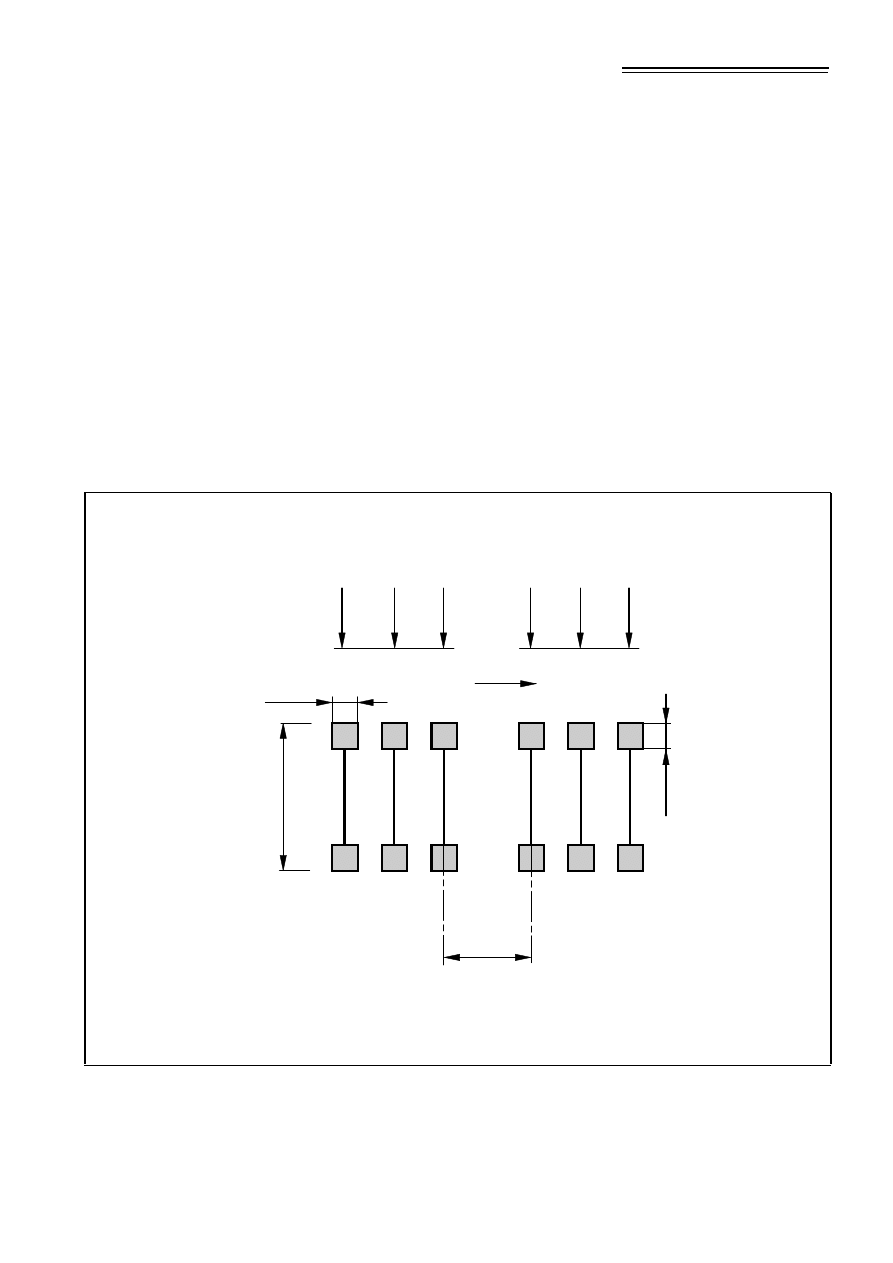
Figure NA.2
Basic longitudinal configuration of SOV model vehicles
(a) SOV-250 Vehicle
Tractor-1
Trailer Bogie-1
Trailer Bogie-2
Tractor-2
(b) SOV-350 Vehicle
Tractor-1
Trailer Bogie-1
Trailer Bogie-2
Tractor-2
1.85 m
1.35 m
1.35 m
5.0 m
165
kN
1.85 m
1.35 m
1.35 m
1.5 m - 40 m
5.0 m
100 kN
100 kN
6 axles x 225 kN @ 1.5 m
5 axles x 225 kN @ 1.5 m
165
kN
165
kN
165
kN
165
kN
165
kN
1.85 m
1.35 m
1.35 m
5.0 m
1.85 m
1.35 m
1.35 m
1.5 m - 40 m
5.0 m
100 kN
100 kN
8 axles x 225 kN @ 1.5 m
8 axles x 225 kN @ 1.5 m
165
kN
165
kN
165
kN
165
kN
165
kN
165
kN
Licensed copy: BSI USER 06 Document Controller, Midmac Contracting Co. W.L.L, Version correct as of 14/10/2010
12:11, (c) BSI
NA to BS EN 1991-2:2003
8
• © BSI 2008
The lateral wheel arrangement for the trailer axles of all the SOV model
vehicles is shown in Figure NA.3. All the wheels are of equal weight. The
contact surface of each wheel should be taken as a square of
sides 0,35 m.
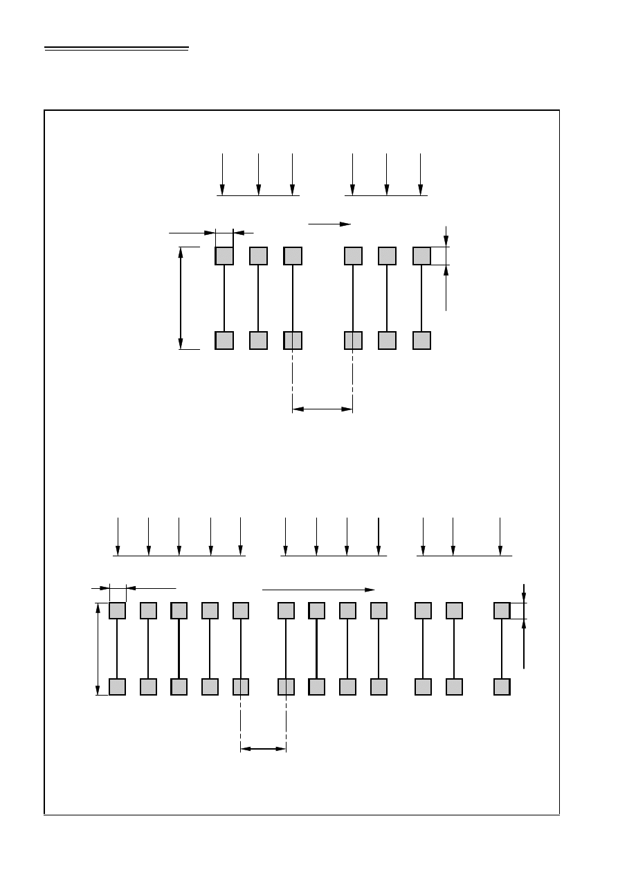
Figure NA.2
Basic longitudinal configuration of SOV model vehicles
(continued)
(c) SOV-450 Vehicle
Tractor-1
Trailer Bogie-1
Trailer Bogie-2
Tractor-2
(d) SOV-600 Vehicle
Tractor-1
Trailer Bogie-1
Trailer Bogie-2
Tractor-2
NOTE For simplicity, 6-axle trailer bogies are shown. The actual number of axles of trailer bogie should be
that stated above the figure.
1.85 m
1.35 m
1.35 m
5.0 m
1.85 m
1.35 m
1.35 m
1.5 m - 40 m
5.0 m
100 kN
100 kN
10 axles x 225 kN @ 1.5 m
10 axles x 225 kN @ 1.5 m
165
kN
165
kN
165
kN
165
kN
165
kN
165
kN
1.85 m
1.35 m
1.35 m
5.0 m
1.85 m
1.35 m
1.35 m
1.5 m - 40 m
5.0 m
100 kN
100 kN
14 axles x 225 kN @ 1.5 m
13 axles x 225 kN @ 1.5 m
165
kN
165
kN
165
kN
165
kN
165
kN
165
kN
Licensed copy: BSI USER 06 Document Controller, Midmac Contracting Co. W.L.L, Version correct as of 14/10/2010
12:11, (c) BSI
© BSI 2008 •
9
NA to BS EN 1991-2:2003
The tractor axles of the model vehicles have two wheels, each of equal
weight and with square contact areas of side 0,35 m. The outside track
and overall width of the vehicle is 3,0 m.
NA.2.16.3
Dynamic amplification factors
In determining the load effects of SV and SOV vehicles, the basic axle
loads given in Figures NA.1 and NA.2 should be multiplied by the
appropriate Dynamic Amplification Factor (DAF) for each axle as given
in Table NA.2, depending on the value of the basic axle load.
NA.2.16.4
Application of special vehicle models on the
carriageway
The SV or SOV vehicle loading should be combined with Load Model 1,
given in 4.3.2 of BS EN 1991-2, together with the load adjustment
factors given in NA.2.12 as follows.
i) Only one SV or SOV model vehicle should be considered on any
one superstructure.
ii) The Load Model 1 should be considered to be at the “frequent”
values as defined in 4.5 of BS EN 1991-2 and in BS EN 1990,
Annex A.2 and its National Annex. The loading should be applied
to each notional lane and the remaining area of the bridge deck.
Figure NA.3
Lateral wheel arrangement for trailer axles of all SOV models
Key
A = Outside track and overall vehicle width, 3,0 m
A
0.175
0.35
0.35
0.8
1.05
0.8
3.0
0.175
Table NA.2
Dynamic Amplification Factors for the SV and SOV vehicles
Basic axle load
DAF
100 kN
1,20
130 kN
1,16
165 kN
1,12
180 kN
1,10
225 kN
1,07
Licensed copy: BSI USER 06 Document Controller, Midmac Contracting Co. W.L.L, Version correct as of 14/10/2010
12:11, (c) BSI

NA to BS EN 1991-2:2003
10
• © BSI 2008
The SV or SOV vehicle can be placed at any transverse position on the
carriageway, either wholly within one notional lane or straddling two
adjacent lanes, with its side parallel to the kerb. The SV or SOV vehicle
should be placed at the most unfavourable position transversely and
longitudinally over the loaded length, in order to produce the most
severe load effect at the section being considered. The SV or SOV
vehicle should be applied on influence lines in its entirety and should not
be truncated.
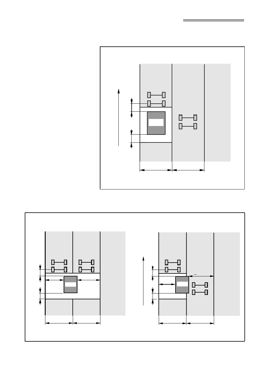
Where the SV or SOV vehicle lies fully within a notional lane the
associated Load Model 1 loading should not be applied within 5 m from
the centre of outermost axles (front and rear) of the SV or SOV vehicle
in that lane as illustrated in Figure NA.4.
Where the SV or SOV vehicle lies partially within a notional lane and the
remaining width of the lane, measured from the side of the SV or SOV
vehicle to the far edge of the notional lane, is less than 2,5 m [see
Figure NA.5(a)], the associated Load Model 1 loading should not be
applied within 5 m of the centre of the outermost axles (front and rear)
of the SV or SOV vehicle in that lane.
Where the SV or SOV vehicle lies partially within a notional lane and the
remaining width of lane, measured from the side of the SV or SOV
vehicle to the far edge of the notional lane, is greater than or equal
to 2,5 m [see Figure NA.5(b)], the “frequent” value of the uniformly
distributed load of the Load Model 1 may be applied over the remaining
width of the notional lane (in addition to remaining parts of the lane).
The “frequent” value of the tandem system for that notional lane may be
applied anywhere along its length.
On the remaining lanes not occupied by the SV or SOV vehicle, the Load
Model 1 at its “frequent” value should be applied in accordance
with 4.3.2 of BS EN 1991-2.
Licensed copy: BSI USER 06 Document Controller, Midmac Contracting Co. W.L.L, Version correct as of 14/10/2010
12:11, (c) BSI
© BSI 2008 •
11
NA to BS EN 1991-2:2003
Figure NA.4
Typical application of SV or SOV and Load Model 1 loading
when the SV or SOV vehicle lies fully within a notional lane
Key
A = Direction of travel 1 = Lane 1
2 = Lane 2
3 = Remaining area
Figure NA.5
Typical application of SV or SOV and Load Model 1 loading
when the SV or SOV vehicle straddles two adjacent lanes
(a) Distance to the far edge < 2.5 m
(b) Distance to the far edge
≥
2.5 m
Key
A = Direction of travel 1 = Lane 1 2 = Lane 2 3 = Remaining area
1
2
A
3.0 m
3.0 m
TS
TS
UDL
5 m
SV/SOV
q1
D
UDL
3
\
1,q
q
1
q2
D
\
1,q
q
2
qr
D
\
1,q
q
r
Q2
D \
1,Q
Q
2
Q1
D \
1,Q
Q
1
5 m
1
2
3.0 m
3.0 m
TS
TS
UDL
UDL
5 m
3
Q1
D \
1,Q
Q
2
Q2
D \
1,Q
Q
1
<
2.5 m
<
2.5 m
q1
D
\
1,q
q
1
q2
D
\
1,q
q
2
qr
D
\
1,q
q
r
5 m
SV/SOV
A
1
2
3.0 m
3.0 m
TS
TS
UDL
UDL
5 m
SV/SOV
q1
D
\
1,q
q
1
q2
D
\
1,q
q
2
qr
D
\
1,q
q
r
Q1
D \
1,Q
Q
1
Q2
D \
1,Q
Q
2
<
2.5 m
<
2.5 m
5 m
3
Licensed copy: BSI USER 06 Document Controller, Midmac Contracting Co. W.L.L, Version correct as of 14/10/2010
12:11, (c) BSI

NA to BS EN 1991-2:2003
12
• © BSI 2008
The notional lanes are located so as to produce the maximum load effect
at the part of the structure under consideration in accordance with 4.2.4
of BS EN 1991-2.
NA.2.17
Upper limit of the braking force on road bridges
[BS EN 1991-2:2003, 4.4.1 (2)]
The upper limit for the braking force should be taken as 900 kN.
NA.2.18
Horizontal forces associated with Load Model 3
[BS EN 1991-2:2003, 4.4.1 (3)]
NA.2.18.1
Longitudinal braking and acceleration forces
The longitudinal force should be taken as the more severe of either the
braking or the acceleration force, determined as below.
The characteristic value of longitudinal braking force on individual
axles, Q
lk,S
, expressed in kN, of special vehicles (both SV and SOV)
should be calculated as follows:
Q
lk,S
=
$
w
Where
$
is the deceleration factor and w is the basic axle load of the
relevant SV or SOV vehicle in kN shown in Figures NA.1, NA.2 and
NA.3. The value of
$
should be taken as 0,5 for SV80, 0,40 for
SV100, 0,25 for the SV196 and 0,20 for all of the SOV model vehicles.
The acceleration force should be taken as 10% of the gross weight of the
SV or SOV vehicle and distributed between the axles and wheels in the
same proportion as the vertical loads.
NA.2.18.2
Centrifugal force
The characteristic value of centrifugal force from SV or SOV vehicles,
Q
tk,S
, should be calculated as follows and applied in a manner similar to
Q
tk
for normal traffic as given in BS EN 1991-2:2003, 4.4.2.
whichever is greater: 30 or
Where:
V = velocity of the SV or SOV vehicle in m/sec
V
Limit
= speed limit on the road in m/sec
W = weight of the SV or SOV vehicle in kN
r = radius of curvature in m
g = acceleration due to gravity = 9.8 m/sec
2
ρ
= 0,86 for SV80, 0,77 for SV100, 0,55 for SV196, 0,41 for
SOV 250, 0,36 for SOV 350, 0,33 for SOV 450 and 0,30 for
SOV 600.
The centrifugal force should be distributed between axles and wheels in
the same proportion as the vertical loads.
{
ρ
=
V
}
× ×
≤
+
100
150
Limit
g r
V
r
2
,
tk S
W V
Q
g r
×
=
×
Licensed copy: BSI USER 06 Document Controller, Midmac Contracting Co. W.L.L, Version correct as of 14/10/2010
12:11, (c) BSI

© BSI 2008 •
13
NA to BS EN 1991-2:2003
NA.2.19
Horizontal force transmitted by expansion
joints or applied to structural members
[BS EN 1991-2:2003, 4.4.1 (6)]
The recommended value should be used.
NA.2.20
Lateral forces on road bridge decks
[BS EN 1991-2:2003, 4.4.2 (4)]
The minimum transverse force due to skew braking or skidding, Q
trk
,
should be taken as 50% of the longitudinal braking force, Q
lk
, for loaded
lengths up to 120 m. For loaded lengths greater than or equal to 120 m
a transverse force of 280 kN should be used.
NA.2.21
Groups of traffic loads
[BS EN 1991-2:2003, 4.5.1 Table 4.4a Notes a)
and b)]
The groups of traffic loads should be taken as defined in Table NA.3
instead of Table 4.4a of BS EN 1991-2.
Licensed copy: BSI USER 06 Document Controller, Midmac Contracting Co. W.L.L, Version correct as of 14/10/2010
12:11, (c) BSI
14
•
©
BSI
2008
NA to BS EN 1991-2:2003
Table NA.3
Assessment of groups of traffic loads (characteristic values of the multi-component action)
Load type
Carriageway
Footways and
cycletracks
Vertical forces
Horizontal forces
Vertical forces
only
Reference
4.3.2
4.3.3
Annex A
4.3.5
4.4.1
4.4.2
5.3.2.1
Equation (5.1)
Load system
LM1 (TS and
UDL)
LM2 (Single
axle)
LM3 (Special
vehicles)
LM4 (Crowd
loading)
Braking and
acceleration
forces
Centrifugal and
transverse forces
Uniformly
distributed load
Groups of loads gr1a
Characteristic
0.6 times
Characteristic
gr1b
Characteristic
gr2
Frequent
(4)
Characteristic
Characteristic
gr3
(1)
Characteristic
gr4
Characteristic
Characteristic
gr5
Frequent
(4)
Characteristic
gr6
Characteristic
Characteristic
Characteristic
Dominant component action (the group is sometimes designated by this component for convenience).
(1)
This group is irrelevant if gr4 is considered
(2)
Characteristic value obtained from 5.3.2.1
(3)
This is a reduced value accompanying the characteristic value of LM1 and should not be factored by
ψ
1
. However, when gr1a is combined with leading non-traffic actions this
value should be factored by
ψ
0
(4)
The
ψ
1
factors should be taken from the UK National Annex to BS EN 1990
Licensed copy: BSI USER 06 Document Controller, Midmac Contracting Co. W.L.L, Version correct as of 14/10/2010
12:11, (c) BSI

© BSI 2008 •
15
NA to BS EN 1991-2:2003
NA.2.22
Conditions for use of Fatigue Load Models
[BS EN 1991-2:2003, 4.6.1 (2) Note 2c]
There are no special conditions for the use of Fatigue Load Model 1.
Fatigue Load Model 2 should only be used for cases where the fatigue
verification is not influenced by the simultaneous presence of several
lorries on the bridge, unless account of their presence is taken using the
following approach:
(i) Where bridge influence line lengths permit, the maximum and
minimum stresses caused by Fatigue Load Model 2 should be
obtained by considering the worst load effect of the most onerous
vehicle accompanied in the same lane, with a 40 m clearance, by the
lightest vehicle in Table 4.6 of BS EN 1991-2, if this causes a worse
load effect.
(ii) Where two or more notional lanes influence the design detail, the
maximum and minimum stresses should be obtained from Fatigue
Load Model 2 by placing the most onerous vehicle on the most
onerous part of the influence line in the most onerous lane, plus the
lightest vehicle on the most onerous part of the influence line in one
other lane.
NA.2.23
Definition of traffic categories and traffic flows
[BS EN 1991-2:2003, 4.6.1 (3) Note 1]
Heavy goods vehicle numbers for use in fatigue design should be taken
as indicated in Table NA.4 with the additional Notes 4 and 5. Heavy
goods vehicle counts may be obtained from site surveys by doubling the
observed number of lorries with three or more axles.
Licensed copy: BSI USER 06 Document Controller, Midmac Contracting Co. W.L.L, Version correct as of 14/10/2010
12:11, (c) BSI

NA to BS EN 1991-2:2003
16
• © BSI 2008
NA.2.24
Dynamic additional amplification factor due to
expansion joints [BS EN 1991-2:2003, 4.6.1 (6)]
The recommended value should be used.
NA.2.25
Fatigue Load Model 3
[BS EN 1991-2:2003, 4.6.4 (3)]
The conditions of application for two vehicles in the same lane should
be determined for the individual project.
NA.2.26
Fatigue Load Model 4 [BS EN 1991-2:2003,
4.6.1 (2) Note 2(e), 4.6.5 (1) Note 2]
As allowed in 4.6.5(1) Note 2 and 4.6.1(2) Note 2(e), the Fatigue Load
Model 4 as defined below, along with the rules for its application, should
be used in place of the model given in 4.6.5 of BS EN 1991-2.
Fatigue Load Model 4 may be used where the application of
models 1, 2 and 3 all fail to provide sufficient fatigue life. Fatigue Load
Model 4 may also be used when the influence line length, for details
sensitive to fatigue, is short enough to have reversals of sign within a
loaded length that is similar to typical vehicle wheel and axle spacings.
Table NA.4
Indicative numbers of heavy goods vehicles expected per year
and per lane in the United Kingdom
Traffic categories
N
obs
per lane (millions per year)
Type
Carriageway
layout
No. of lanes per
carriageway
Each slow lane
Each fast lane
Motorway
Dual
3
2.0
1.5
Motorway
Dual
2
1.5
1
All purpose
Dual
3
All purpose
Dual
2
n/a
Slip road
Single
2
All purpose
Single
3
1.0
0
All purpose
Single
2
0
Slip road
Single
1
n/a
All purpose
Single
2
0.5
0
Local (low lorry flow)
Single
2
0.05
0
NOTE 1 Notes 1 and 2 in BS EN 1991-2 may be disregarded for UK purposes.
NOTE 2 There is no general relation between traffic categories for fatigue verifications, and the loading classes
and associated
α
factors mentioned in
4.2.2 and 4.3.2.
NOTE 3 Intermediate values of N
obs
are not excluded, but are unlikely to have significant effect on the fatigue
life.
NOTE 4 Basing the numbers of heavy goods vehicles on counts of multi-axled lorries ensures a reasonably
reliable match between the codified traffic model and the number and types of vehicle that cause the most fatigue
damage in the actual traffic.
NOTE 5 The values presented in Table NA.4 are design values that are intended to reflect approximate road
capacities, and they may not match observations of current usage. Traffic flows at a small number of sites may
exceed these values, but the differences are unlikely to have a very significant influence on designs.
Licensed copy: BSI USER 06 Document Controller, Midmac Contracting Co. W.L.L, Version correct as of 14/10/2010
12:11, (c) BSI

© BSI 2008 •
17
NA to BS EN 1991-2:2003
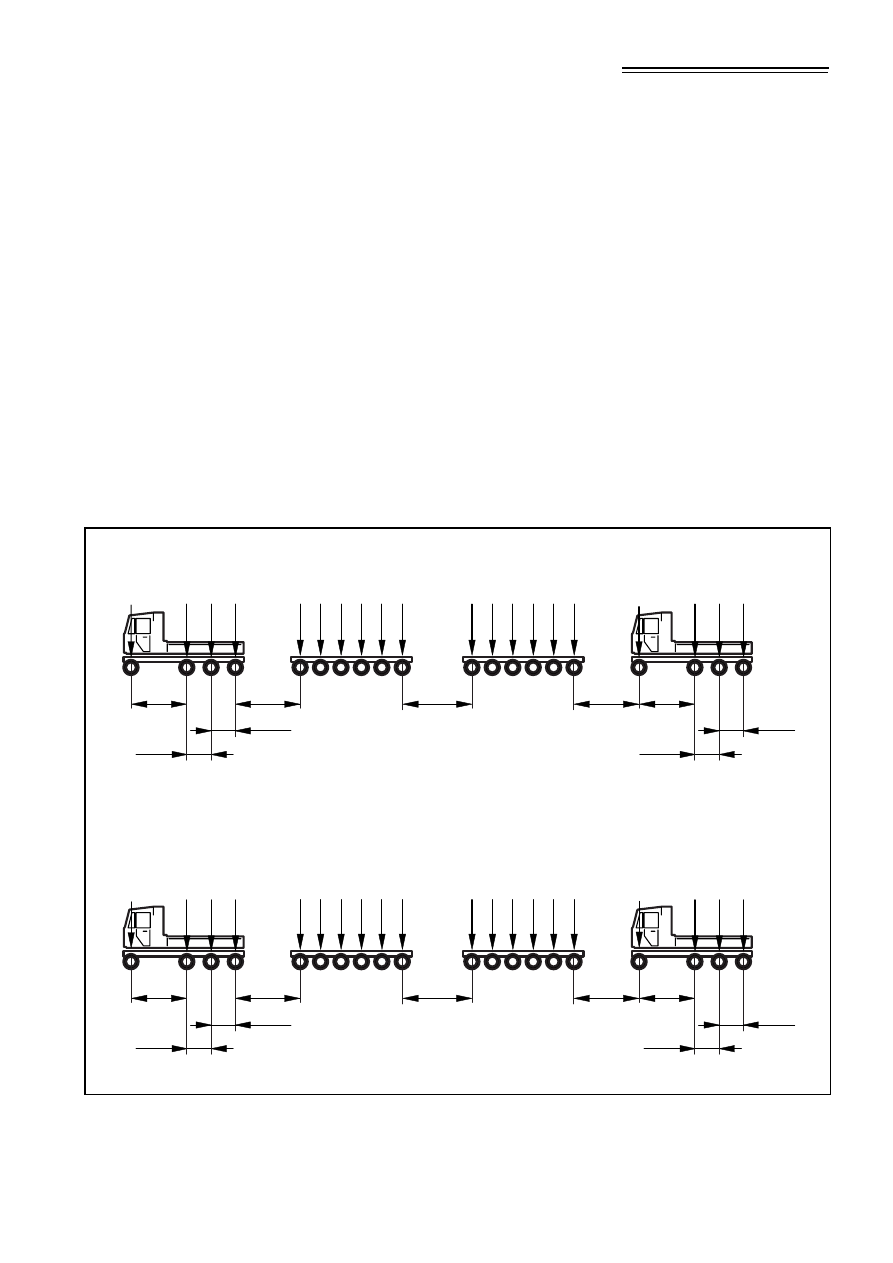
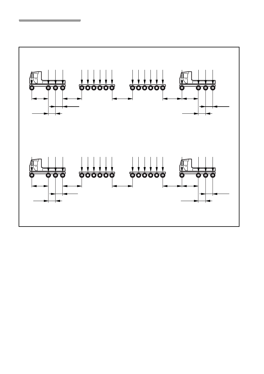
The standard lorries given in Table NA.5 for Fatigue Load Model 4
should be used for fatigue design on all routes in the UK. Where the
length of the influence line permits, and/or where two or more notional
lanes influence the design detail, Fatigue Load Model 4 should be
applied as follows.
The fatigue damaging stress cycles due to the transit of Fatigue Load
Model 4 lorries should be assessed and counted using the rainflow
counting procedure described in BS EN 1993-1-9. Fatigue damage
should be assessed on the basis of stress cycles calculated from two
traffic lanes only. These lanes (described as lanes 1 and 2 for the
purpose of this clause) are the two notional lanes that individually cause
the most theoretical fatigue damage in the component under
consideration. Vehicle numbers in these lanes should be obtained from
Table NA.4.
Damage summation D
d
is obtained by adding contributions from the
following cases.
i) Lane 1 traffic alone, with 80% of lane 1 lorry numbers.
ii) 20% of lane 1 traffic running in convoy with vehicles at 40 m
spacing, centre of rearmost axle of front vehicle to centre of
foremost axle of vehicle behind.
iii) Lane 2 traffic alone, with 80% of lane 2 lorry numbers.
iv) 20% of lane 2 traffic running in convoy with vehicles at 40 m
spacing, centre of rearmost axle of front vehicle to centre of
foremost axle of vehicle behind.
The effect of side-by-side running should be allowed for by multiplying
the total damage, D
d,
by factor K
b
.Z, where: K
b
= ratio of the maximum
stress range caused by single vehicles in lane 2 to the maximum stress
range caused by single vehicles in lane 1, and:
i) if loaded length
≤
3,0 m, Z = 1,0;
ii) if 3,0 m < loaded length < 20 m, Z varies linearly in proportion
to the logarithm of the loaded length from 1,0 to 1,5;
iii) if loaded length
≥
20 m, Z=1,5.
Licensed copy: BSI USER 06 Document Controller, Midmac Contracting Co. W.L.L, Version correct as of 14/10/2010
12:11, (c) BSI
18
•
©
BSI
2008
NA to BS EN 1991-2:2003
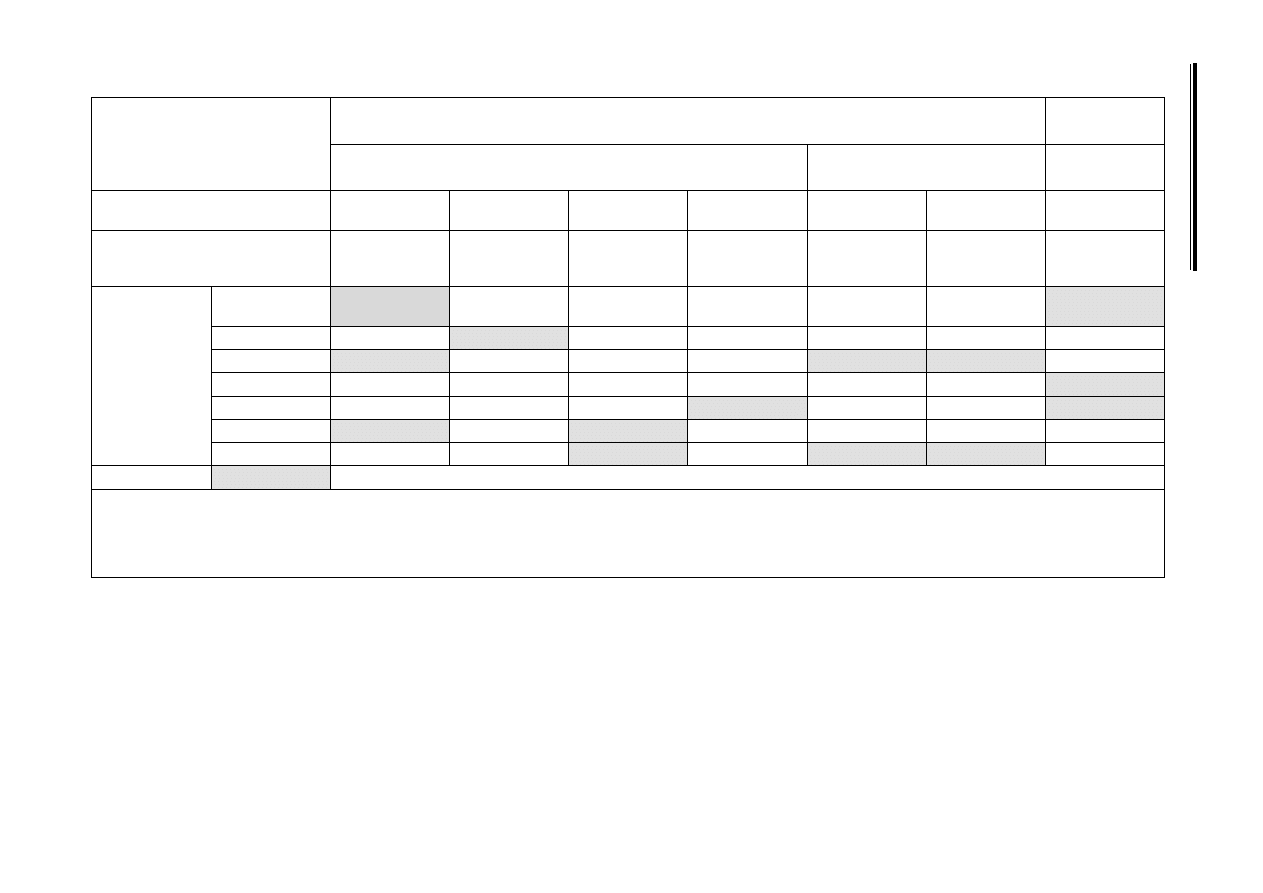
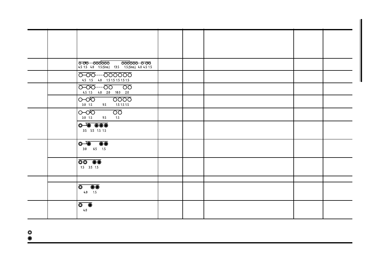
Table NA.5
Set of equivalent lorries for Fatigue Load Model 4
Total
axles
Chassis type Average spacings, m
Loading
group
Total
weight
kN
Axle loads, kN
No in each
group per
million
commercial
vehicles
Vehicle
Designation
18
Girder trailer
and 2 tractors
H
3680
80 160 160 240(6no.) 240(6no.) 80 160 160
10
18GT-H
M
1520
80 160 160 60(6no.) 60(6no.) 80 160 160
30
18GT-M
9
Girder trailer
and tractor
H
1610
70 140 140 210 210 210 210 210 210
20
9TT-H
M
750
50 110 110 80 80 80 80 80 80
40
9TT-M
7
Girder trailer
and tractor
H
1310
70 140 140 240 240 240 240
30
7GT-H
M
680
60 130 130 90 90 90 90
70
7GT-M
Articulated
H
790
70 100 100 130 130 130 130
20
7A-H
5
Articulated
H2
630
70 130 130 150 150
280
5A-H2
H
380
70 100 70 70 70
90 500
5A-H
M
300
50 70 60 60 60
90 000
5A-M
L
190
40 60 30 30 30
90 000
5A-L
4
Articulated
H
240
40 80 60 60
45 000
4A-H
M
175
40 55 40 40
45 000
4A-M
L
145
35 50 30 30
45 000
4A-L
Rigid
H
280
50 50 90 90
8 000
4R-H
M
240
40 40 80 80
8 000
4R-M
L
120
20 20 40 40
8 000
4R-L
3
Articulated
Not used
3A
Rigid
H
240
60 90 90
10 000
3R-H
M
195
45 75 75
10 000
3R-M
L
120
60 45 45
10 000
3R-L
2
Rigid
H
135
50 85
170 000
2R-H
M
65
30 35
170 000
2R-M
L
30
15 15
200 000
2R-L
Key
O = Special axle. Applies to all vehicles over 5 axles with 2–8 tyres and outer track 2,4 m to 3,4 m. Specific vehicle axle arrangements are to be defined for the individual project.
= Steering axle. 2 tyre, 2,0 m track
= Standard axle. 4 tyre, 1,8 m track
Licensed copy: BSI USER 06 Document Controller, Midmac Contracting Co. W.L.L, Version correct as of 14/10/2010
12:11, (c) BSI

© BSI 2008 •
19
NA to BS EN 1991-2:2003
NA.2.27
Fatigue Load Model 5 (based on recorded traffic
data) [BS EN 1991-2:2003, 4.6.6 (1)]
The derivation of a site-specific model should be considered as follows:
i) where knowledge of local traffic conditions is poor;
ii) where local circumstances are very particular (e.g. sea ports).
The fatigue damaging stress cycles due to transit of recorded lorries
should be assessed and counted using the rainflow counting procedure
described in BS EN 1993-1-9. Fatigue damage should be assessed on
the basis of stress cycles calculated from two traffic lanes only. These
lanes (described as lanes 1 and 2) are the two traffic lanes that
individually cause the most theoretical fatigue damage in the
component under consideration.
The stress cycles obtained from analysis of recorded traffic data should
be multiplied by a Dynamic Amplification Factor :
fat
which can be taken
as :
fat
= 1.2 for a pavement surface of “good” roughness and :
fat
= 1.4
for a pavement of “medium” roughness. An additional Dynamic
Amplification Factor should be applied for locations close to expansion
joints as given in 4.6.1(6) (See also Annex B of BS EN 1991-2).
The procedure for damage summation D
d
should be as that given in
NA.2.26 for Fatigue Load Model 4.
NA.2.28
Collision forces on piers and other supporting
members [BS EN 1991-2:2003, 4.7.2.1 (1)]
For the application of this clause, refer to BS EN 1991-1-7 and its
National Annex.
NA.2.29
Collision forces on decks
[BS EN 1991-2:2003, 4.7.2.2 (1) Note 1]
For the application of this clause, refer to BS EN 1991-1-7 and its
National Annex.
NA.2.30
Effects of collision forces on vehicle restraint
systems [BS EN 1991-2:2003, 4.7.3.3]
NA.2.30.1
[BS EN 1991-2:2003, 4.7.3.3 (1) Note 1]
The appropriate class of forces given in Table NA.6 should be selected
in place of Table 4.9(n) of BS EN 1991-2, depending on specific
applications.
Licensed copy: BSI USER 06 Document Controller, Midmac Contracting Co. W.L.L, Version correct as of 14/10/2010
12:11, (c) BSI

NA to BS EN 1991-2:2003
20
• © BSI 2008
The forces in Table NA.6 should be applied uniformly over a length
of 3 m at the top of the traffic face of the vehicle restraint system and in
a position along the line of the vehicle restraint system that produces
the maximum effects on the part of the structure under consideration.
NA.2.30.2
[BS EN 1991-2:2003, 4.7.3.3 (1) Note 3]
The vertical forces acting simultaneously with the collision forces
should be taken as 0,75 times the loading given by Load Model 1
in 4.3.2 of BS EN 1991-2 and the full accidental wheel/vehicle loading
given in 4.7.3.1 of BS EN 1991-2. The three sets of forces should be
applied in a way that will have the most severe effect on the part of the
structure under consideration.
NA.2.30.3
[BS EN 1991-2:2003, 4.7.3.3 (2) Note]
The recommended value should be used.
NA.2.31
Collision forces on structural members
[BS EN 1991-2:2003, 4.7.3.4(1)]
Structural members above or beside the carriageway level should be
provided with protective measures e.g. barriers. If not, the following
options should be considered.
i) Design for vehicle collision forces; see BS EN 1991-2, 4.7.2.1
and NA.2.28.
ii) Design for nominal vehicle collision forces for the provision of
minimum robustness and for the situation where damage or
failure to the structural member will not cause collapse of the
structure; see BS EN 1991-2, 4.7.3.4 (2). These nominal vehicle
collision forces should be determined for the individual project.
Strategies for accidental design situations are set out in
BS EN 1991-1-7 and its NA.
Table NA.6
Forces due to collision with vehicle restraint systems for
determining global effects
Class
Transverse force
(kN)
Longitudinal force
(kN)
Vertical force
(kN)
Examples of applications
A
100
—
—
Normal containment flexible
parapets (e.g. metal post and rail
parapets)
B
200
—
—
Normal containment rigid
parapets (e.g. reinforced
concrete parapets)
C
400
100
175
Very high containment flexible
parapets (e.g. metal post and rail
parapets)
D
600
100
175
Very high containment rigid
parapets (e.g. reinforced
concrete parapets)
Licensed copy: BSI USER 06 Document Controller, Midmac Contracting Co. W.L.L, Version correct as of 14/10/2010
12:11, (c) BSI

© BSI 2008 •
21
NA to BS EN 1991-2:2003
NA.2.32
Actions on pedestrian parapets
[BS EN 1991-2:2003, 4.8 (1) Note 2]
The required class of pedestrian parapet for the particular situation
should be chosen in accordance with EN 1317-6 and determined for the
individual project. The characteristic value of forces transferred to the
structure should be taken as the design loads given in EN 1317-6 for the
relevant class of pedestrian parapet.
For the design of the supporting structure the minimum horizontal load
should be taken as 1,6 kN/m, corresponding to Class E, for normal
situations, and 3.0 kN/m
2
, corresponding to Class J, for exceptional
situations where crowding can occur. The horizontal load should be
applied at the top of the pedestrian parapet and should be considered to
act simultaneously with the uniformly distributed vertical loads defined
in 5.3.2.1 of BS EN 1991-2.
NA.2.33
Supporting structures to pedestrian parapets,
which are not adequately protected against
vehicle collisions [BS EN 1991-2:2003, 4.8 (3)]
The recommended value should be used.
NA.2.34
Model for vertical loads on backfill behind
abutments and wing walls adjacent to bridges
[BS EN 1991-2:2003, 4.9.1 (1) Note 1]
NA.2.34.1
General
For determining the vertical and horizontal pressures in the backfill
behind an abutment or wing wall, the carriageway located behind the
abutments is loaded with the vehicle loads as described in NA.2.34.2
and NA.2.34.3. These vehicle loads should be considered as
characteristic loads.
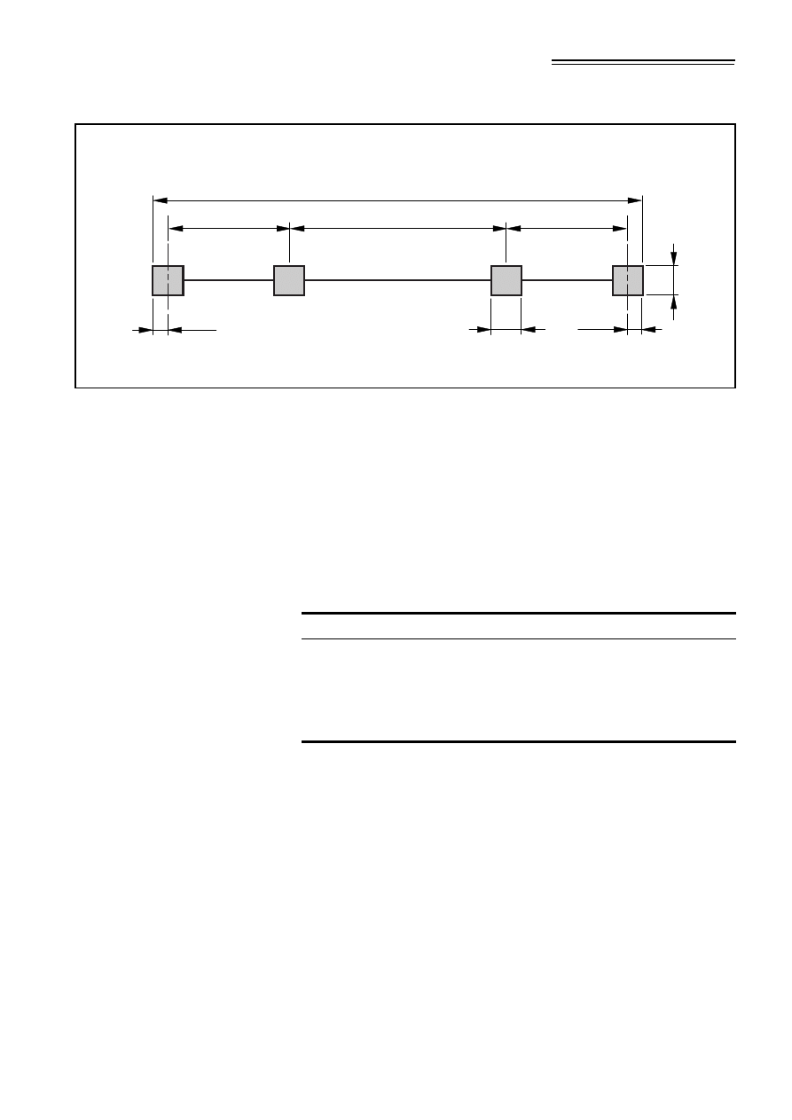
NA.2.34.2
Loading from normal traffic
The model vehicle with the configuration given in Figure NA.6 should
be used. Each axle consists of two wheels of equal weight at a distance
apart of 2,0 m to the centre line of each wheel. The contact surface of
each wheel should be taken as a square of sides 0,40 m.
Licensed copy: BSI USER 06 Document Controller, Midmac Contracting Co. W.L.L, Version correct as of 14/10/2010
12:11, (c) BSI
NA to BS EN 1991-2:2003
22
• © BSI 2008
All the axle loads given in Figure NA.6 should be multiplied by an
Overload Factor of 1,5 and a Dynamic Amplification Factor of 1,4. The
effect of the Dynamic Amplification Factor on vertical and horizontal
earth pressure may be considered to reduce linearly from 1,4 at surface
level to 1,0 at a depth of 7,0 m. Where appropriate, detailed modelling
may be used to determine more accurately the variation of Dynamic
Amplification Factor with depth. Vehicles should be positioned in a
maximum of three adjacent notional lanes. The axle loads for the vehicle
in the third lane should be factored by a lane factor of 0,5.
The maximum load effect from the following two cases should be used
for design.
i) A single vehicle in each notional lane.
ii) Convoy of vehicles in each notional lane with the Dynamic
Amplification Factor set to 1,0 (represents a traffic jam
situation).
The vehicles within each lane should be positioned, laterally and
longitudinally, to maximize the load effects at the part of the structure
under consideration. However, a minimum lateral spacing of 1.0 m is
maintained between the centrelines of wheels from two adjacent
vehicles. In the case of a convoy of vehicles a minimum longitudinal
spacing of 3.0 m should be kept between the last axle of the leading
vehicle and the first axle of the trailing vehicle.
Where the load model behind the abutment is applied in conjunction
with either Load Model 1 or Load Model 2 on the deck, the two load
models should be applied simultaneously, without modification to their
rules of application.
Figure NA.6
Vehicle model for abutments and wing walls
Key
1 = Direction of travel
2.0 m
65
kN
65
kN
115
kN
75
kN
3.9 m
1.3 m
1.2 m
0.40 m
0.40 m
1
Licensed copy: BSI USER 06 Document Controller, Midmac Contracting Co. W.L.L, Version correct as of 14/10/2010
12:11, (c) BSI

© BSI 2008 •
23
NA to BS EN 1991-2:2003
The load model should be considered to form part of gr1a and gr1b, in
which it should be applied at its characteristic value, and gr2, in which it
should be applied at its frequent value (see Table NA.3). Combination
factors for the load model should be taken equal to those for the tandem
axle system of Load Model 1.
NA.2.34.3
Loading from special vehicles
The abutments and wing walls adjacent to bridges should be designed
for the effects of special vehicles (both SV and SOV models) where
required.
The special vehicles for Load Model 3, given in NA.2.16, along with the
rules of its application, should be used for this purpose. For the
evaluation of vertical and horizontal pressures, due to vehicle loading
behind the abutment, only one SV or SOV vehicle model, appropriate to
the road class, and in one notional lane, should be considered. The
vehicle load model given in NA.2.34.2 may be applied in two adjacent
lanes but with all the axle loads multiplied by a factor of 0,75.
The effect of the Dynamic Amplification Factor on vertical and
horizontal earth pressure may be considered to reduce linearly from the
values given in Table NA.2 at the surface to 1,0 at a depth of 7,0 m.
Where appropriate, detailed modelling may be used to determine more
accurately the variation of the Dynamic Amplification Factor with
depth.
NA.2.35
Load models for inspection gangways
[BS EN 1991-2:2003, 5.2.3 (2)]
The recommended model in BS EN 1991-2 should be used.
NA.2.36
Uniformly distributed load
[BS EN 1991-2:2003, 5.3.2.1 (1)]
Where the risk of a continuous dense crowd exists (e.g. footbridges
serving a sports stadium) the Load Model 4 defined in 4.3.5 of
BS EN 1991-2, corresponding to q
fk
= 5,0 kN/m
2
should be used. In
other cases, the uniformly distributed load, q
fk
, should be taken as
follows.
Where L is the loaded length in m.
NA.2.37
Concentrated load
[BS EN 1991-2:2003, 5.3.2.2 (1)]
The characteristic value of the concentrated load Q
fwk
given in
BS EN 1991-2 should be used.
q
fk
2 0
,
120
L
10
+
------------------- kN m
⁄
2
+
=
2,5 kN m
2
q
fk
5,0 kN m
2
⁄
≤
≤
⁄
Licensed copy: BSI USER 06 Document Controller, Midmac Contracting Co. W.L.L, Version correct as of 14/10/2010
12:11, (c) BSI

NA to BS EN 1991-2:2003
24
• © BSI 2008
NA.2.38
Service vehicle [BS EN 1991-2:2003, 5.3.2.3 (1)
Note 1]
Where footbridges do not have permanent provisions to prevent the
entry of vehicles on to the footbridge, the vehicle model given in
Figure 5.2 of BS EN 1991-2 with characteristic axle loads,
Q
sv1
= 115 kN and Q
sv2
= 65 kN should be used.
NA.2.39
Horizontal force on footbridges
[BS EN 1991-2:2003, 5.4 (2)]
The recommended values should be used.
NA.2.40
General actions for accidental design situations
for footbridges [BS EN 1991-2:2003, 5.6.1 (1)]
No additional information is provided.
NA.2.41
Collision forces on piers of footbridges
[BS EN 1991-2:2003, 5.6.2.1 (1)]
For application, refer to BS EN 1991-1-7 and its National Annex.
NA.2.42
Collision forces on decks of footbridges
[BS EN 1991-2:2003, 5.6.2.2 (1)]
For application, refer to BS EN 1991-1-7 and its National Annex.
NA.2.43
Accidental presence of a heavy vehicle
[BS EN 1991-2:2003, 5.6.3 (2)]
The characteristics of a vehicle, which may be accidentally present on
the footbridge where no permanent obstacle is provided, is defined
in NA.2.38. Alternative load model characteristics may be determined
for the individual project.
NA.2.44
Dynamic models for pedestrian actions on
footbridges [BS EN 1991-2:2003, 5.7 (3)]
NA.2.44.1
General
Dynamic models for pedestrian loads and associated comfort criteria
are given below. Two distinct analyses are required:
a) the determination of the maximum vertical deck acceleration and
its comparison with the comfort criteria (as described in
NA.2.44.3 to NA.2.44.6), and
b) an analysis to determine the likelihood of large synchronized
lateral responses (as described in NA.2.44.7).
For unusual bridges, or in circumstances where other responses or
response mechanisms are likely to cause discomfort (for example the
wind buffeting of pedestrian bridges over railways), the effects of
actions other than those described should be considered.
Licensed copy: BSI USER 06 Document Controller, Midmac Contracting Co. W.L.L, Version correct as of 14/10/2010
12:11, (c) BSI

© BSI 2008 •
25
NA to BS EN 1991-2:2003
The following activities are not included and any associated
requirements should be determined for the individual project:
•
mass gathering (for example marathons, demonstrations);
•
deliberate pedestrian synchronization;
•
vandal loading.
NA.2.44.2
Dynamic actions to be considered
(1) All bridges should be categorized into bridge classes by their usage
to determine the appropriate actions due to pedestrians. Group
sizes for each bridge class should be applied as given in
Table NA.7.
(2) Crowd loading densities to be used in design should be determined
for the individual project and be appropriate for the intended
bridge usage. Table NA.7 provides recommended values of crowd
densities for each bridge class.
(3) Depending on the expected bridge usage, it may be determined
that jogging cases given in Table NA.7 can be neglected for
individual projects.
NA.2.44.3
Vertical response calculations
(1) It should be demonstrated that the peak vertical deck accelerations
determined for the actions described in NA.2.44.4 and NA.2.44.5
are less than the limits defined in NA.2.44.6.
(2) In calculating the peak vertical deck accelerations account should
be taken of the following.
•
The load models provided should be applied in order to
determine the maximum vertical acceleration at the most
unfavourable location on the footbridge deck.
•
The calculated vertical responses should include the effect of
torsional or other motions.
•
Modes other than the fundamental mode may need to be taken
into account in order to calculate the maximum responses.
Table NA.7
Recommended crowd densities for design
Bridge class
Bridge usage
Group size
(walking)
Group size
(jogging)
Crowd density
ρ
(persons/m
2
)
(walking)
A
Rural locations seldom used and in sparsely
populated areas.
N = 2
N = 0
0
B
Suburban location likely to experience slight
variations in pedestrian loading intensity on an
occasional basis.
N = 4
N = 1
0.4
C
Urban routes subject to significant variation in
daily usage (e.g. structures serving access to
offices or schools).
N = 8
N = 2
0.8
D
Primary access to major public assembly
facilities such as sports stadia or major public
transportation facilities.
N = 16
N = 4
1.5
Licensed copy: BSI USER 06 Document Controller, Midmac Contracting Co. W.L.L, Version correct as of 14/10/2010
12:11, (c) BSI

NA to BS EN 1991-2:2003
26
• © BSI 2008
•
When the vertical deck modes are not well separated,
consideration should be given to the use of more sophisticated
methods of analysis, in order to determine combined mode
responses. In all cases, it is conservative to use the vector sum
of the peak accelerations for those modes that need such
combination.
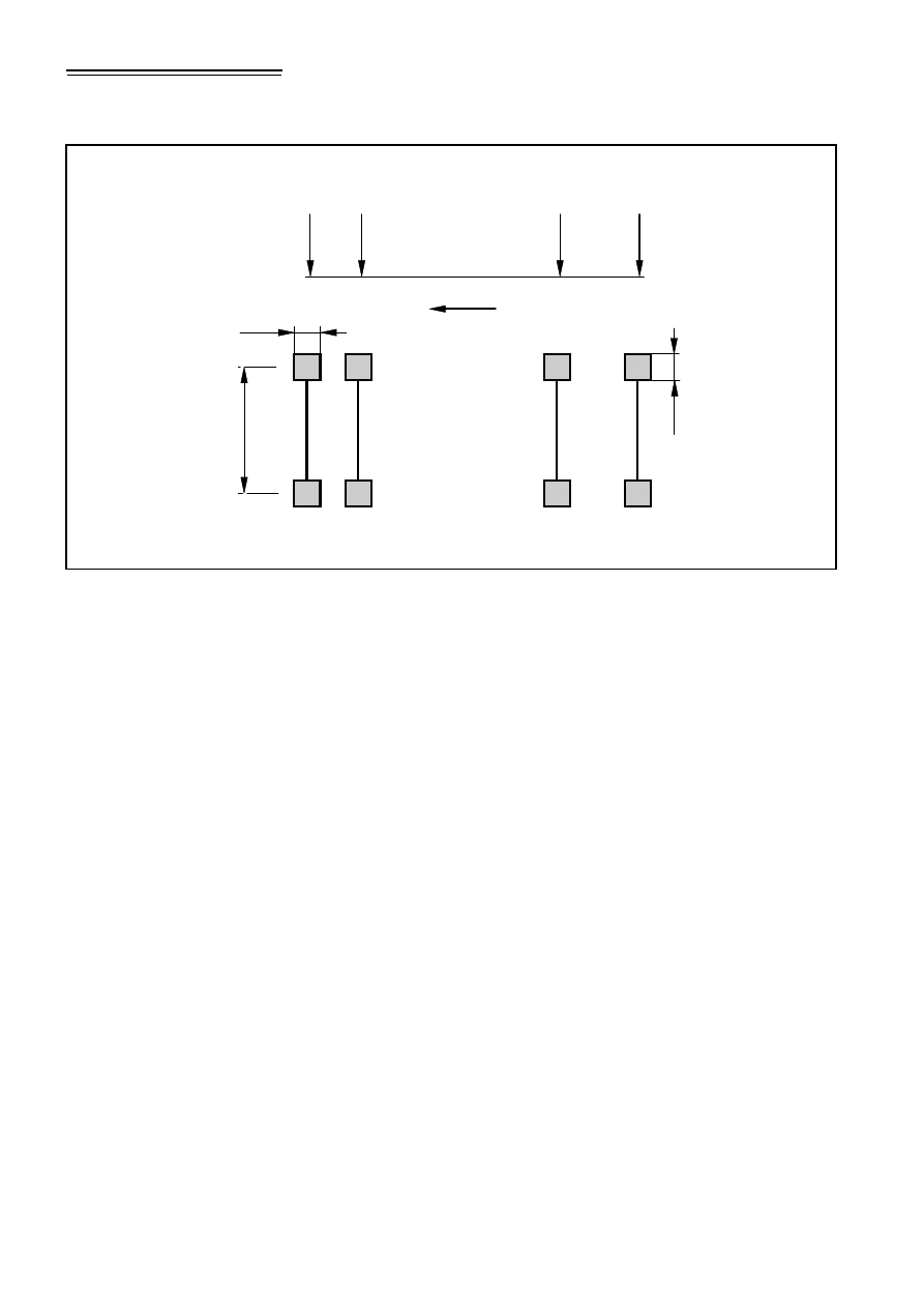
NA.2.44.4
Dynamic actions representing the passage of single
pedestrians and pedestrian groups
(1) The design maximum vertical accelerations that result from single
pedestrians or pedestrian groups should be calculated by assuming
that these are represented by the application of a vertical pulsating
force F (N), moving across the span of the bridge at a constant
speed v
t
, as follows:
Where:
N
is the number of pedestrians in the group obtained from
NA.2.44.2.
F
0
is the reference amplitude of the applied fluctuating force
(N) given in Table NA.8 (and represents the maximum
amplitude of the applied pedestrian force at the most likely
pace frequency).
f
v
is the natural frequency (Hz) of the vertical mode under
consideration.
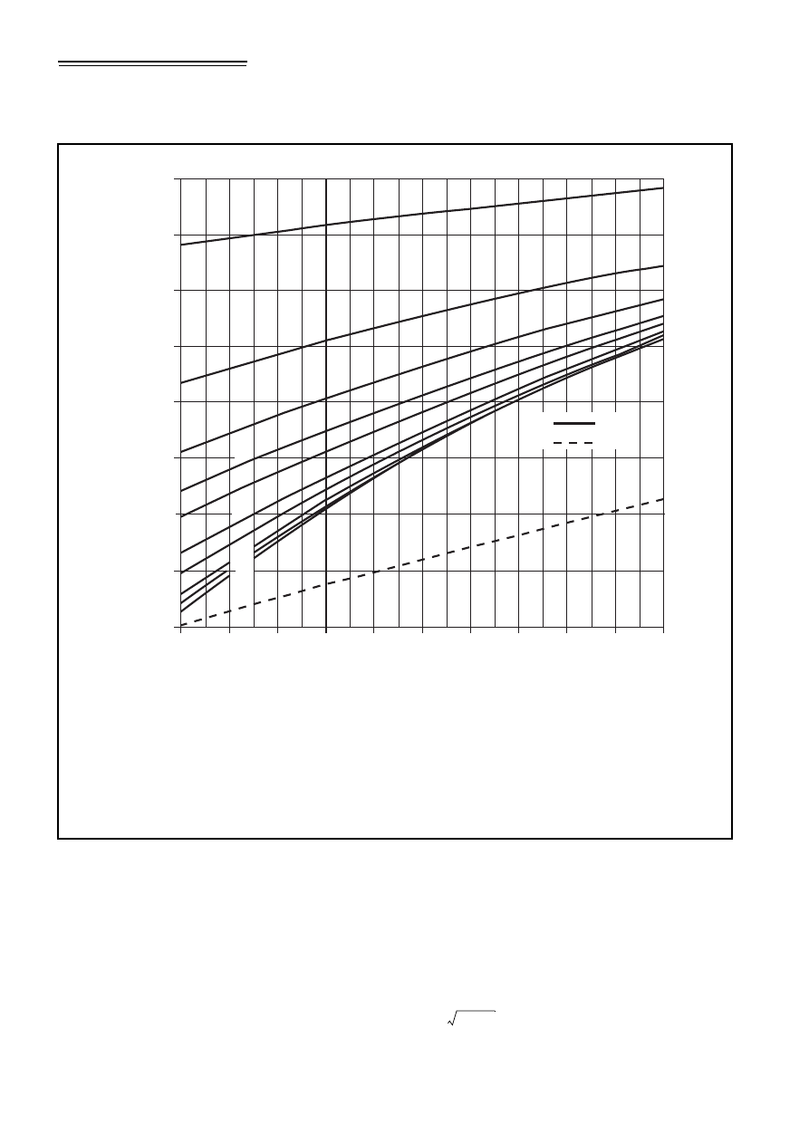
k(f
v
) given in Figure NA.8, is a combined factor to deal with (a)
the effects of a more realistic pedestrian population, (b)
harmonic responses and (c) relative weighting of pedestrian
sensitivity to response.
t
elapsed time (seconds).
γ
is a reduction factor to allow for the unsynchronized
combination of actions in a pedestrian group, is a function
of damping and effective span, and is obtained from
Figure NA.9.
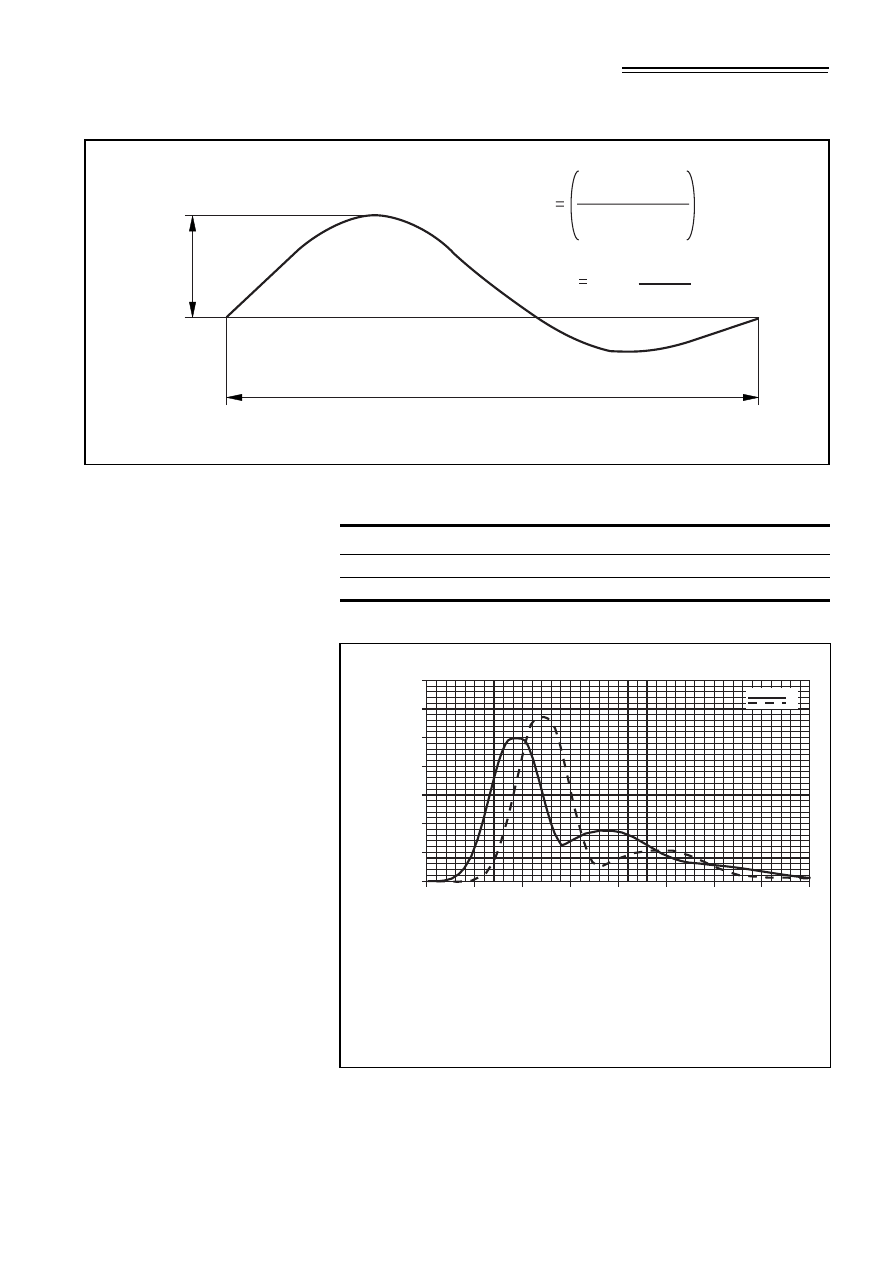
S
eff
is an effective span length (m) equal to the area enclosed by
the vertical component of the mode shape of interest divided
by 0.634 times the maximum of the vertical component of
the same mode shape (see Figure NA.7).
(In all cases it is conservative to use S
eff
= S).
S
is the span of the bridge (m).
F
F
0
.k f
v
( )
. 1
γ
. N 1
–
(
)
.
+
2
π
.f
v
.t
(
)
sin
=
Licensed copy: BSI USER 06 Document Controller, Midmac Contracting Co. W.L.L, Version correct as of 14/10/2010
12:11, (c) BSI
© BSI 2008 •
27
NA to BS EN 1991-2:2003
Figure NA.7
Effective span calculation
Key
1 = Area B 2 = Area A
Table NA.8
Parameters to be used in the calculation of pedestrian response
Load parameters
Walking
Jogging
Reference load, F
0
(N)
280
910
Pedestrian crossing speed, v
t
(m/sec)
1,7
3
Figure NA.8
Relationships between k(f
v
) and mode frequencies f
v
Key
A = Walking
B = Jogging/running
1 = Mode frequency f
v
(Hz)
2 = Combined population and harmonic factor k(fv)
J
max
1
2
S
O
0.634
S
eff
S
S
eff
Area A + Area B
0.634.
J
max
1.4
1.2
1
0.8
0.6
0.4
0.2
0
0
1
2
3
4
5
6
7
8
1
2
A
B
Licensed copy: BSI USER 06 Document Controller, Midmac Contracting Co. W.L.L, Version correct as of 14/10/2010
12:11, (c) BSI
NA to BS EN 1991-2:2003
28
• © BSI 2008
NA.2.44.5
Steady state modelling of pedestrians in crowded
conditions
(1) The design maximum vertical accelerations that result from
pedestrians in crowded conditions may be calculated by assuming
that these are represented by a vertical pulsating distributed load
w (N/m
2
), applied to the deck for a sufficient time so that steady
state conditions are achieved as follows:
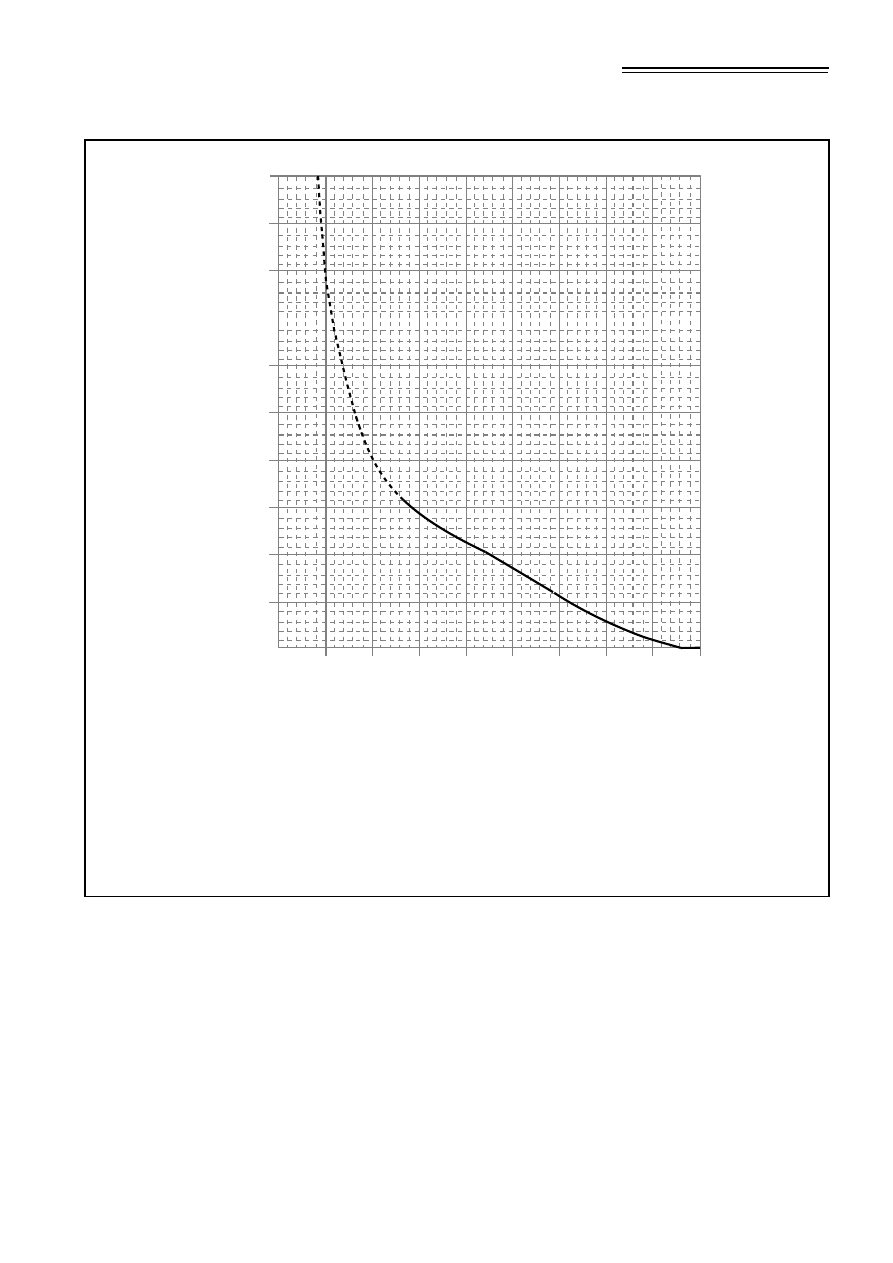
Figure NA.9
Reduction factor, *, to allow for the unsynchronized
combination of pedestrian actions within groups and crowds
Key
1 = Pedestrian groups
2 = Crowd loading
A = Structural damping – logarithmic decrement,
$
B = Reduction factor on effective number of pedestrians,
*
NOTE All curves represent the variation of the reduction factor with structural damping for the value of
effective span, S
eff
(m), given
0.8
0.3
0.4
0.6
0.1
0.5
0.2
0
0.7
0.08
0.04
0.14
0.06
0.16
0.1
0.02
0
0.12
0.18
0.20
A
B
10
15
20
12
30
40
60
100
200
300
1
2
w
1.8
F
0
A
------
⎝ ⎠
⎛ ⎞ .k f
v
( )
.
γ
.N
λ
⁄
.
2
π
.f
v
.t
(
)
sin
=
Licensed copy: BSI USER 06 Document Controller, Midmac Contracting Co. W.L.L, Version correct as of 14/10/2010
12:11, (c) BSI

© BSI 2008 •
29
NA to BS EN 1991-2:2003
Where:
N
is the total number of pedestrians distributed over the span
S.
N =
ρ
A =
ρ
S b
ρ
is the required crowd density obtained from NA.2.44.2 but
with a maximum value of 1.0 persons/m
2
. (This is because
crowd densities greater than this value produce less vertical
response as the forward motion slows.)
S
is the span of the bridge (m)
b
is the width of the bridge subject to pedestrian loading
γ
is a factor to allow for the unsynchronized combination of
actions in a crowd and is obtained from Figure NA.9.
λ
is a factor that reduces the effective number of pedestrians
when loading from only part of the span contributes to the
mode of interest.
λ
= 0.634(S
eff
/ S).
For other symbols see NA.2.44.4 (1).
(2) In order to obtain the most unfavourable effect this loading should
be applied over all relevant areas of the footbridge deck with the
direction of the force varied to match the direction of the vertical
displacements of the mode for which responses are being
calculated.
(3) Understanding of the dynamic response of structures in crowded
conditions is still evolving and there is evidence to suggest that the
peak acceleration arising from the application of w as specified in
NA.2.44.5 (1) may be conservative in some cases. Alternatively
appropriate dynamic models may be determined for the individual
project.
NA.2.44.6
Recommended serviceability limits for use in design
(1) The maximum vertical acceleration calculated from the above
actions should be less than the design acceleration limit given by:
a
limit
= 1.0 k
1
k
2
k
3
k
4
m/s
2
and 0.5 m/s
2
≤
a
limit
≤
2,0 m/s
2
Where:
k
1
, k
2
and k
3
are the response modifiers taken from Tables NA.9
to NA.11 in which:
k
1
= site usage factor
k
2
= route redundancy factor
k
3
= height of structure factor.
k
4
is an exposure factor which is to be taken as 1.0 unless
determined otherwise for the individual project. See also
NA.2.44.6 (2).
Licensed copy: BSI USER 06 Document Controller, Midmac Contracting Co. W.L.L, Version correct as of 14/10/2010
12:11, (c) BSI

NA to BS EN 1991-2:2003
30
• © BSI 2008
Values of k
1
, k
2
and k
3
other than those given in Tables NA.9 to NA.11
may be determined for the individual project using Figure NA.10 as a
guide.
Table NA.9
Recommended values for the site usage factor k
1
Bridge function
k
1
Primary route for hospitals or other high sensitivity routes
0,6
Primary route for school
0.8
Primary routes for sports stadia or other high usage routes
0.8
Major urban centres
1,0
Suburban crossings
1,3
Rural environments
1,6
Table NA.10
Recommended values for the route redundancy factor k
2
Route redundancy
k
2
Sole means of access
0,7
Primary route
1,0
Alternative routes readily available
1,3
Table NA.11
Recommended values for the structure height factor k
3
Bridge height
k
3
Greater than 8 m
0,7
4 m to 8 m
1,0
Less than 4 m
1,1
Licensed copy: BSI USER 06 Document Controller, Midmac Contracting Co. W.L.L, Version correct as of 14/10/2010
12:11, (c) BSI

© BSI 2008 •
31
NA to BS EN 1991-2:2003
(2) k
4
may be assigned a value of between 0.8 and 1.2 to reflect other
conditions that may affect the users’ perception towards vibration.
These may include consideration of parapet design (such as
height, solidity or opacity), quality of the walking surface (such as
solidity or opacity) and provision of other comfort-enhancing
features. The value to be taken should be determined for the
individual project.
(3) For some types of bridges (for example bridges in remote
locations), less onerous design limits may be applied, where a
suitable risk assessment has been carried out. Any relaxation of
the design limits should be determined for the individual project.
NA.2.44.7
The avoidance of unstable lateral responses due to
crowd loading
(1) Structures should be designed to avoid unintended unstable lateral
responses.
(2) If there are no significant lateral modes with frequencies
below 1.5 Hz it may be assumed that unstable lateral responses
will not occur.
(3) For all other situations, it should be demonstrated that unstable
lateral responses due to crowd loading will not occur, using the
following method.
Figure NA.10
Response modifiers
Key
1 = Response modifier, k
i
Primary
route for
hospital
Primary
route
for school
Major
urban
centres
Suburban
crossings
Site usage
factor k
1
Route
redundancy
factor k
2
Height of
structure
factor k
3
Rural
environments
Sole means of access
Primary
route
Alternative routes
readily available without
additional hazard to user
Greater than 8 m
4-8 m
Less
than
4 m
1
2
1.5
1
0.5
0
Licensed copy: BSI USER 06 Document Controller, Midmac Contracting Co. W.L.L, Version correct as of 14/10/2010
12:11, (c) BSI

NA to BS EN 1991-2:2003
32
• © BSI 2008
For all deck modes of vibration having a significant lateral
horizontal component and a frequency below 1.5 Hz, compare the
pedestrian mass damping parameter, D, and the mode frequency
with the stability boundary defined in Figure NA.11. If the
pedestrian mass damping parameter falls below the indicated
boundary divergent lateral responses may be expected. Values
above the line should be stable.
The pedestrian mass damping parameter D is given by:
is the mass per unit length of the bridge
is the mass per unit length of pedestrians for the
relevant crowd density obtained from NA.2.44.2
assuming that each pedestrian weighs 70 kg
is the structural damping when expressed as a
damping ratio,
δ
logarithmic decrement of decay of vibration between
successive peaks
D
m
bridge
.
ξ
m
pedestrian
--------------------------------
=
m
bridge
m
pedestrian
ξ
ξ
δ
2
π
(
)
⁄
=
Licensed copy: BSI USER 06 Document Controller, Midmac Contracting Co. W.L.L, Version correct as of 14/10/2010
12:11, (c) BSI
© BSI 2008 •
33
NA to BS EN 1991-2:2003
NA.2.45
Alternative load models for railway bridges
[BS EN 1991-2:2003, 6.1 (2)]
Alternative load models for non-public footpaths and actions due to
traction and braking should be as set out in the following.
NA.2.45.1
Actions for non-public footpaths
The values recommended in 6.3.7 of BS EN 1991-2 should be used
except as follows.
6.3.7 (2) In addition, where the walkway supports a cable route, an
allowance of 1 kN/m or the actual weight of the cables, whichever is
greater.
Figure NA.11
Lateral lock-in stability boundaries
Key
A = Frequency of lateral mode (Hz)
B = Pedestrian mass damping parameter, D
C = Unstable
D = Stable
NOTE Reliable test measurements are only available for footbridge lateral frequencies in the range
of 0.5 to 1.1 Hz. The extensions to the stability curve beyond this region are based upon a theoretical model
of response only and should be used with caution.
A
B
0.4
0.2
1.4
1.2
0.6
0.8
1
0
1.8
1.6
2
0
0.2
0.4
0.6
0.8
1
1.2
1.4
1.6
1.8
D
C
Licensed copy: BSI USER 06 Document Controller, Midmac Contracting Co. W.L.L, Version correct as of 14/10/2010
12:11, (c) BSI

NA to BS EN 1991-2:2003
34
• © BSI 2008
6.3.7 (3) For the design of local elements a concentrated load
Q
k
= 2,0 kN applied to a circular area of 100 mm diameter, or a
concentrated load of 1 kN, whichever has the more severe effect.
6.3.7 (4) Horizontal handrail loading of 0.74 kN/m or a horizontal force
of 0.5 kN applied at any point to the top rail, whichever has the more
severe effect.
NA.2.45.2
Actions due to traction and braking
Actions due to traction and braking should be taken as the greater of
equations 6.20 and 6.21, or the following.
i) Provision should be made for the nominal loads due to traction
and application of brakes as given in Table NA.12. These loads
are considered as acting at rail level in a direction parallel to the
tracks. No addition for dynamic effects should be made to the
longitudinal loads calculated as specified in this subclause.
ii) For bridges supporting ballasted track, up to one-third of the
longitudinal loads may be assumed to be resisted by track
outside the bridge structure, provided that no expansion
switches or similar rail discontinuities are located on, or
within, 18 m of either end of the bridge.
iii) Structures and elements carrying single tracks should be
designed to carry the larger of the two loads produced by
traction and braking in either direction parallel to the track.
iv) Where a structure or an element carries two tracks, both tracks
are considered as being occupied simultaneously. Where the
tracks carry traffic in opposite directions, the load due to
braking should be applied to one track and the load due to
traction to the other. Structures and elements carrying two
tracks in the same direction should be subjected to braking or
traction on both tracks, whichever gives the greater effect.
Consideration should be given to braking and traction, acting in
opposite directions, producing rotational effects.
v) Where elements carry more than two tracks, longitudinal loads
should be considered as applied simultaneously to two tracks
only.
Table NA.12
Nominal longitudinal loads
Standard loading
type
Load arising
from
Loaded length
(m)
Longitudinal
load
(kN)
Load Model 71,
SW/0 and HSLM
Traction (30% of
load on driving
wheels)
up to 3
150
from 3 to 5
225
from 5 to 7
300
from 7 to 25
24 (L – 7) + 300
over 25
750
Braking (25% of
load on braked
wheels)
up to 3
125
from 3 to 5
187
from 5 to 7
250
over 7
20 (L – 7) + 250
Licensed copy: BSI USER 06 Document Controller, Midmac Contracting Co. W.L.L, Version correct as of 14/10/2010
12:11, (c) BSI

© BSI 2008 •
35
NA to BS EN 1991-2:2003
NA.2.46
Other types of railways
[BS EN 1991-2:2003, 6.1 (3)P]
The loading and characteristic values of actions should be determined
for the individual project (for example for light rail systems and
underground railways).
NA.2.47
Temporary bridges [BS EN 1991-2:2003, 6.1 (7)]
The requirements for temporary railway bridges should be determined
for the individual project.
NA.2.48
Values of
α
factor
[BS EN 1991-2:2003, 6.3.2 (3)P]
The value of
α
should be taken as 1.1.
Alternative values of
α
may be determined for the individual project.
NA.2.49
Choice of lines for heavy rail traffic
[BS EN 1991-2:2003, 6.3.3 (4)P]
Generally there is no requirement to design for SW/2 loading in the UK.
Alternative requirements for heavy rail traffic may be determined for the
individual project.
NA.2.50
Alternative requirements for a dynamic analysis
[BS EN 1991-2:2003, 6.4.4 (1)]
The requirements for determining whether a dynamic analysis is
required (in addition to static analysis) are shown in Figures NA.12
and NA.13. Figure NA.12 is only applicable to simple structures that
exhibit only longitudinal line beam behaviour. Figure NA.13 is
applicable to both simple and complex structures.
NOTE 1 When determining whether a dynamic analysis is required it is
essential to differentiate between simple and complex structures, i.e. those
which exhibit only longitudinal line beam behaviour and may be
represented by line beams, and those that exhibit longitudinal/transverse
behaviour which require more complex representation/modelling.
NOTE 2 Simple structures which exhibit longitudinal line beam
behaviour with insignificant contributions from other dynamic modes will
generally comprise of deck type structures of slab, beam and slab or box
and slab construction where the tracks are located over the webs of
longitudinal spanning elements and where the deck/floor elements are not
required to directly distribute axle/wheel load effects to the longitudinal
elements by transverse bending.
NOTE 3 Complex structures require deck/floor elements to distribute
axle/wheel loads to primary longitudinal elements. Complex structures
will typically include through/half through structures with primary
transverse spanning deck/floors, as well as deck type structures of beam
and slab (or box and slab) construction where the deck/floor elements are
required to distribute loads to the longitudinal elements in bending.
Licensed copy: BSI USER 06 Document Controller, Midmac Contracting Co. W.L.L, Version correct as of 14/10/2010
12:11, (c) BSI
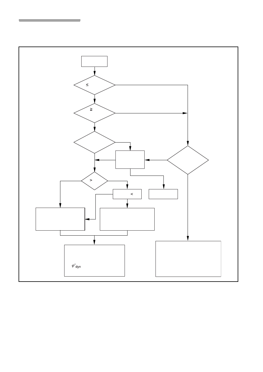
NA to BS EN 1991-2:2003
36
• © BSI 2008
Figure NA.12
Flow chart for determining whether a dynamic analysis is
necessary for “simple” structures
Start
V 200 km/h
L 40 m
(see Note 1)
within limits
of Figure
NA.14
Y
N
Y
N
N
N
N
Y
Y
Y
Y
n
0
within limits
of Figure
NA.14
n
0
n
0
n
T
Accepted
by relevant
authority
Accepted
1.2
Is Skew 15
Redesign
For the dynamic analysis
use the eigenforms for
torsion and for bending
For the dynamic analysis
may use the eigenforms for
bending only
Not
accepted
Dynamic analysis required.
Calculate bridge deck
acceleration and
etc, and undertake
fatigue check
Dynamic analysis not required.
Acceleration check and fatigue
check at resonance not required.
Use in accordance with
EN 1991-2 6.4.5
(see Notes 4 and 5)
Licensed copy: BSI USER 06 Document Controller, Midmac Contracting Co. W.L.L, Version correct as of 14/10/2010
12:11, (c) BSI

© BSI 2008 •
37
NA to BS EN 1991-2:2003
Where:
V
is the maximum line speed at the site (km/h)
L
is the span length (m)
n
0
is the first natural bending frequency of the bridge loaded by
permanent actions (Hz)
n
T
is the first natural torsional frequency of the bridge loaded by
permanent actions (Hz)
NOTE 1 Simply supported structure only with negligible skew and rigid
supports.
NOTE 2 For bridges with a first natural frequency within the limits given
by Figure NA.9 and a maximum line speed at the site V
line
not
exceeding 200 km/h a dynamic analysis is not required.
NOTE 3
ϕ
½
dyn
is the dynamic impact increment for Real Trains or Load
Model HSLM for the structure given in
6.4.6.5 (3).
NOTE 4 A dynamic analysis is required where the Frequent Operating
speed of a Real Train equals a Resonant Speed of the structure [see
BS EN 1991-2
6.4.6.6 (2)].
NOTE 5 Valid providing the bridge meets the requirements for resistance,
deformation limits given in Annex A2 to BS EN 1990,
A2.4.4 and the
maximum coach body acceleration (or associated deflection limits)
corresponding to a very good standard of passenger comfort given in
Annex A2 to BS EN 1990,
A2.4.4.3.
NOTE 6 This figure is only applicable to structures which may be
represented by line beams
Licensed copy: BSI USER 06 Document Controller, Midmac Contracting Co. W.L.L, Version correct as of 14/10/2010
12:11, (c) BSI
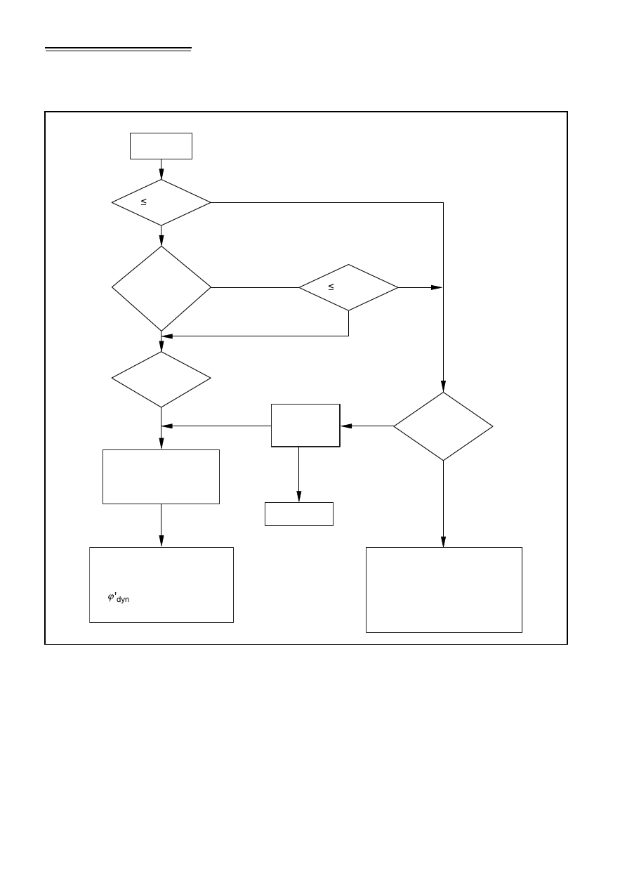
NA to BS EN 1991-2:2003
38
• © BSI 2008
Figure NA.13
Flow chart for determining whether a dynamic analysis is
required for “simple” and “complex” structures
Start
V 180 km/h
within limits
of Figure
NA.14
Y
N
N
N
Y
Y
Y
n
0
within limits
of Figure
NA.14
n
0
Accepted
by relevant
authority
Accepted
Redesign
For the dynamic analysis
use the eigenforms for
torsion and for bending
Not
accepted
Dynamic analysis not required.
Acceleration check and fatigue
check at resonance not required.
Use in accordance with
EN 1991-2 6.4.5
(see Notes 4 and 5)
Dynamic analysis required.
Calculate bridge deck
acceleration and
etc, and undertake
fatigue check
Complex
structure
with metal desk
(see Note 1)
N
V 180 km/h
Y
Licensed copy: BSI USER 06 Document Controller, Midmac Contracting Co. W.L.L, Version correct as of 14/10/2010
12:11, (c) BSI

© BSI 2008 •
39
NA to BS EN 1991-2:2003
Where:
V
is the maximum line speed at the site (km/h)
L
is the span length (m)
n
0
is the first natural bending frequency of the bridge loaded by
permanent actions (Hz)
n
T
is the first natural torsional frequency of the bridge loaded by
permanent actions (Hz)
NOTE 1 Metallic floors with closely spaced transverse ‘T’ ribs (e.g. as
utilized in “Western Region Box Girder Structures”) may be assumed to
have an adequate dynamic response for speeds up to 200 km/h when
designed with the following characteristics: a minimum deck plate
thickness of 30 mm, maximum spacing of transverse ‘T’ ribs not greater
than 610 mm and satisfying minimum fatigue design requirements
of 18-27 million tonnes of heavy traffic per annum.
NOTE 2 For bridges with a first natural frequency within the limits given
by Figure NA.14 and a Maximum Line speed at the Site V
line
not
exceeding 200 km/h a dynamic analysis is not required.
NOTE 3
ϕ
½
dyn
is the dynamic impact increment for Real Trains or Load
Model HSLM for the structure given in
6.4.6.5 (3).
NOTE 4 A dynamic analysis is required where the Frequent Operating
Speed of a Real Train equals a Resonant Speed of the structure [see
BS EN 1991-2,
6.4.6.6(2)].
NOTE 5 Valid providing the bridge meets the requirements for resistance,
deformation limits given in Annex A2 to BS EN 1990,
A2.4.4, and the
maximum coach body acceleration (or associated deflection limits)
corresponding to a very good standard of passenger comfort given in
Annex A2 to BS EN 1990,
A2.4.4.3.
Licensed copy: BSI USER 06 Document Controller, Midmac Contracting Co. W.L.L, Version correct as of 14/10/2010
12:11, (c) BSI
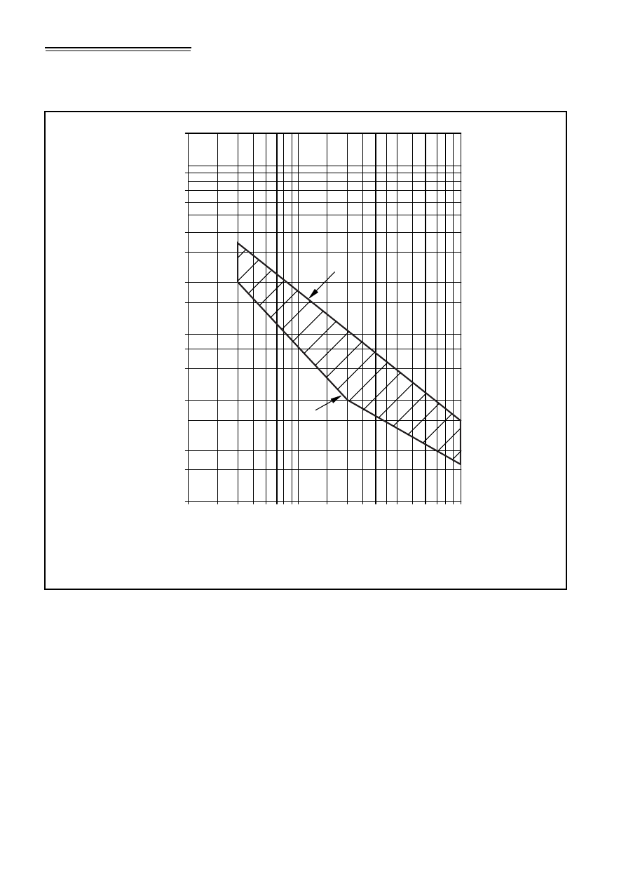
NA to BS EN 1991-2:2003
40
• © BSI 2008
Where:
n
0
is the first natural vertical mode bending frequency of the unloaded
bridge [i.e. permanent (including removable) loads only]
L is the span length for simply supported bridges or L
9
for other
bridge types.
The upper limits of n
0
is governed by the limits of application of the
allowances for the dynamic increments due to track irregularities and is
given by:
n
0 =
94.76
×
L
p0.748
The lower limit of n
0
is governed by dynamic impact criteria and is given
by:
n
0
= 80/L for 4 m
≤
L
≤
20 m
n
0
= 23.58
×
L
p0.592
for 20 m
≤
L
≤
100 m.
Figure NA.14
Limits of bridge natural frequency n
0
in Hz as a function of
L in m
Key
1 = Upper limit of natural frequency
2 = Lower limit of natural frequency
1
n
0
1,0
1,5
2
4
6
8
10
15
20
40
60
80
100
150
2
4
6
8 10
15
20
40
60
80 100
2
(Hz)
L (m)
Licensed copy: BSI USER 06 Document Controller, Midmac Contracting Co. W.L.L, Version correct as of 14/10/2010
12:11, (c) BSI

© BSI 2008 •
41
NA to BS EN 1991-2:2003
NA.2.51
Choice of dynamic factor
[BS EN 1991-2:2003, 6.4.5.2 (3)P]
Generally
Φ
3
should be used.
Alternative values may be determined for the individual project.
NA.2.52
Alternative values of determinant length
[BS EN 1991-2:2003, 6.4.5.3 (1) Table 6.2]
The values of determinant length given in Table 6.2 should be used with
the following modifications.
Case 1.1 – Deck plate (for both directions) – the lesser of three times
cross girder spacing or cross girder spacing + 3 m.
Case 2.1 – Deck plate (for both directions) – cross girder
spacing + 3 m.
Case 5.7 – Longitudinal cantilevers.
NA.2.53
Determinant length of transverse cantilevers
[BS EN 1991-2:2003, 6.4.5.3, Note a, Table 6.2]
The loading to be used for establishing the determinant length of
transverse cantilevers should be determined for the individual project.
NA.2.54
Additional requirements for the application of
HSLM
[BS EN 1991-2:2003, 6.4.6.1.1 (6), Table 6.4]
Additional requirements for the application of HSLM-A and HSLM-B
may be determined for the individual project.
NA.2.55
Loading and methodology for dynamic analysis
[BS EN 1991-2:2003, 6.4.6.1.1 (7)]
The loading and methodology for the analysis should be determined for
the individual project.
NA.2.56
Additional load cases depending upon number
of tracks [BS EN 1991-2:2003, 6.4.6.1.2 (3),
Table 6.5, Note a)]
The loading should be determined for the individual project.
NA.2.57
Values of damping
[BS EN 1991-2:2003, 6.4.6.3.1 (3) Table 6.6]
Alternative values for damping should be determined for the individual
project.
Licensed copy: BSI USER 06 Document Controller, Midmac Contracting Co. W.L.L, Version correct as of 14/10/2010
12:11, (c) BSI

NA to BS EN 1991-2:2003
42
• © BSI 2008
NA.2.58
Alternative density values of materials
[BS EN 1991-2:2003, 6.4.6.3.2 (3)]
Alternative density values may be determined for the individual project.
NA.2.59
Enhanced Young’s modulus
[BS EN 1991-2:2003, 6.4.6.3.3 (3) Note 1]
Alternative Young’s modulus values may be determined for the
individual project.
NA.2.60
Other material properties
[BS EN 1991-2:2003, 6.4.6.3.3 (3) Note 2]
Other material properties may be determined for the individual project.
NA.2.61
Reduction of peak response at resonance taking
account of additional damping due to
vehicle/bridge interaction
[BS EN 1991-2:2003, 6.4.6.4 (4)]
The method should be determined for the individual project.
NA.2.62
Allowance for track defects and vehicle
imperfections [BS EN 1991-2:2003, 6.4.6.4 (5)]
Generally (1 +
ϕ
″
) should be used for line speeds less than 160 km/h
and (1 +
ϕ
″
/2) should be used for line speeds of 160 km/h and above.
Alternative requirements may be determined for the individual project.
NA.2.63
Increased height of centre of gravity for
centrifugal forces
[BS EN 1991-2:2003, 6.5.1 (2)]
Generally centrifugal forces should be taken to act outwards in a
horizontal direction at a height of 1,80 m above the running surface.
Alternative values may be determined for the individual project.
NA.2.64
Actions due to braking for loaded lengths
greater than 300 m
[BS EN 1991-2:2003, 6.5.3 (5)]
Additional requirements may be determined for the individual project.
NA.2.65
Alternative requirements for the application of
traction and braking forces
[BS EN 1991-2:2003, 6.5.3 (9)]
The requirements of 6.5.3 (9) apply.
Licensed copy: BSI USER 06 Document Controller, Midmac Contracting Co. W.L.L, Version correct as of 14/10/2010
12:11, (c) BSI

© BSI 2008 •
43
NA to BS EN 1991-2:2003
NA.2.66
Combined response of structure and track,
requirements for non-ballasted track
[BS EN 1991-2:2003, 6.5.4.1 (5)]
The requirements for non-ballasted track should be determined for the
individual project.
NA.2.67
Alternative requirements for temperature range
[BS EN 1991-2:2003, 6.5.4.3 (2) Notes 1 and 2]
The requirements of 6.5.4.3 (2) apply.
NA.2.68
Longitudinal shear resistance between track
and bridge deck
[BS EN 1991-2:2003, 6.5.4.4 (2) Note 1]
The values should be determined for the individual project.
NA.2.69
Alternative design criteria
[BS EN 1991-2:2003, 6.5.4.5]
Alternative requirements may be determined for the individual project.
NA.2.70
Minimum value of track radius
[BS EN 1991-2:2003, 6.5.4.5.1 (2)]
Alternative requirements should be determined for the specific project.
NA.2.71
Alternative calculation methods
[BS EN 1991-2:2003, 6.5.4.6]
Alternative calculation methods may be determined for the individual
project.
NA.2.72
Alternative criteria for simplified calculation
methods
[BS EN 1991-2:2003, 6.5.4.6.1 (1)]
Alternative criteria may be determined for the individual project.
NA.2.73
Longitudinal plastic shear resistance between
track and bridge deck
[BS EN 1991-2:2003, 6.5.4.6.1 (4)]
Alternative values of k may be determined for the individual project.
NA.2.74
Aerodynamic actions, alternative values
[BS EN 1991-2:2003, 6.6.1 (3)]
The aerodynamic actions due to static pressure changes as a train
passes a structure should be determined for the individual project.
Licensed copy: BSI USER 06 Document Controller, Midmac Contracting Co. W.L.L, Version correct as of 14/10/2010
12:11, (c) BSI

NA to BS EN 1991-2:2003
44
• © BSI 2008
NA.2.75
Derailment of rail traffic, additional
requirements [BS EN 1991-2:2003, 6.7.1 (2)P]
Alternative loading requirements for the design of railway structures to
resist derailment actions from rail traffic, are appropriate for the design
of all deck plates and similar local elements. These elements should be
designed to support a concentrated load of !
×
1.4
×
250 kN (where !
has a minimum value of 1,0) applied anywhere on the deck plate or local
element. No dynamic factor needs to be applied to this design load.
NA.2.76
Derailment of rail traffic, measures for
structural elements situated above the level of
the rails and requirements to retain a derailed
train on the structure
[BS EN 1991-2:2003, 6.7.1 (8)P Note 1]
Measures to mitigate the consequences of a derailment may be
determined for the individual project.
NA.2.77
Other actions
[BS EN 1991-2:2003, 6.7.3 (1)P Note]
The requirements for other actions, including for any accidental design
situation, may be determined for the individual project.
NA.2.78
Number of tracks loaded when checking
drainage and structural clearances
[BS EN 1991-2:2003, 6.8.1 (11)P Table 6.10]
Structural clearance requirements should be checked with rail traffic
actions corresponding to the number of tracks loaded in accordance
with the requirements for the number of tracks to be loaded in
Table 6.10 for “Traffic Safety Checks: Vertical deformation of the deck”.
Deformation due to railway traffic may be neglected when checking
drainage requirements.
NA.2.79
Assessment of groups of loads
[BS EN 1991-2:2003, 6.8.2 (2)]
The factors given in Table 6.11 should be used.
Where economy is not adversely affected, the recommended factors
may be increased to 1.0 to simplify the design process.
NA.2.80
Frequent values of multi-component actions
[BS EN 1991-2:2003, 6.8.3.1 (1)]
The factors given in Table 6.11 should be used.
Where economy is not adversely affected, the recommended factors
may be increased to 1.0 to simplify the design process.
Licensed copy: BSI USER 06 Document Controller, Midmac Contracting Co. W.L.L, Version correct as of 14/10/2010
12:11, (c) BSI

© BSI 2008 •
45
NA to BS EN 1991-2:2003
NA.2.81
Quasi-permanent values of multi-component
actions [BS EN 1991-2:2003, 6.8.3.2 (1)]
The value given in 6.8.3.2 (1) should be used.
NA.2.82
Fatigue load models, structural life
[BS EN 1991-2:2003, 6.9 (6)]
The design working life should be taken as 120 years.
NA.2.83
Fatigue load models, specific traffic
[BS EN 1991-2:2003, 6.9 (7)]
A special traffic mix may be determined for the individual project.
NA.2.84
Dynamic factor
[BS EN 1991-2:2003, Annex C (3)P]
Generally C.1 should be used for line speeds less than 160 km/h and C.2
should be used for line speeds of 160 km/h and above.
Alternative requirements may be specified for the individual project and
agreed with the relevant authority.
NA.2.85
Method of dynamic analysis
[BS EN 1991-2:2003, Annex C (3)P]
The method to be used should be determined for the individual project.
NA.2.86
Partial safety factor for fatigue loading
[BS EN 1991-2:2003, Annex D2 (2)]
The recommended value of
*
Ff
= 1,00 should be used.
NA.3 Decision on the status of informative
annexes
NA.3.1
Load Model 3: Models of special vehicles
[BS EN 1991-2:2003, Annex A]
Load Model 3 should not be used. The models for special vehicles
should be those given in NA.2.16.
NA.3.2
Fatigue life assessment for road bridges:
Assessment method based on recorded traffic
[BS EN 1991-2:2003, Annex B]
The Annex B may be used in conjunction with the requirements of
NA.2.27 for Fatigue Load Model 5.
Licensed copy: BSI USER 06 Document Controller, Midmac Contracting Co. W.L.L, Version correct as of 14/10/2010
12:11, (c) BSI

NA to BS EN 1991-2:2003
46
• © BSI 2008
NA.3.3
Limits of validity of Load Model HSLM
[BS EN 1991-2:2003, Annex E]
E1 May be used.
E2 Should not be used unless suitability of the methodology is
determined for the individual project.
NOTE The methodology is not suitable for many UK structural
configurations.
NA.3.4
Criteria to be satisfied if a dynamic analysis is
not required [BS EN 1991-2:2003, Annex F]
Should not be used.
NOTE The loading used to derive the criteria in Annex F has been
superseded by requirements in the HS INS TSI relating to load model
HSLM. Additionally the methodology is not suitable for most UK structural
configurations.
NA.3.5
Combined responses
[BS EN 1991-2:2003, Annex G]
May be used.
NA.3.6
Load Models for rail traffic loads
[BS EN 1991-2:2003, Annex H]
May be used.
NA.4 References to non-contradictory
complementary information
The following is a list of references that contain non-contradictory
complementary information for use with BS EN 1991-2:2003.
BS EN 1317-2, Road restraint systems – Part 2: Performance
classes, impact test acceptance criteria and test methods for safety
barriers
PD 6688-2, Guidance for the design of structures to BS EN 1991-2
TD 19 (DMRB 2.2.8) Requirements for Road Restraint Systems,
Highways Agency Design Manual for Roads and Bridges
Licensed copy: BSI USER 06 Document Controller, Midmac Contracting Co. W.L.L, Version correct as of 14/10/2010
12:11, (c) BSI

© BSI 2008 •
47
NA to BS EN 1991-2:2003
Bibliography
Standards publication
For dated references, only the edition cited applies. For undated
references, the latest edition of the referenced document (including any
amendments) applies.
BS EN 1991-1-7, Eurocode 1: Actions on structures – Part 1-7:
General actions – Accidental actions
PD 6688-2, Guidance for the design of structures to BS EN 1991-2
Other publications
prEN 1317-6, Road Restraint Systems – Part 6: Pedestrian restraint
systems. Pedestrian parapet
TD 19 (DMRB 2.2.8) Requirements for Road Restraint Systems.
Highways Agency Design Manual for Roads and Bridges
UIC 777-2R, Structures built over railway lines – Construction
requirements in the track zone
Licensed copy: BSI USER 06 Document Controller, Midmac Contracting Co. W.L.L, Version correct as of 14/10/2010
12:11, (c) BSI

BSI – British Standards Institution
BSI is the independent national body responsible for preparing British Standards.
It presents the UK view on standards in Europe and at the international level.
It is incorporated by Royal Charter.
Revisions
British Standards are updated by amendment or revision. Users of British Standards
should make sure that they possess the latest amendments or editions.
It is the constant aim of BSI to improve the quality of our products and services.
We would be grateful if anyone finding an inaccuracy or ambiguity while using this
British Standard would inform the Secretary of the technical committee responsible,
the identity of which can be found on the inside front cover.
Tel: +44 (0)20 8996 9000. Fax: +44 (0)20 8996 7400.
BSI offers members an individual updating service called PLUS which ensures that
subscribers automatically receive the latest editions of standards.
Buying standards
Orders for all BSI, international and foreign standards publications should be
addressed to Customer Services. Tel: +44 (0)20 8996 9001.
Fax: +44 (0)20 8996 7001. Email: orders@bsi-global.com. Standards are also
available from the BSI website at http://www.bsi-global.com.
In response to orders for international standards, it is BSI policy to supply the BSI
implementation of those that have been published as British Standards, unless
otherwise requested.
Information on standards
BSI provides a wide range of information on national, European and international
standards through its Library and its Technical Help to Exporters Service. Various
BSI electronic information services are also available which give details on all its
products and services. Contact the Information Centre. Tel: +44 (0)20 8996 7111.
Fax: +44 (0)20 8996 7048. Email: info@bsi-global.com.
Subscribing members of BSI are kept up to date with standards developments and
receive substantial discounts on the purchase price of standards. For details of these
and other benefits contact Membership Administration. Tel: +44 (0)20 8996 7002.
Fax: +44 (0)20 8996 7001. Email: membership@bsi-global.com.
Information regarding online access to British Standards via British Standards
Online can be found at http://www.bsi-global.com/bsonline.
Further information about BSI is available on the BSI website at
http://www.bsi-global.com.
Copyright
Copyright subsists in all BSI publications. BSI also holds the copyright, in the UK, of
the publications of the international standardization bodies. Except as permitted
under the Copyright, Designs and Patents Act 1988 no extract may be reproduced,
stored in a retrieval system or transmitted in any form or by any means – electronic,
photocopying, recording or otherwise – without prior written permission from BSI.
This does not preclude the free use, in the course of implementing the standard, of
necessary details such as symbols, and size, type or grade designations. If these
details are to be used for any other purpose than implementation then the prior
written permission of BSI must be obtained.
Details and advice can be obtained from the Copyright & Licensing Manager.
Tel: +44 (0)20 8996 7070. Fax: +44 (0)20 8996 7553.
Email: copyright@bsi-global.com.
NA to BS EN 1991-2:2003
389 Chiswick High Road
London
W4 4AL
Licensed copy: BSI USER 06 Document Controller, Midmac Contracting Co. W.L.L, Version correct as of 14/10/2010
12:11, (c) BSI
Document Outline
- Contents
- Introduction 1
- NA.1 Scope 1
- NA.2 Nationally determined parameters 2
- NA.3 Decision on the status of informative annexes 45
- NA.4 References to non-contradictory complementary information 46
- Bibliography 47
- Figure NA.1 - Basic longitudinal configuration of SV model vehicles 5
- Figure NA.2 - Basic longitudinal configuration of SOV model vehicles 7
- Figure NA.3 - Lateral wheel arrangement for trailer axles of all SOV models 9
- Figure NA.4 - Typical application of SV or SOV and Load Model 1 loading when the SV or SOV vehicle lies fully within a notional lane 11
- Figure NA.5 - Typical application of SV or SOV and Load Model 1 loading when the SV or SOV vehicle straddles two adjacent lanes 11
- Figure NA.6 - Vehicle model for abutments and wing walls 22
- Figure NA.7 - Effective span calculation 27
- Figure NA.8 - Relationships between k(fv) and mode frequencies fv 27
- Figure NA.9 - Reduction factor, *, to allow for the unsynchronized combination of pedestrian actions within groups and crowds 28
- Figure NA.10 - Response modifiers 31
- Figure NA.11 - Lateral lock-in stability boundaries 33
- Figure NA.12 - Flow chart for determining whether a dynamic analysis is necessary for “simple” structures 36
- Figure NA.13 - Flow chart for determining whether a dynamic analysis is required for “simple” and “complex” structures 38
- Figure NA.14 - Limits of bridge natural frequency nO in [Hz] as a function of L in m 40
- List of tables
- Table NA.1 - Adjustment factors !Q and !q for Load Model 1 4
- Table NA.2 - Dynamic Amplification Factors for the SV and SOV vehicles 9
- Table NA.3 - Assessment of groups of traffic loads (characteristic values of the multi-component action) 14
- Table NA.4 - Indicative numbers of heavy goods vehicles expected per year and per lane in the United Kingdom 16
- Table NA.5 - Set of equivalent lorries for Fatigue Load Model 4 18
- Table NA.6 - Forces due to collision with vehicle restraint systems for determining global effects 20
- Table NA.7 - Recommended crowd densities for design 25
- Table NA.8 - Parameters to be used in the calculation of pedestrian response 27
- Table NA.9 - Recommended values for the site usage factor k1 30
- Table NA.10 - Recommended values for the route redundancy factor k2 30
- Table NA.11 - Recommended values for the structure height factor k3 30
- Table NA.12 - Nominal longitudinal loads 34
- Introduction
- NA.1 Scope
- NA.2 Nationally determined parameters
- NA.2.1 Complementary conditions [BS EN 1991-2:2003, 1.1 (3)]
- NA.2.2 Infrequent values of loads [BS EN 1991-2:2003, 2.2 (2) Note 2]
- NA.2.3 Appropriate protection against collision [BS EN 1991-2:2003, 2.3 (1)]
- NA.2.4 Impact forces due to boats, ships or aeroplanes [BS EN 1991-2:2003, 2.3 (4)]
- NA.2.5 Bridges carrying both road and rail traffic [BS EN 1991-2:2003, 3 (5)]
- NA.2.6 Models for loaded lengths greater than 200 m [BS EN 1991-2:2003, 4.1 (1) Note 2]
- NA.2.7 Weight restricted bridges [BS EN 1991-2:2003, 4.1 (2)]
- NA.2.8 Complementary load models [BS EN 1991-2:2003, 4.2.1 (1)]
- NA.2.9 Models for special vehicles [BS EN 1991-2:2003, 4.2.1 (2)]
- NA.2.10 Conventional height of kerbs [BS EN 1991-2:2003, 4.2.3 (1)]
- NA.2.11 Use of Load Model 2 [BS EN 1991-2:2003, 4.3.1 (2) (b)]
- NA.2.12 Adjustment factors ! for Load Model 1 [BS EN 1991-2:2003, 4.3.2 (3) Notes 1 and 2]
- NA.2.13 Use of simplified alternative Load Models [BS EN 1991-2:2003, 4.3.2 (6)]
- NA.2.14 Adjustment factor " for Load Model 2 [BS EN 1991-2:2003, 4.3.3 (2)]
- NA.2.15 Wheel contact surface for Load Model 2 [BS EN 1991-2:2003, 4.3.3 (4)]
- NA.2.16 Load Model 3 (Special Vehicles) [BS EN 1991-2:2003, 4.3.4 (1)]
- NA.2.17 Upper limit of the braking force on road bridges [BS EN 1991-2:2003, 4.4.1 (2)]
- NA.2.18 Horizontal forces associated with Load Model 3 [BS EN 1991-2:2003, 4.4.1 (3)]
- NA.2.19 Horizontal force transmitted by expansion joints or applied to structural members [BS EN 1991-2:2003, 4.4.1 (6)]
- NA.2.20 Lateral forces on road bridge decks [BS EN 1991-2:2003, 4.4.2 (4)]
- NA.2.21 Groups of traffic loads [BS EN 1991-2:2003, 4.5.1 Table 4.4a Notes a) and b)]
- NA.2.22 Conditions for use of Fatigue Load Models [BS EN 1991-2:2003, 4.6.1 (2) Note 2c]
- NA.2.23 Definition of traffic categories and traffic flows [BS EN 1991-2:2003, 4.6.1 (3) Note 1]
- NA.2.24 Dynamic additional amplification factor due to expansion joints [BS EN 1991-2:2003, 4.6.1 (6)]
- NA.2.25 Fatigue Load Model 3 [BS EN 1991-2:2003, 4.6.4 (3)]
- NA.2.26 Fatigue Load Model 4 [BS EN 1991-2:2003, 4.6.1 (2) Note 2(e), 4.6.5 (1) Note 2]
- NA.2.27 Fatigue Load Model 5 (based on recorded traffic data) [BS EN 1991-2:2003, 4.6.6 (1)]
- NA.2.28 Collision forces on piers and other supporting members [BS EN 1991-2:2003, 4.7.2.1 (1)]
- NA.2.29 Collision forces on decks [BS EN 1991-2:2003, 4.7.2.2 (1) Note 1]
- NA.2.30 Effects of collision forces on vehicle restraint systems [BS EN 1991-2:2003, 4.7.3.3]
- NA.2.31 Collision forces on structural members [BS EN 1991-2:2003, 4.7.3.4(1)]
- NA.2.32 Actions on pedestrian parapets [BS EN 1991-2:2003, 4.8 (1) Note 2]
- NA.2.33 Supporting structures to pedestrian parapets, which are not adequately protected against vehicle collisions [BS EN 1991-2:2003, 4.8 (3)]
- NA.2.34 Model for vertical loads on backfill behind abutments and wing walls adjacent to bridges [BS EN 1991-2:2003, 4.9.1 (1) Note 1]
- NA.2.35 Load models for inspection gangways [BS EN 1991-2:2003, 5.2.3 (2)]
- NA.2.36 Uniformly distributed load [BS EN 1991-2:2003, 5.3.2.1 (1)]
- NA.2.37 Concentrated load [BS EN 1991-2:2003, 5.3.2.2 (1)]
- NA.2.38 Service vehicle [BS EN 1991-2:2003, 5.3.2.3 (1) Note 1]
- NA.2.39 Horizontal force on footbridges [BS EN 1991-2:2003, 5.4 (2)]
- NA.2.40 General actions for accidental design situations for footbridges [BS EN 1991-2:2003, 5.6.1 (1)]
- NA.2.41 Collision forces on piers of footbridges [BS EN 1991-2:2003, 5.6.2.1 (1)]
- NA.2.42 Collision forces on decks of footbridges [BS EN 1991-2:2003, 5.6.2.2 (1)]
- NA.2.43 Accidental presence of a heavy vehicle [BS EN 1991-2:2003, 5.6.3 (2)]
- NA.2.44 Dynamic models for pedestrian actions on footbridges [BS EN 1991-2:2003, 5.7 (3)]
- NA.2.44.1 General
- NA.2.44.2 Dynamic actions to be considered
- (1) All bridges should be categorized into bridge classes by their usage to determine the appropriate actions due to pedestrians. Group sizes for each bridge class should be applied as given in Table NA.7.
- (2) Crowd loading densities to be used in design should be determined for the individual project and be appropriate for the intended bridge usage. Table NA.7 provides recommended values of crowd densities for each bridge class.
- (3) Depending on the expected bridge usage, it may be determined that jogging cases given in Table NA.7 can be neglected for individual projects.
- NA.2.44.3 Vertical response calculations
- NA.2.44.4 Dynamic actions representing the passage of single pedestrians and pedestrian groups
- (1) The design maximum vertical accelerations that result from single pedestrians or pedestrian groups should be calculated by a...
- Figure NA.7 Effective span calculation
- Figure NA.8 Relationships between k(fv) and mode frequencies fv
- Figure NA.9 Reduction factor, *, to allow for the unsynchronized combination of pedestrian actions within groups and crowds
- NA.2.44.5 Steady state modelling of pedestrians in crowded conditions
- (1) The design maximum vertical accelerations that result from pedestrians in crowded conditions may be calculated by assuming t...
- (2) In order to obtain the most unfavourable effect this loading should be applied over all relevant areas of the footbridge dec...
- (3) Understanding of the dynamic response of structures in crowded conditions is still evolving and there is evidence to suggest...
- NA.2.44.6 Recommended serviceability limits for use in design
- NA.2.44.7 The avoidance of unstable lateral responses due to crowd loading
- (1) Structures should be designed to avoid unintended unstable lateral responses.
- (2) If there are no significant lateral modes with frequencies below 1.5 Hz it may be assumed that unstable lateral responses will not occur.
- (3) For all other situations, it should be demonstrated that unstable lateral responses due to crowd loading will not occur, using the following method.
- Figure NA.11 Lateral lock-in stability boundaries
- NA.2.45 Alternative load models for railway bridges [BS EN 1991-2:2003, 6.1 (2)]
- NA.2.46 Other types of railways [BS EN 1991-2:2003, 6.1 (3)P]
- NA.2.47 Temporary bridges [BS EN 1991-2:2003, 6.1 (7)]
- NA.2.48 Values of a factor [BS EN 1991-2:2003, 6.3.2 (3)P]
- NA.2.49 Choice of lines for heavy rail traffic [BS EN 1991-2:2003, 6.3.3 (4)P]
- NA.2.50 Alternative requirements for a dynamic analysis [BS EN 1991-2:2003, 6.4.4 (1)]
- Figure NA.12 Flow chart for determining whether a dynamic analysis is necessary for “simple” structures
- Figure NA.13 Flow chart for determining whether a dynamic analysis is required for “simple” and “complex” structures
- Figure NA.14 Limits of bridge natural frequency n0 in Hz as a function of L in m
- NA.2.51 Choice of dynamic factor [BS EN 1991-2:2003, 6.4.5.2 (3)P]
- NA.2.52 Alternative values of determinant length [BS EN 1991-2:2003, 6.4.5.3 (1) Table 6.2]
- NA.2.53 Determinant length of transverse cantilevers [BS EN 1991-2:2003, 6.4.5.3, Note a, Table 6.2]
- NA.2.54 Additional requirements for the application of HSLM [BS EN 1991-2:2003, 6.4.6.1.1 (6), Table 6.4]
- NA.2.55 Loading and methodology for dynamic analysis [BS EN 1991-2:2003, 6.4.6.1.1 (7)]
- NA.2.56 Additional load cases depending upon number of tracks [BS EN 1991-2:2003, 6.4.6.1.2 (3), Table 6.5, Note a)]
- NA.2.57 Values of damping [BS EN 1991-2:2003, 6.4.6.3.1 (3) Table 6.6]
- NA.2.58 Alternative density values of materials [BS EN 1991-2:2003, 6.4.6.3.2 (3)]
- NA.2.59 Enhanced Young’s modulus [BS EN 1991-2:2003, 6.4.6.3.3 (3) Note 1]
- NA.2.60 Other material properties [BS EN 1991-2:2003, 6.4.6.3.3 (3) Note 2]
- NA.2.61 Reduction of peak response at resonance taking account of additional damping due to vehicle/bridge interaction [BS EN 1991-2:2003, 6.4.6.4 (4)]
- NA.2.62 Allowance for track defects and vehicle imperfections [BS EN 1991-2:2003, 6.4.6.4 (5)]
- NA.2.63 Increased height of centre of gravity for centrifugal forces [BS EN 1991-2:2003, 6.5.1 (2)]
- NA.2.64 Actions due to braking for loaded lengths greater than 300 m [BS EN 1991-2:2003, 6.5.3 (5)]
- NA.2.65 Alternative requirements for the application of traction and braking forces [BS EN 1991-2:2003, 6.5.3 (9)]
- NA.2.66 Combined response of structure and track, requirements for non-ballasted track [BS EN 1991-2:2003, 6.5.4.1 (5)]
- NA.2.67 Alternative requirements for temperature range [BS EN 1991-2:2003, 6.5.4.3 (2) Notes 1 and 2]
- NA.2.68 Longitudinal shear resistance between track and bridge deck [BS EN 1991-2:2003, 6.5.4.4 (2) Note 1]
- NA.2.69 Alternative design criteria [BS EN 1991-2:2003, 6.5.4.5]
- NA.2.70 Minimum value of track radius [BS EN 1991-2:2003, 6.5.4.5.1 (2)]
- NA.2.71 Alternative calculation methods [BS EN 1991-2:2003, 6.5.4.6]
- NA.2.72 Alternative criteria for simplified calculation methods [BS EN 1991-2:2003, 6.5.4.6.1 (1)]
- NA.2.73 Longitudinal plastic shear resistance between track and bridge deck [BS EN 1991-2:2003, 6.5.4.6.1 (4)]
- NA.2.74 Aerodynamic actions, alternative values [BS EN 1991-2:2003, 6.6.1 (3)]
- NA.2.75 Derailment of rail traffic, additional requirements [BS EN 1991-2:2003, 6.7.1 (2)P]
- NA.2.76 Derailment of rail traffic, measures for structural elements situated above the level of the rails and requirements to retain a derailed train on the structure [BS EN 1991-2:2003, 6.7.1 (8)P Note 1]
- NA.2.77 Other actions [BS EN 1991-2:2003, 6.7.3 (1)P Note]
- NA.2.78 Number of tracks loaded when checking drainage and structural clearances [BS EN 1991-2:2003, 6.8.1 (11)P Table 6.10]
- NA.2.79 Assessment of groups of loads [BS EN 1991-2:2003, 6.8.2 (2)]
- NA.2.80 Frequent values of multi-component actions [BS EN 1991-2:2003, 6.8.3.1 (1)]
- NA.2.81 Quasi-permanent values of multi-component actions [BS EN 1991-2:2003, 6.8.3.2 (1)]
- NA.2.82 Fatigue load models, structural life [BS EN 1991-2:2003, 6.9 (6)]
- NA.2.83 Fatigue load models, specific traffic [BS EN 1991-2:2003, 6.9 (7)]
- NA.2.84 Dynamic factor [BS EN 1991-2:2003, Annex C (3)P]
- NA.2.85 Method of dynamic analysis [BS EN 1991-2:2003, Annex C (3)P]
- NA.2.86 Partial safety factor for fatigue loading [BS EN 1991-2:2003, Annex D2 (2)]
- NA.3 Decision on the status of informative annexes
- NA.3.1 Load Model 3: Models of special vehicles [BS EN 1991-2:2003, Annex A]
- NA.3.2 Fatigue life assessment for road bridges: Assessment method based on recorded traffic [BS EN 1991-2:2003, Annex B]
- NA.3.3 Limits of validity of Load Model HSLM [BS EN 1991-2:2003, Annex E]
- NA.3.4 Criteria to be satisfied if a dynamic analysis is not required [BS EN 1991-2:2003, Annex F]
- NA.3.5 Combined responses [BS EN 1991-2:2003, Annex G]
- NA.3.6 Load Models for rail traffic loads [BS EN 1991-2:2003, Annex H]
- NA.4 References to non-contradictory complementary information
- Bibliography
Wyszukiwarka
Podobne podstrony:
Eurocode 1 Part 1 5 2003 UK NA Actions on Structures General actions Thermal actions
Eurocode 1 Part 3 2006 UK NA Actions on Structures Actions induced by cranes and machinery
Eurocode 1 Part 1 6 2005 UK NA Actions on Structures General actions Actions during execution
Eurocode 1 Part 1 1 2002 UK NA Actions on Structures General actions Densities, self weight, imp
Eurocode 1 Part 1 2 2002 UK NA Actions on Structures Actions on structures exposed to fire
Eurocode 1 Part 1 7 2006 UK NA Actions on Structures Accidental actions
Eurocode 1 Part 1 3 2006 UK NA Actions on Structures Actions induced by cranes and machinery
Eurocode 3 Part 2 2006 UK NA Design of steel structures Steel bridges
Eurocode 3 Part 1 9 2005 UK NA Design of Steel Structures Fatigue
Eurocode 2 Part 3 2006 UK NA Design of concrete structures Liquid retaining and containing struc
Eurocode 3 Part 1 3 2006 UK NA Design of steel structures General rules Supplementary rules for
Eurocode 3 Part 1 2 2005 UK NA Design of steel structures General rules Structural fire design
Eurocode 2 Part 2 2004 UK NA Design of concrete structures Concrete bridges Design and detailin
Eurocode 6 Part 1 2 1996 2005 Design of Masonry Structures General Rules Structural Fire Design
Eurocode 9 Part 1 3 1999 2007 Design of Aluminium Structures Structures Susceptible to Fatigue
Eurocode 6 Part 3 1996 2006 Design of Masonry Structures Simplified Calculation Methods for Maso
Eurocode 9 Part 1 2 1999 2007 Design of Aluminium Structures Structural Fire Design UK NA
Eurocode 6 Part 1 1 1996 2005 Design of Masonry Structures General Rules for Reinforced and Unre
więcej podobnych podstron