
2
Past, Present and Future of
Lithium-Ion Batteries:
Can New Technologies
Open up New Horizons?
Yoshio Nishi
SONY’S FORMER EXECUTIVE VICE PRESIDENT, WAKABADAI,
ASAHI-KU, YOKOHAMA, KANAGAWA, JAPAN
CHAPTER OUTLINE
1. Introduction ..................................................................................................................................... 22
2. How LIB was Born? ......................................................................................................................... 22
3. Performance that Users Expect from LIB ...................................................................................... 25
4. Improvement of LIB ........................................................................................................................ 26
4.1. Sn-based Anode ....................................................................................................................... 26
4.2. Si-based Anode ........................................................................................................................ 28
4.3. Ti-based Anode ........................................................................................................................ 28
4.4. LIB with Gelled Polymer Electrolyte....................................................................................... 28
4.5. LIB with LiFePO
4
Cathode ....................................................................................................... 32
5. Can New Battery Technologies Open up Novel Horizons for LIB? ............................................ 34
5.1. Positive Electrode with Excess Lithium .................................................................................. 34
5.2. Organic Positive Electrodes..................................................................................................... 34
5.2.1. Dithiooxamide ................................................................................................................. 35
5.2.2. Trioxotriangulene ............................................................................................................ 36
5.3. Ceramic-Coated Separators .................................................................................................... 37
6. Conclusion ........................................................................................................................................ 38
Nomenclature ....................................................................................................................................... 38
References............................................................................................................................................. 39
Lithium-Ion Batteries: Advances and Applications.
http://dx.doi.org/10.1016/B978-0-444-59513-3.00002-9
21
Ó 2014 Elsevier B.V. All rights reserved.

1.
Introduction
In the 1980s, the designing of many kinds of audio/visual gadgets had started for outdoor
use and to be put extensively in the market. Moreover, the so-called information tech-
nology equipment, including cellular phones, notebook computers, digital cameras and
others, has been growing in popularity since then.
Although primary batteries were dominant until the 1970s, secondary batteries such as
lead–acid and nickel–cadmium (Ni-Cd) eventually took their place.
Ni-Cd, a typical small-sized secondary battery, however, has several drawbacks as
power source for portable devices, e.g. low energy density and environmental issues. A
significant improvement was made in the Ni-Cd performance, but its energy density
reached a limit by the end of the 1980s.
Sony Corporation started its battery business in the mid-1970s. Its staple battery
products in those days were primary ones, e.g. silver oxide, carbon zinc, alkaline
manganese, and primary lithium cells. To adapt Sony’s battery business to the above-
mentioned trend, the development of novel rechargeable cells was a pressing necessity.
Sony began the development of secondary batteries in 1985, when the choice of the
Ni-Cd system was no longer an option. Sony started to investigate the possibility of cells
with lithium-based anodes, and, for the first time, succeeded in the development of the
lithium-ion secondary battery (LIB) in 1991
LIB has outstanding properties in comparison with conventional secondary batteries
including Ni-Cd, nickel–metal hydride and lead–acid batteries. The features of LIBs are as
follows:
1. High operating voltage (3.7 V on the average).
2. High gravimetric and volumetric energy densities.
3. No memory effect.
4. Low self-discharge rate (less than 20% per year).
5. Operation in a wide range of temperature.
Since the early 1990s, LIBs were introduced into various mobile devices and we were
reasonably confident that our customers would be satisfied with their performance.
Shortly afterward, however, we noticed that there were some discrepancies between the
performance we offered and that expected by our customers. In fact, we were not familiar
about their way of using secondary batteries.
I would like to discuss in the following section what LIB users really want from
secondary batteries.
2.
How LIB was Born?
First, I would like to touch upon the short history of the dawn of LIBs.
In LIBs, some sophisticated materials are required which had never before drawn the
attention of electrochemists. This means that a broad knowledge of material science is
necessary for their development.
22
LITHIUM-ION BATTERIES: ADVANCES AND APPLICATIONS

I was engaged in the R&D of novel materials for electronic equipment for almost
40 years since I joined Sony Corporation in 1966.
I started my scientific career in Sony as a researcher on zinc–air batteries. After
8 years of R&D on electrochemistry, my research field was shifted against my will to
electroacoustic materials, specifically materials for diaphragms of electroacoustic
transducers including loud speakers, headphones, and microphones.
This right about-face embarrassed me and forced me to devote myself to the inves-
tigation of various classes of materials unfamiliar to me, including metals (Al, etc.),
ceramics, carbonaceous materials, reinforcing fibers for fiber-reinforced resin (super-
drawn polyethylene fibers, etc.), organic polymers, and so on. I also tried to develop
piezoelectric loudspeakers using poly(vinylidene fluoride) (PVDF).
One of my successful harvests from my studies in those days was the development of
organic polymer whiskers: we synthesized the first organic whisker in the world, which
was based on poly(oxymethylene) (POM)
. We also succeeded in the small-scale mass
production of POM whiskers and their application to loudspeaker diaphragms by the
development of composite materials with whiskers and polyethylene.
After a 12-year research work on electroacoustic materials, I resumed investigating
novel electrochemical cells. My efforts were focused on cells utilizing nonaqueous elec-
trolytes, especially those with carbon/lithium alloy anodes. The result was a high-
performance cell with LiCoO
2
(LCO) cathodes and lithiated carbon anodes. We named
this battery system LIB.
My accumulated experience in a wide range of advanced materials, as mentioned
above, was greatly helpful in my new R&D activities on LIBs because their development
required various kinds of new materials including ceramics (i.e. LCO), carbonaceous
materials (i.e. anodes), polymer films (i.e. separators), adhesives (i.e. binders for cathode
and anode materials) and organic solvents (i.e. electrolytes).
For the POM synthesis, for example, it is necessary to control the moisture content in
raw material solutions to a strictly low level (a few parts per million)
and I turned this
technique to advantage when I made up nonaqueous electrolytes with very low water
content.
Biaxially drawn polyethylene microporous film was adopted as a separator; this material
is analogous to superdrawn polyethylene fibers described above. As a binder for active
electrode materials, PVDF was used which was familiar to me as a piezoelectric material.
After 5 years of efforts to investigate the novel electrochemical cell, in 1990 Sony
announced that it had succeeded in the development of an LIB. In first-generation LIBs,
which were introduced in the market in 1991, graphitizable carbon (the so-called soft
carbon) was used as an active material for negative electrodes. This cell (Ø20
50 mm
long) had a voltage of 4.1 V and an energy density of 80 Wh/kg, considerably higher than
nickel–metal hydride or Ni-Cd cells.
The first LIBs were applied to cellular phones and two cells connected in series were
required for each phone due to the poor power output of LIBs in those days. Moreover, it
was very difficult to use LIBs of the first generation at low ambient temperatures, e.g.
during ski competition events.
Chapter 2 • Past, Present and Future of Lithium-Ion Batteries 23

Much effort was required to improve the performance of LIB including energy density,
drain capability, cyclic performance, and discharge ability at low temperatures.
Three types of carbonaceous materials can be used as anode active materials, i.e.
graphite, graphitizable carbon and nongraphitizable carbon (the so-called hard carbon)
(
It is well known that the d
002
spacing of graphite is c. 0.335 nm. When lithium
ions are intercalated into the layers of graphite, the d
002
spacing expands up to c.
0.372 nm.
Although in soft carbon the d
002
spacing is slightly broader than in graphite, it is still
considerably narrower than 0.372 nm, which means that its expansion in coke due to the
intercalation of lithium ions is inevitable. Considering this behavior of coke, we assumed
that carbonaceous materials with d
002
spacing greater than 0.372 nm could be smoothly
doped with lithium ions without its expansion and that they could be doped with much
more lithium ions than soft carbon and graphite.
It is recognized that nongraphitizable carbon (hard carbon) consists of small crys-
tallites with several layers that are oriented randomly and that its crystallites have a d
002
spacing greater than 0.372 nm.
Because suitable precursors for hard carbon could hardly be expected to be available
commercially in those days, we started our trail to hard carbon with the synthesis of
poly(furfuryl alcohol) (PFA) resin, which is a well-known precursor of hard carbon. PFA
resin was prepared by the polymerization of a furfuryl alcohol monomer using phos-
phoric acid as a catalyst and hard carbon was obtained by carbonization of the resulting
PFA resin followed by heat treatment at 1100–1200
C. The carbonaceous material so
obtained had a d
002
spacing greater than 0.372 nm.
I had enough experience to synthesize an organic polymer by the POM synthesis and it
was not a hard task for me to prepare PFA.
Our own synthesis of the raw materials (PFA) brought unforeseen benefits. We found
that the addition of phosphorus (and boron by analogy) to carbon is quite effective in
increasing the lithium trapping capability
Nongraphitizable
carbon (hard carbon)
Graphitizable
carbon
Graphite
FIGURE 2.1 Carbonaceous materials for LIB anodes.
24
LITHIUM-ION BATTERIES: ADVANCES AND APPLICATIONS

In 1992, hard carbon anodes were applied to our second-generation LIB, and the
adoption of hard carbon enabled LIB to be charged at 4.2 V without rapid capacity fade
during cycling. The energy density was 120 Wh/kg, a
w50% increase compared to soft
carbon cells (Ø18
65 mm, called 18650 size).
3.
Performance that Users Expect from LIB
On the basis of the results with hard carbon negative electrodes, we pursued
the improvement of their performance, and finally a practical discharge capacity of
550 mAh/g was obtained. For graphite, the theoretical discharge capacity is 372 mAh/g
and the practical one is
w350 mAh/g. Therefore, we estimated hard carbon to be a very
attractive anode material.
However, it was not long before we were made to notice that the gravimetric energy
density was not an ace in the hole. Our clients taught us that volumetric energy density is
much more important because the size of a cell is predetermined for ordinary
applications.
The density of graphite is
w2.15–2.25 and that of hard carbon is w1.45–1.55 g/cm
3
.
Thus, the volumetric discharge capacity of graphite and hard carbon can be estimated at
w750–790 and w800–850 mAh/cm
3
, respectively, and the difference between them is
very small in terms of volumetric energy density. When LCO is used as the active
material for a positive electrode, the average voltage of a graphite cell is 3.7 V and that of
a hard carbon cell is 3.6 V, which means that the energy density of the former is 2.8–2.9
and that of the latter is 2.9–3.1 Wh/cm
3
. Furthermore, the initial charge and discharge
efficiency of graphite is
w95% and that of hard carbon is w85%. The hard carbon’s
advantages are greatly reduced by its low density, low average voltage and low initial
efficiency.
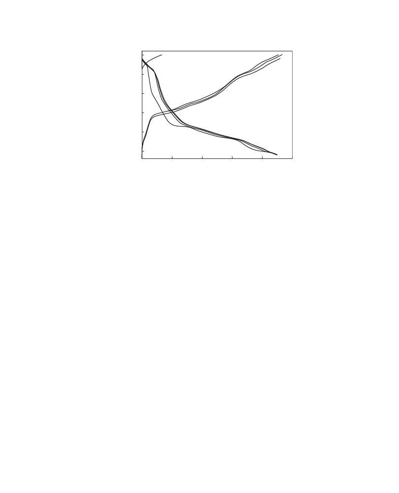
Moreover, the discharge curve profile of a graphite cell is almost flat and that of a hard
carbon cell is rather sloping (
). When the cutoff voltage is set at 3 V, as is the case
of conventional applications such as personal computers and cellular phones, the
discharge capacity is reduced. In
, the discharge capacity of 2 V is defined as
100% and this chart shows that almost 12% of the discharge capacity is lost in case of a
hard carbon anode when the cutoff voltage is set at 3 V.
Of course, the discharge voltage can be electronically raised. But when the output
voltage is low, the discharge current must be increased to make up the required discharge
wattage.
We have understood from our experience of a hard carbon negative electrode that the
following factors are essential when we choose electrochemical cell materials, especially
active materials for positive and negative electrodes:
1. The volumetric energy density is important as well as the gravimetric one, because,
in general, the cell size is predetermined. The material with the lower specific density
is not preferable from this point of view.
Chapter 2 • Past, Present and Future of Lithium-Ion Batteries 25
2. The cutoff voltage influences the discharge capacity. A cell with a sloping discharge
profile is disadvantageous.
3. The initial charge and discharge efficiency should be as high as possible.
4.
Improvement of LIB
To catch up with the required volumetric energy density, we introduced a graphite
negative electrode into our third-generation LIBs. The latest 18650 cell has energy
densities of 230 Wh/kg and 620 Wh/dm
3
.
To further improve the energy density, novel active materials for both negative and
positive electrodes must be investigated.
4.1.
Sn-based Anode
Sony developed a novel negative electrode based on a tin alloy which consisted of Sn, Co
and C. The new cell system was named Nexelion
.
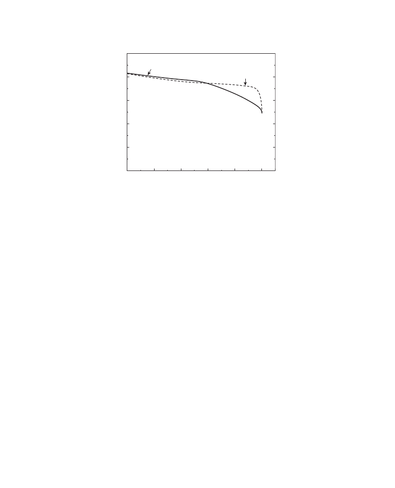
shows the temperature effect on the discharge capacity of Nexelion and it
was claimed that Nexelion had 30% higher discharge capacity than cells with a graphite
anode. The increase in discharge capacity, however, was
w15% at a cutoff voltage of 3.0 V,
as shown in
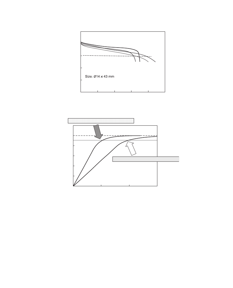
shows the charging characteristics of Nexelion. About 90% capacity could
be charged in 30 min at the 2C rate, corresponding to a 50% higher charging speed
compared to current LIBs.
Hard carbon / LiCoO
2
0
20
40
60
80
100
0.0
1.0
2.0
3.0
Voltage (V)
Discharge capacity (%)
4.0
5.0
Graphite / LiCoO
2
FIGURE 2.2 Discharge curve pro
files of graphite and hard carbon.
26
LITHIUM-ION BATTERIES: ADVANCES AND APPLICATIONS
The size of the first generation of Nexelion (launched in 2005) was very small,
Ø14
43 mm, and the capacity was only w800 mAh (4.2–3.0 V).
Sony introduced a prismatic cell (11
30 42 mm) in 2007 with a larger capacity of
w1800 mAh (4.3–3.0 V) and, in 2011, succeeded in the development of 18650 Nexelion
cells. They have a capacity of 3000 mAh (in the range 4.3–3.0 V), resulting in energy
densities of 210 Wh/kg and 670 Wh/dm
3
.
When the cutoff voltage is set at 2.0 V, the discharge capacity is 3500 mAh, the
gravimetric energy density is 225 Wh/kg, and the volumetric density is 720 Wh/dm
3
.
1
2
Discharge voltage (V)
3
4
5
0
0
200
400
Discharge capacity (mAh)
600
800
1000
0 °C
Sony’s conventional cell
Nexelion
23 °C 0 °C 23 °C
Discharge current: 0.5C
FIGURE 2.3 Discharge curves of Nexelion.
0.0
0
20
40
60
SOC (%)
80
100
0.5
Charge time (h)
50% High charging speed than current Li-ion
Model : 14430
Charge at 1C/2C
Room temperature
90% Capacity by 30 min charging at 2C
1.0
1.5
90% Capacity by 60 min charging at 1C
Nexelion
FIGURE 2.4 Charging characteristics of Nexelion.
Chapter 2 • Past, Present and Future of Lithium-Ion Batteries 27

4.2.
Si-based Anode
The charge/discharge capacity of graphite has reached practically its theoretical limit and
new anode active materials are being aggressively investigated to improve the cell
capacity. The tin-based anode of Nexelion is one example; silicon is another candidate for
high-capacity anodes.
The theoretical discharge capacities of LiC
6
, Li
4
Si and Li
4.4
Sn are 339, 1908 and
993 mAh/g, respectively, which means that the Si-based anode is very attractive.
Si, however, involves a fundamental drawback that needs to be overcome first. When
Li is doped into Si, Si expands hugely by
w300%. The repeated volume expansion during
cycling brings about pulverization of Si and a sharp capacity decay due to the loss of
electric contacts between resulting Si fine particles.
SiO has been tried in place of Si, because the expansion rate is smaller than that of Si
and thus a better cycle performance is expected. The capacity decline during cycling is
decreased significantly. This material, however, poses a different problem. The charge/
discharge efficiency during the first cycle is very low,
w50–75%.
Further investigations are crucial to improve the performance of anodes based on Si
before putting them into practical use.
4.3.
Ti-based Anode
Li
4
Ti
5
O
12
(hereafter LTO) is a new type of LIB anode material with peculiar characteris-
tics. The Li insertion potential of LTO is higher than that of graphite, namely, about 1.55 V
(vs. Li/Li
þ
) and this prevents Li plating on the anode surface even when LTO is charged at
high rates. Moreover, the volume change is very small during Li doping and undoping.
These features provide the resulting LIBs with good drain capability, fast charge
acceptance and excellent cycle performance.
The great drawback of LIBs with an LTO anode is their low terminal voltage, namely,
w2.2–2.5 V with cathodes such as LCO, LiMn
2
O
4
or LiNi
1/3
Co
1/3
Mn
1/3
O
2
, which means
that the energy density of an LTO cell is considerably lower than that of conventional LIBs.
About 1.5 times as many LTO cells as conventional LIBs are required to prepare a
battery system with the same voltage. When a 300-V power system, for example, is
designed, 120 LTO cells should be connected in series, but only 80 cells in the case of
conventional ones are needed. This means that a much more complicated battery
management unit is necessary in the LTO system.
4.4.
LIB with Gelled Polymer Electrolyte
Electrolyte leakage has been one of the most annoying problems in primary and sec-
ondary cells and the immobilization of electrolyte has been considered effective against
the leakage.
Pure polymer electrolytes, which consist of a polymer matrix and Li salts, have only
low ionic conductivity, and gelled polymer electrolytes (GPEs) have been investigated
28
LITHIUM-ION BATTERIES: ADVANCES AND APPLICATIONS

intensively by many researchers to improve conductivity. GPEs are composed of polymer
matrices and solvents or plasticizers and they have so high ionic conductivity that they
can be used as solidified electrolytes of LIBs in place of pure polymer electrolytes.
Sony developed lithium polymer batteries (LPBs), namely, LIBs with GPEs, and
introduced them into the market in 1998
.
It has been widely said that the drain capability and low temperature performances of
LPBs compare unfavorably with LIBs due to the poor ionic conductivity of GPEs and that
they cannot have sufficient performance as power sources for portable electronic
equipment.
Keeping these concerns in mind, we fixed our concepts and targets as follows when we
began our developmental program of LPBs:
1. Low vapor pressure of solvents from gelled electrolytes.
2. Good adhesiveness of gelled electrolytes to active electrode materials.
3. All the solvents are confined within polymer matrices and no free organic solvent is
present, thus preventing electrolyte leakage.
4. GPEs have high ionic conductivity in a wide temperature range, especially at low
temperatures.
5. Plastic film is used as an envelope for the electrode element which constitutes an
insuperable barrier against solvent vapor permeation and moisture infiltration.
6. Comparable performances to conventional LIBs.
GPEs need to have two incompatible properties. They are required to be able to hold as
much solvent as possible in order to increase ionic conductivity. On the other hand, high
mechanical strength is also essential. Too much solvent causes fragile gels.
We have developed gel electrolytes which consisted of block copolymer of vinylidene
fluoride and hexafluoropropylene as the matrix resin with ethylene carbonate (EC)/
propylene carbonate (PC)/LiPF
6
as the electrolyte solution and it has been proved that
they have sufficiently high ionic conductivity and high mechanical strength to realize the
concepts listed above
.
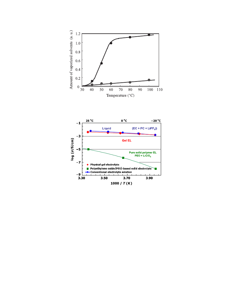
GPEs contain organic solvents as plasticizers and the reduction of vapor pressure is
crucial. The amount of vaporized solvents from our GPE was measured in the experiment
described here. Microporous polyethylene separator and the polymer matrix were soaked
in the electrolyte solution and heated at various temperatures for 60 min. The vapor
amounts from both samples were measured and compared.
clearly shows that
the vapor pressure of solvents in our GPE was significantly low even at the temperature of
100
C, while microporous separator could hold the solution at low temperature probably
due to large surface tension in the micropores, but vaporization of solvents increased
steeply as the temperature rose.
shows the ionic conductivity vs. temperature of a GPE in comparison with
that of the liquid electrolyte with the same solvents and salt.
It is widely recognized that PC decomposes spontaneously during lithium intercala-
tion into graphite. Consequently, EC-based electrolytes are commonly utilized in LIBs
Chapter 2 • Past, Present and Future of Lithium-Ion Batteries 29
with graphite anodes. PC-based electrolytes, however, show higher ionic conductivity
than EC-based ones and thus it is convenient to use PC as a plasticizer to improve the
electrolyte conductivity.
In our LPBs, surfaces of graphite particles were modified with amorphous carbona-
ceous materials to avoid PC decomposition and our GPEs had comparable ionic con-
ductivity to liquid nonaqueous electrolytes and also exhibited excellent compatibility
with graphite.
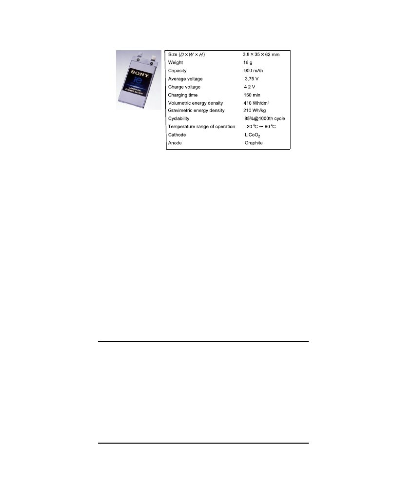
shows the characteristics of Sony’s LPBs as of 1998; their performance was
similar to that of LIBs of those days. The gravimetric energy density of LPBs was especially
attractive, thanks to the adoption of a lightweight aluminum-laminated polymer film as
casing material instead of a heavy metal can.
Electrolyte solution
held in separator
Gelled electrolyte
FIGURE 2.5 Vapor pressure from GPE.
electrolyte(EL
FIGURE 2.6 Arrhenius plot of ionic conductivity of different electrolyte materials. (For color version of this
figure, the
reader is referred to the online version of this book.)
30
LITHIUM-ION BATTERIES: ADVANCES AND APPLICATIONS
In
, characteristics of one of the recent LPB models are shown for compari-
son. The volumetric energy density is improved considerably in spite of smaller size
compared to the 1998 model.
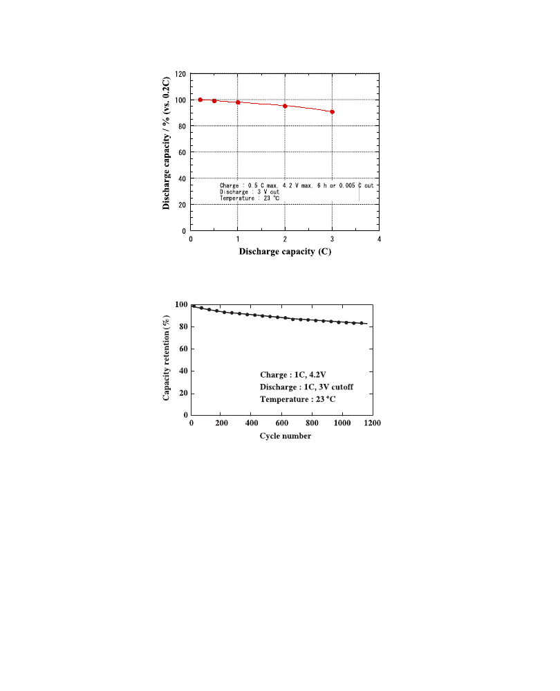
Drain capability is shown in
and the discharge capacity retention (capacity
at 0.2C rate
¼ 100%) is plotted against the discharge rate; a retention of 90% is obtained
even at the 3C rate, comparable to that of LIBs.
shows the cycle performances of LPBs. Capacity retention at the 1000th
cycle is around 85% and this value is much better than that of conventional LIBs.
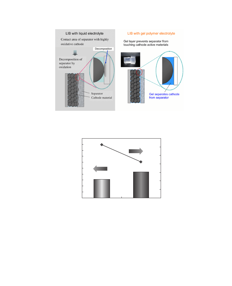
The separator used in LIBs might be degraded by physical contact with high-voltage
positive electrode materials. The polyolefin separator is oxidized and gaseous products
are produced, which causes swelling of the so-called pouch cells.
In case of LPBs, however, gelled electrolytes exist between positive electrode materials
and separators, thus preventing the direct contact mentioned above and depicted in
FIGURE 2.7 Characteristics of Sony
’s LPB as of 1998. (For color version of this figure, the reader is referred to the online
version of this book.)
Table 2.1
Characteristics of the Latest LPB Developed by Sony
Size (D
W H)
3.8
34 50 mm
Weight
14.5 g
Capacity
830 mAh
Average voltage
3.75 V
Charge voltage
4.2 V
Charging time
150 min.
Volumetric energy density
475 Wh/dm
3
Gravimetric energy density
215 Wh/kg
Cyclability
85%@1000th cycle
Temperature range of operation
20
C
w 60
C
Cathode
LiCoO
2
Anode
Graphite
Chapter 2 • Past, Present and Future of Lithium-Ion Batteries 31
. Therefore, no swelling can be observed on storage at high voltage and
temperature, contrary to what happens for LIBs (
4.5.
LIB with LiFePO
4
Cathode
Sony has developed LIBs with high drain capability utilizing LiFePO
4
as a cathode active
material
. The nominal voltage of the graphite/LiFePO
4
cell is 3.4 V.
Although the energy density of a 18650 cell (1100 mAh) is rather small, about
95 Wh/dm
3
, discharge rates as high as 27C are possible, and a flat discharge curve profile
is maintained throughout discharge.
The cycle performance is also attractive. More than 90% of the initial capacity can be
retained even after 1000 cycles at the 9C discharge rate.
FIGURE 2.8 Drain capability of LPB. (For color version of this
figure, the reader is referred to the online version of
this book.)
FIGURE 2.9 Cycle performance of LPB.
32
LITHIUM-ION BATTERIES: ADVANCES AND APPLICATIONS
The performance at low temperatures is good. The capacity retention at
10
C is 95%
of the room temperature capacity at the 9C rate.
A larger cell, called 26650 size (Ø26
65 mm), has also been developed. Its capacity is
3000 mAh and its energy density is 113 Wh/kg. Its capacity retention after 5000 cycles at
the discharge rate of 1C is more than 80%.
Although the drain capability is moderate compared with the 18650 cell, a 10C rate
discharge is possible.
FIGURE 2.10 Comparison of effect by cathode materials on separator in conventional LIB and LPB. (For color version of
this
figure, the reader is referred to the online version of this book.)
Increase of cell
thickness
Storage 4.4 V 75 ºC 48 h
Recovered
capacity
100%
Recovery ratio of capacity (1C)
80%
60%
40%
20%
0%
4.4 V LIB
Electrolyte : EC/DEC = 3/7, LiPF
6
1 M
Increase of cell thickness (mm)
4.4 V LIPB
0
0.5
1
1.5
61.1%
87.0%
0.11
1.14
FIGURE 2.11 Storage test for LIB and LPB charged to 4.4 V.
Chapter 2 • Past, Present and Future of Lithium-Ion Batteries 33

5.
Can New Battery Technologies Open up Novel
Horizons for LIB?
Since the first introduction of lithium-ion batteries into the market in 1991 by Sony,
extensive improvements have been carried out.
The first commercialized LIB had energy densities of 80 Wh/kg and 200 Wh/dm
3
.
The energy densities of the latest version of LIBs are greater than 230 Wh/kg and
620 Wh/dm
3
.
It is recognized, however, that new technologies are essential to further improve LIB’s
performance, including energy density and safety characteristics. Thus, many new
technologies have been disclosed which are scientifically attractive. Some of them,
however, do not meet the requirements discussed in
. I would like to look at
some new technologies from this perspective.
In the following sections, I will discuss the conflicts between those requirements and
some of the new technology proposals.
5.1.
Positive Electrode with Excess Lithium
Active materials for positive electrodes with excess lithium are now the subject of our
attention because they are expected to have a large discharge capacity.
Li
2
MnO
3
is one of the candidates and the solid solution of LiMO
2
(M
¼ Co, Ni, Mn) and
Li
2
MnO
3
has been recently investigated. Nissan Motor Co. announced the development
of this type of active material for positive electrodes for LIBs
.
It was claimed that this material had about 300 mAh/g of discharge capacity, almost
twice that of LiCoO
2
. However, this solid solution showed poor cycle performance. In
order to improve the cycle characteristics of the solid solution, Nissan’s researchers have
performed electrochemical pretreatment. According to this, stepwise charge and
discharge cycles were carried out. The charge voltage was increased stepwise to 4.5, 4.6,
4.7 and 4.8 V, and at each voltage, the charge/discharge cycle was repeated twice, so a
total of eight charge/discharge cycles were performed.
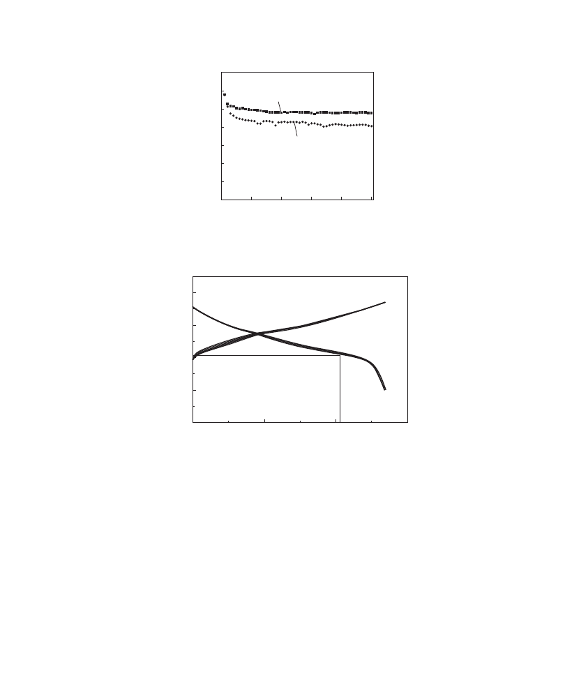
This electrochemical pretreatment improved the cycle performance of the solid-
solution cathode as shown in
. However, this pretreatment is not acceptable
from the mass production point of view because it is very complicated and time consuming.
shows the charge/discharge profiles of the resulting solid-solution cath-
ode. The discharge curve was rather sloping and when the cutoff voltage was set at 3.0 V,
the discharge capacity was around 200 mAh/g, much smaller than their claimed value of
300 mAh/g under the discharge rate of 1/12C.
5.2.
Organic Positive Electrodes
In general, materials for positive electrodes are inorganic compounds containing metals
such as cobalt, nickel or manganese. Organic compounds are attractive for positive
electrodes because no expensive metal is utilized.
34
LITHIUM-ION BATTERIES: ADVANCES AND APPLICATIONS
5.2.1.
Dithiooxamide
A novel active material was developed using dithiooxamide (commonly called
rubeanic acid [chemical formula, H
2
NCSCSNH
2
]). This material was evaluated using a
Li anode
and a Li predoped graphite anode
. It was reported to be free from
rare metals and to have a discharge capacity four times as large as that of LCO, e.g.
w600 mAh/g.
The specific gravity of this material is low, that is 1.66. The theoretical specific gravity
of LCO is 5.16.
The practical volumetric discharge capacity of rubeanic acid is calculated at
1000 mAh/cm
3
, and that of LCO is at 710 mAh/cm
3
assuming that its practical
density is 5.1.
Li[Ni
0.17
Li
0.2
Co
0.07
Mn
0.56
]O
2
With pretreatment
300
200
Specific capacity (mAh/g)
100
0
0
10
20
Cycle number
90% Capacity retention is achieved after 50 cycles
30
40
50
Without pretreatment
Voltage range : 2.0 – 4.8 V
Current rate : 1/12C rate
Temperature : 25 ºC
FIGURE 2.12 Cycle characteristics of LiMO
2
-Li
2
MnO
3
cathode with and without pretreatment.
Li[Ni
0.17
Li
0.2
Co
0.07
Mn
0.56
]O
2
Voltage range : 2.0 – 4.8 V
Current rate : 1/12C rate
Temperature : 25 ºC
1
0
100
Specific capacity (mAh/g)
E
(V vs. Li/Li
+
)
200
300
2
3
4
5
FIGURE 2.13 Charge
–discharge characteristics after pretreatment.
Chapter 2 • Past, Present and Future of Lithium-Ion Batteries 35
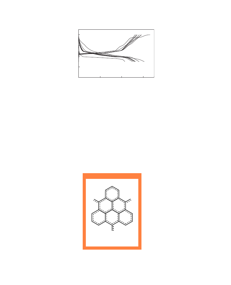
The discharge curve profile is sloping (
)
and the average voltage of the
Li/rubeanic acid cell is roughly assumed to be 2.5 V. The volumetric energy density can be
estimated at 2.5 Wh/cm
3
and that of an LIB with LCO at 2.6 Wh/cm
3
(average voltage,
3.7 V); thus, LCO is far from being behind rubeanic acid.
5.2.2.
Trioxotriangulene
An organic active material for LIB positive electrodes named trioxotriangulene (TOT)
(
) was reported in
Nature Materials
. The discharge capacity of the
tribrominated derivative of this material, Br
3
TOT, was 225 mAh/g, 1.6 times larger than
that of LiCoO
2
.
8←2
8←3
1
2
4
3
2
1
0
0
200
Capacity (Ah/kg)
Voltage (V)
400
600
1
FIGURE 2.14 Charge
–discharge curves of a rubeanic acid/Li cell (cutoff voltage: 1.5–4.2 V).
TOT
Trioxotriangulene
O
O
O
FIGURE 2.15 Trioxotriangulene. (For color version of this
figure, the reader is referred to the online version of
this book.)
36
LITHIUM-ION BATTERIES: ADVANCES AND APPLICATIONS
The discharge profile was sloping and the average discharge voltage was around 2.6 V
(
)
. The gravimetric energy density can be calculated as 0.585 Wh/g.
As the specific gravity was not disclosed, we assume a value of 2.0, which is rather large
for an organic material. In this case, the volumetric energy density would be 1.2 Wh/cm
3
,
only about 45% compared to that of LCO whose energy density is 2.6 Wh/cm
3
. Moreover,
if the cutoff voltage is fixed to 3.0 V, the discharge capacity would be less than 50 mAh/g.
So, this compound can hardly be considered practical and attractive as a cathode active
material, even if it is free from rare metals.
5.3.
Ceramic-Coated Separators
Safety is one of the most important issues of LIBs and several solutions have been pro-
posed. I would like to discuss here the effectiveness of ceramic-coated separators to
improve the safety characteristics of LIBs.
M. Alamgir prepared a separator, named safety reinforcing separator (SRS), whose
surface was coated with nanoscale ceramic particles
. When this separator was heated
to 150
C for 1 h, its shrinkage was very small, while the conventional polyethylene
separator shrunk drastically under the same conditions.
When a 450
C hot tip was pressed on to the conventional polyethylene separator, a
hole was formed that enlarged with time, while the hole formed on SRS was as small as
the tip and did not expand, thus indicating excellent thermal stability.
Mitsubishi Electric Corporation also developed a heat-resistant separator. Fine
alumina particles were mixed with PVDF and n-methyl-2-pyrrolidone (NMP) solvents
and the mixture was coated on the surface of the separator
. Mitsubishi reported that
lithium-ion batteries with this separator showed no internal short circuit even when
charged to 4.3 V and held at 150
C. On the other hand, lithium-ion batteries with the
conventional separator underwent an internal short circuit.
Average voltage after
the second cycle: 2.8 V
Average voltage: 2.6 V
0
2.0
3.0
4.0
100
Capacity (Ah/kg)
200
Voltage versus (Li/Li
+
V)
FIGURE 2.16 Charge
–discharge characteristics of TOT/Li coin cell.
Chapter 2 • Past, Present and Future of Lithium-Ion Batteries 37

Japan Vilene Co. Ltd and the National Institute of Advanced Industrial Science and
Technology (Kansai Center) developed a composite separator by lamination of the
nonwoven polyacrilonitrile nanofiber fabric and ceramic powder holding polyolefin
nonwoven fabric. In a hot oven test, the separator proved thermally stable at 150
C
.
In these three papers
, the separators were tested at temperatures of
150–160
C (and not above 160
C): it can be supposed that they evaluated the heat
durability of the binder used for the ceramics coating [PVDF], not the separator matrix
itself.
Sanyo’s researchers thought that the effectiveness of the heat-resistant separator with
ceramic particles was questionable and the following experiment was designed
. They
prepared a polyethylene separator coated with ceramic particles. The coating was made
of titanium dioxide with PVDF binder, and lithium-ion cells were constructed with LCO
cathode and graphite anode. Cells were fully charged and placed in a hot box heated up to
160
C. Both conventional separator and separator with ceramics coating led cells to
internal short circuit sooner or later. Sanyo concluded that the so-called heat-resistant
separator or the SRS is not effective in preventing internal short circuit when cells were
abnormally heated.
B. Barnett also showed that ceramics coatings can not eliminate the internal short
circuit and the thermal runaway
In conclusion, the ceramics-coated separator is not effective in preventing internal
short circuits when a cell is heated above the heat-resistant temperature of the binder
used. I feel no reluctance to admit that these separators contribute to the uniform tem-
perature distribution in the electrodes, because ceramic coatings are effective as regards
uniform heat distribution.
6.
Conclusion
New applications of lithium-ion batteries have been proposed, such as power sources for
electric vehicle, hybrid electric vehicle, plug-in hybrid electric vehicle, stationary power
sources, and so on.
In order to meet the requirements of these applications, recent technologies for
lithium-ion batteries have been reported.
Some reports, however, seem to disregard the practicability of new technologies
proposed, including the condition of utilization and the feasibility of mass production.
Nomenclature
ABS
Acrylonitrile-butadiene-styrene resin
EC
Ethylene carbonate
EV
Electric vehicle
FRP
Fiber-reinforced resin
GPE
Gelled polymer electrolyte
38
LITHIUM-ION BATTERIES: ADVANCES AND APPLICATIONS

References
[1]
Y. Nishi, J Power Sources 100 (2001) 101
.
[2]
M. Iguchi, T. Suehiro, Y. Watanabe, Y. Nishi, M. Uryu, J. Mater. Sci. 17 (1982) 1632
.
[3]
Y. Nishi, M. Uryu, New Mater New Processes 3 (1985) 102
.
[4] A. Omaru, H. Azuma, Y. Nishi, 182nd ECS Fall Meeting, Toronto, Canada, 1992.
[5] A. Omaru, H. Azuma, Y. Nishi, Japanese Patent Kokai 245,458 (1991).
[6] H. Azuma, H. Imoto, Y. Nishi, 182nd ECS Fall Meeting, Toronto, Canada, 1992.
[7] H. Inoue, 6th Shenzhen International Lithium-Ion Battery Summit, Shenzhen, China, 2011.
[8]
.
[9] H. Akashi, K. Tanaka, K. Sekai, 5th International Symposium on Polymer Electrolytes, Uppsala,
Sweden, 1996.
[10] Guohua Li, Presented at the 77th Shindenchi Koso Bukai, June 9, 2011 (in Japanese).
[11] Nissan Motor Co., Presented at Techno-Frontier-3, 2010 (in Japanese).
[12] M. Sato, T. Koizumi, Y. Miura, H. Mokudai, T. Sukigara, 51st Battery Symposium in Japan, Nagoya,
Japan, 2010 (in Japanese).
[13] M. Sato, H. Mokudai, T. Sukigara, K. Chiba, E. Kokubu, T. Kiryu, R. Okumura, N. Maruyama, 53rd
Battery Symposium in Japan, Fukuoka, Japan, 2012 (in Japanese).
[14]
[15] M. Alamgir, 26th International Battery Seminar and Exhibit, Ft. Lauderdale, Florida, USA 2009.
[16] M. Furukawa, 22nd Switching Power Sources and Battery System Symposium, Tokyo, Japan, 2007
(in Japanese).
[17] T. H. Cho, H. Ohnishi, Y. Kondo, Y. Miyata, T. Nakamura, M. Tanaka, H. Yamazaki, T. Sakai, 49th
Battery Symposium, Sakai, Japan, 2008 (in Japanese).
[18] Y. Baba, N. Imachi, S. Fujitani, 49th Battery Symposium, Sakai, Japan, 2008 (in Japanese).
[19] B. Barnett, 27th International Battery Seminar and Exhibit, Ft. Lauderdale, Florida, USA, 2010.
HEV
Hybrid electric vehicle
IT
Information technology
LCO
LiCoO
2
LIB
Lithium-ion secondary battery
LPB
Lithium-ion secondary polymer battery
LTO
Li
4
Ti
5
O
12
BMU
Battery management unit
PAN
Poly(acrylonitrile)
PC
Propylene carbonate
PET
Poly(ethylene terephthalate)
PFA
Poly(furfuryl alcohol)
PHEV
Plug-in hybrid electric vehicle
POM
Poly(oxymethylene)
PVDF
Poly(vinylidene fluoride)
Chapter 2 • Past, Present and Future of Lithium-Ion Batteries 39
Document Outline
- 2. Past, Present and Future of Lithium-Ion Batteries: Can New Technologies Open up New Horizons?
Wyszukiwarka
Podobne podstrony:
UFO,s Past, present and future
Education Past Present and Future
101 ielts speaking part two tasks about the past present and future
Connectionism Past, Present, and Future [jnl article] J Pollack WW
Computer Worms Past, Present, and Future
SHSBC418 The Progress and Future of Scientology
Is Hip Hop Dead The Past, Present, and Mickey Hess
Grammar EXTRA Inspired 1 Unit 3 Simple present and adverbs of frequency
Antonsson, The Present and the Past in the Sagas of Icelanders
Linear Motor Powered Transportation History, Present Status and Future Outlook
quiz past and future
There To be present and past
Kwiek, Marek The University and the State in Europe The Uncertain Future of the Traditional Social
LUNGA Approaches to paganism and uses of the pre Christian past
Gray The 21st Century Security Environment and the Future of War Parameters
PRESENT AND PAST
Corpus linguistics past, present, future A view from Oslo
Quattuor Coronati The Once and Future Science A Report on Hermetic Philosophy The Essential Teach
więcej podobnych podstron