
Instruction of connection and programming of the
OSCAR-N OBD CAN controller
Table of content
Paragraph
Description
Page
Introduction
2
1
Installation of OSCAR-N OBD CAN sequential gas injection system
4
1.1
OSCAR-N OBD CAN sequential gas injection system installation diagram
4
1.2
Proper installation of OSCAR-N OBD CAN ECU
4
1.3
Selection of pressure regulator
4
1.4
Selection of injectors’ nozzles diameter
4
2
OSCAR-N OBD CAN diagnostic program description
5
2.1
1. Choosing LPG or CNG work mode
5
2.2
2. Connecting controller to the PC
6
2.3
3. Main window content
7
2.4
4. Setting the basic parameters
8
2.4.1
5. Petrol Panel
8
2.4.2
6. Gas Panel
9
2.4.3
7. Switch Panel
10
2.4.4
Calibration Panel
12
1. 2.4.5
Oscilloscope Panel
14
2. 2.5
Other features available in the main window
15
2.5.1
Gas injectors' corrections
15
3. 2.5.2
Diagrams
16
2.5.3
Errors
16
2.5.4
Service
17
2.5.5
Load/Save
18
2.5.6
Languages
18
2.5.7
Calculator of injectors' nozzle diameter
18
2.5.8
Help
19
2.5.9
About us
19
3
Autocalibration
19
1. 3.1
Collecting the gasoline injection map with gasoline (gasoline map)
21
1. 3.2
Collecting the gasoline injection map with LPG (LPG map)
21
1. 3.3
Making correction to map by using multiplier. Calculating the adjustments
22
1. 3.4
Setting multiplier's adjustments manually
22
1. 3.5
LED switchboard
23
4. 4
Injection map correction depending on engine's RPM
24
5. 5
Advanced settings
26
6. 6
Reading OBD corrections using CAN bus
28
7. 6.1
8. OBD connector's description
30
1
OSCAR-
N
OBD CAN
Sequential gas injection controller of IV generation OSCAR-N OBD CAN was mainly
destined for modern cars, which have technologically advanced OBD2 system. It might be
also used in older types of cars. Thanks to its modern construction and highly efficient CPU
it gives possibilities to fulfill strict emission exhaust norms, keeping the driving dynamic
and performance identically as on petrol.
OSCAR-N OBD CAN gives possibility of making communication through digital serial bus
CAN. It gives possibility of diagnosing OBD of original car's petrol ECU from the level of
LPG controller's software.
Besides signals from original's petrol injectors controller uses additionally information from
car's OBD system (like vacuum, signals from both lambda probes, short and long term fuel
trims) to determine amount of gas needed in the particular moment. Controller reads the
parameters of mixture's correctors mentioned above and adjusts gas injectors opening times,
to make the „Short Time Fuel Trim” and „Long Time Fuel Trim” values oscillate between
values expected by the car's manufacturer.
The advance of such solution is possibility of calibrating LPG settings to obtain almost
identical characteristics of driving as on petrol. Controller reads the mixture correctors all
the time and automatically adjusts them to fulfill the EURO emission standards.
In OSCAR-N OBD CAN controller the unique algorithms of controlling LPG injectors has
been used. Injection opening time for each gas injector is being calculated individually, in
real time, basing on injection opening time of petrol injector corresponding to it. Thanks to
that solution efficiency and dynamics of driving on gas are practically identical like on
petrol. Another advantage of that solution is the fact that controllers works without any
problems with car's engines like HEMI (part of cylinders are being temporarily turned off
during work), Valvetronik (constant value of vacuum in the inlet manifold) and cars which
are having opening time differences between individual injectors (Subaru).
2

New controller advantages:
1) Possibility of connecting to CAN bus thought diagnostic plug (in cars which are having such
possibility).
2) Automatically making corrections of LPG injection opening time on base of parameters read
from original car OBD (in real time).
3) Calculation of injection opening time individually for particular gas injector basing on opening
time of adequate petrol injector.
4) The smallest device on the market of sequential injection gas system, which can control up to 8
cylinders. Aluminum case dimensions are: 130 (length) x 100 mm (width) x 28 mm (thickness).
5) The fastest digital signal processor ever used in sequential injection gas controller. It runs at
frequency 120MHz.
6) Automatic detection of petrol injection type signal.
7) Holding up working on gas during temporary lack of RPM signal.
8) Possibility of using temperature sensors with different impendancy.
9) Possibility of connecting and reading signals from two separate lambda probes.
10) built in anti-supertensions protection.
11) Advanced digital filtration of all input signals.
New software advantages:
1) Possibilities of reading original OBD parameters from CAN bus, modification of these
parameters and erasing OBD errors.
2) Possibility of collecting data for advanced mapping (fine tuning) without necessity of having PC
connected to the controller.
3) Extended possibilities of setting up the controller: calibration on idle, modifying the injection
opening time regarding vacuum in the inlet manifold, regarding to RPM and regarding to gas
pressure rapid changes.
4) Upgraded algorithm of autocalibration at idle (each cylinder calibrated individually).
5) New algorithms of preheating LPG injectors.
6) New algorithms of preventing car's engine from stalling during exits from „cut-off” (for the
turbocharged cars).
7) New algorithms which allows to operate in cars where petrol injectors are fully opened on high
revs (mainly tuned cars).
8) Wide range of compatible gas injectors.
9) Automatic detection of petrol injectors controlling type (sequence / semi sequence / full-group).
10) Possibility of setting distance remaining to service inspection.
11) Possibility of setting minimal injection opening time value of petrol injector which should be
directed to LPG injector.
12) Possibility of setting minimal LPG injector opening time.
13) Possibility of handling the cars controlled with +12V signal configured from the software.
14) List of car models which are capable to connect with OBD system through CAN bus.
15) Very simple and user-friendly software with advanced options (available on password) and built
in gas injector nozzle calculator.
16) Possibility of remote help in setting the parameters and calibration of the car through the
Internet by our Technical Department.
3
1. Installation of OSCAR-N OBD CAN sequential gas injection system
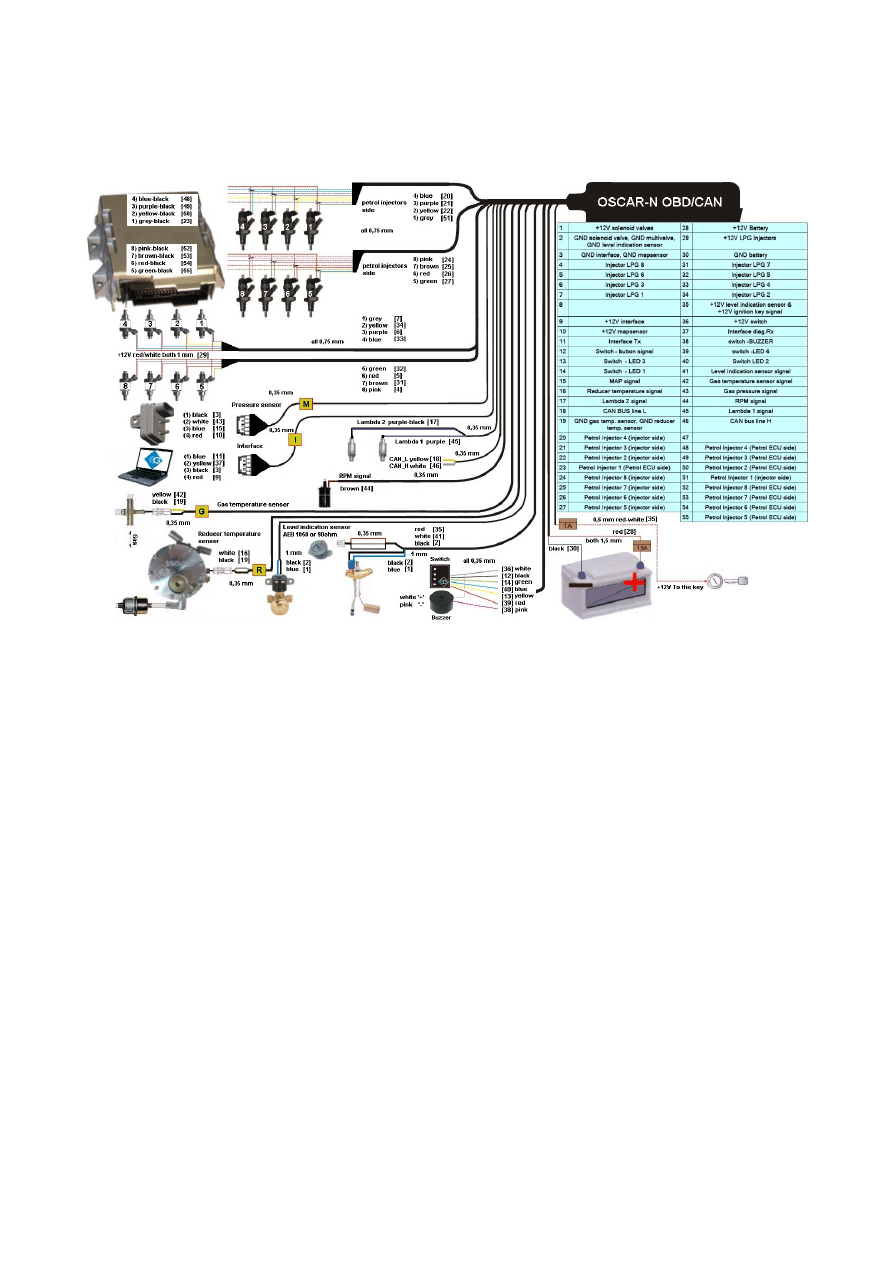
1.1 OSCAR-N OBD CAN sequential gas injection system installation diagram
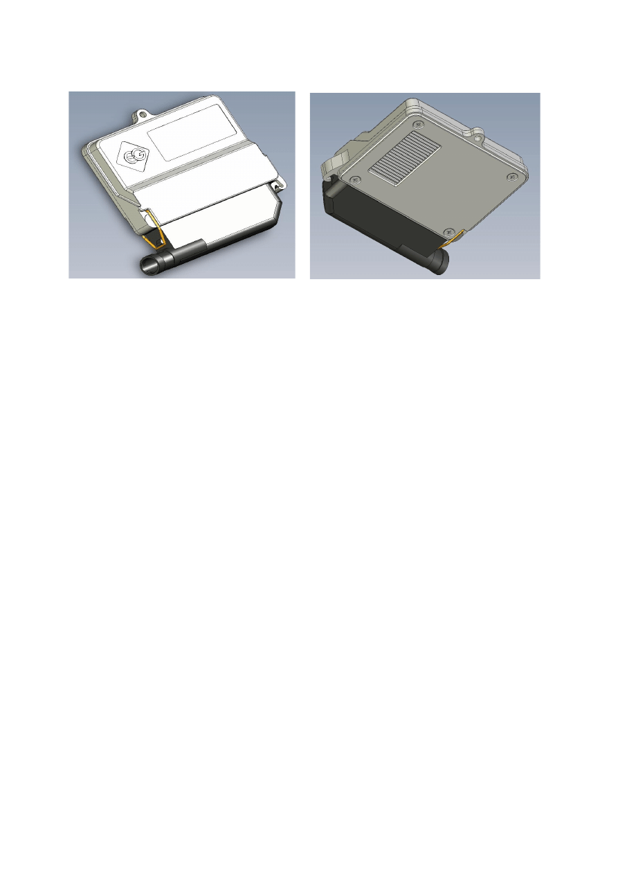
1.2. Proper installation of OSCAR-N OBD CAN ECU
During the installation of OSCAR-N OBD CAN sequential gas injection system it is
suggested for the wire set to point downwards. It is also suggested that it should be placed in such a
way to avoid the negative impact of high temperature and humidity.
1.3. Selection of pressure regulator
Connection of wiring should be performed according to the connection diagram. During
connection of the OSCAR-N OBD CAN sequence gas injection system pay special attention to
proper selection of a pressure regulator for given engine power and injectors’ nozzles. Improper
selection of the pressure regulator in relation to engine power will cause that when the LPG delivery
is high (i.e. the throttle fully opened) the pressure regulator will be not able to ensure nominal LPG
pressure and the pressure in the system will drop. If the LPG pressure will drop below the minimum
value set at the controller the system will switch over to supply with gasoline. For most of the cars
the pressure regulator should be regulated close to 1 bar (You can observe the this value in OSCAR-
N OBD CAN software).
1.4. Selection of injectors’ nozzles diameter
ATTENTION!
Injection rail type RAIL, VALTEK should be calibrated with a special calibration device
before installing it in the car. Calibration is needed for checking the piston stroke which must be
4
equal for all of the cylinders. For shorter times of injection (2,0 – 2,6 ms) it is recommended setting
smaller piston stroke which should be between 0,40 – 0,45 mm. For longer petrol injection timings
(3,0 – 4,0 ms) the piston stroke should be between 0,45 – 0,65 mm.
Selection of injectors’ nozzles diameter depends also on the engine power. The injectors’ nozzles
should be selected in such way so that at high engine load and high RPM the multiplier for given
injection time should be close to 1. Most engines have injection times amounting to 15 [ms]. The
table below contains list of nozzle diameters depending on power for 1 cylinder. To read out the
nozzle diameter for given engine correctly it is necessary to divide the engine power by number of
cylinders.
Nozzle diameter [mm]
Reducer's pressure 1 [bar]
Power for 1 cylinder [HP]
1,8-2
12 – 17
2,1-2,3
18 – 24
2,4-2,6
25 – 32
2,7-2,9
33 – 40
3,0
41 – 48
Pay special attention that the figures in table are only rough values and in some cases may not
agree with real ones.
Such situation can appear in vehicles fitted with semi-sequential or full group (all injectors activated
simultaneously) injection. In such vehicles nozzle diameters will be smaller than these given in the
table due to the fact that in such type of LPG supply control the volume of supplied LPG is greater
than for full sequence – twice for the semi-sequential and four times for full group injectors. For
selecting the size of injectors adequate to engine horsepower injection nozzle calculator (built in the
software) might be used.
2. OSCAR-N OBD CAN diagnostic program description
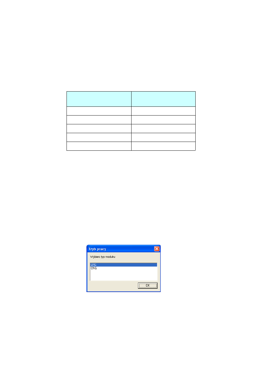
2.1 Choosing LPG or CNG work mode
During every start of the software please choose the OSCAR-N OBD CAN ECU work mode
LPG or CNG (depending on the type of installation in the car).
5
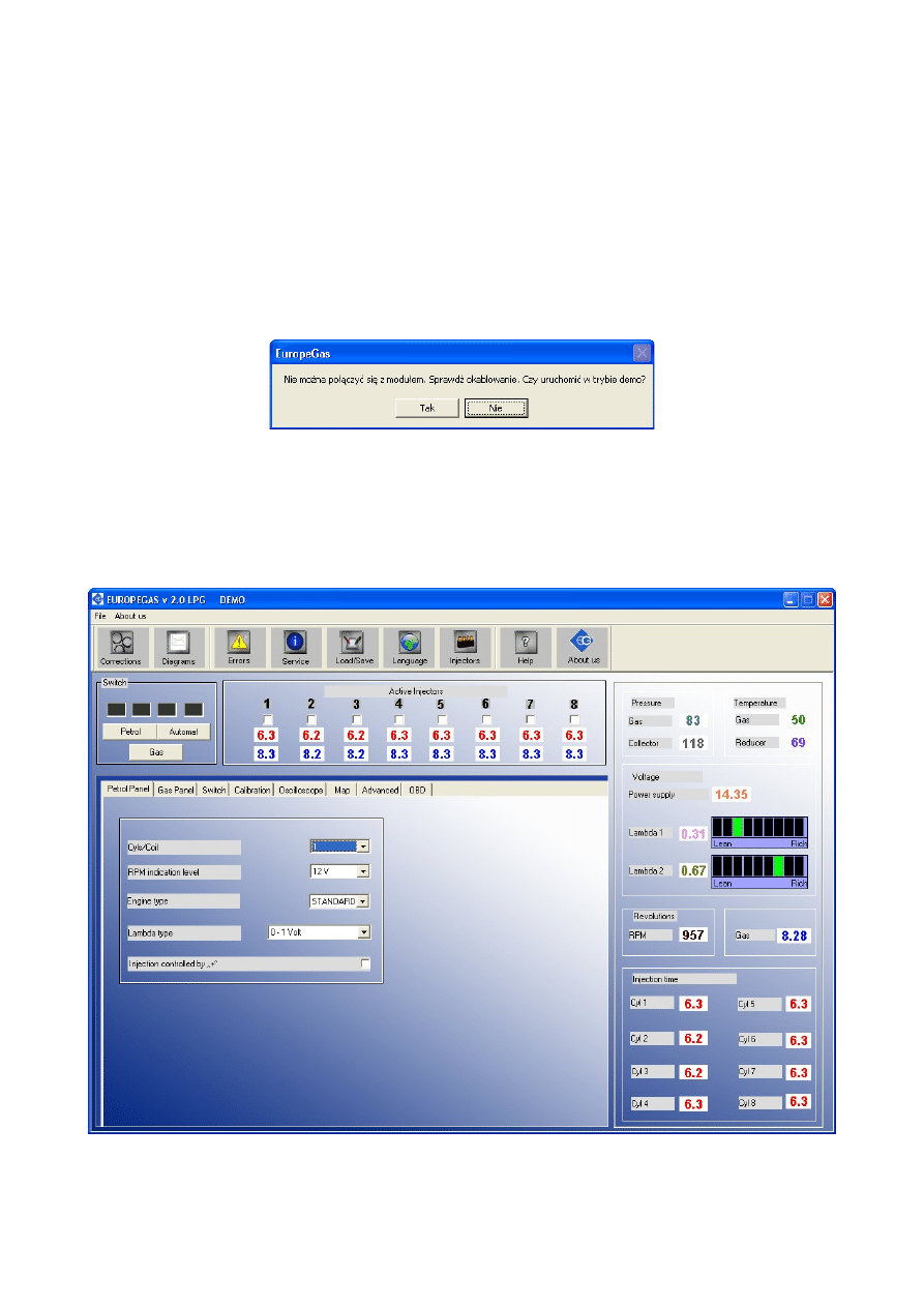
2.2. Connecting controller to the PC
If the all the connections are made correctly, connect OSCAR-N OBD CAN to the PC with installed
OSCAR-N OBD CAN diagnostic program, by using EUROPEGAS OSCAR-N interface (RS 232
or USB type). Before starting the program please turn on the ignition and start the car to
supply the controller with +12V voltage. This is necessary because without having power supply
the controller goes to the sleep mode, where the communication is impossible. That situation will be
signalised as connection error. In this situation software will propose to work in „Demo” mode,
which will simulate the work of software as the controller on working car would be connected to
the PC.
After starting the software automatically is searching all the COM ports. When it finds OSCAR-N
OBD CAN controller on one of the ports the communication the communication will be established
and software is ready to work. That fact is signalized by “Connected” message in the left upper
corner of the program main window. When the communication has been lost the message will
change to „No connection”. In demo mode the message „DEMO” will appear.
6

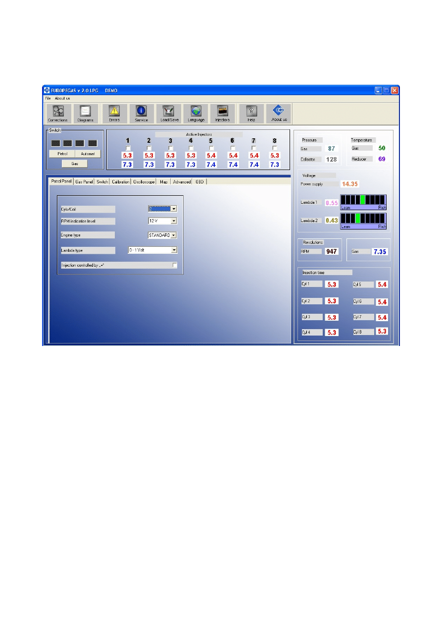
2.3. Main window content
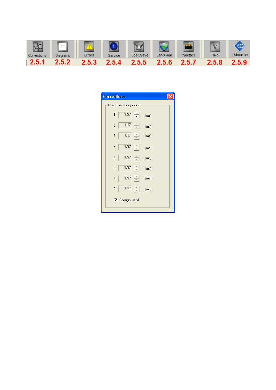
On the top of the main window there is bar with following icons:
Corrections -this option let us to change the time corrections/adjustment (in ms) of particular gas
injectors. Thanks to that option it is possible to correct the air/fuel mixture for particular cylinders.
Option useful especially for „V” type engines.
Diagrams -enlarges the calibration map and oscilloscope bookmarks to full size of main window
Errors -here we could read and erase list of errors registered in controllers memory.
Service -here we can read the ECU information about the controller like: time of work on petrol and
gas, date of last settings modification, service code of PC on which settings modification has been
made, time lasting to service inspection etc.
Load / Save -makes possible to read or write from/to *.xset file actual controller's settings, read
manufacturers setting and update firmware.
Languages -chooses the language version of software's interface
Injectors -Calculator of gas injectors nozzles for particular car. It bases on power of the engine (in
HPs), number of cylinders, injection type and type of fuel (LPG or CNG)
Help -Opens folder which contains controller harness installation diagram and this installation
manual in electronic form.
About us -Information about EUROPEGAS Sp. z o.o. company
Between the icons and Panels , on the left top side of the window, there are following groups:
“Active injectors” group - here we can turn off / on active LPG injectors which should be inactive /
active during work on LPG. If You disable separate injector by clicking with left mouse button on
the tick under the number of injector the adequate petrol injector will start working in its place,
while the rest of the cylinders will be working on LPG. This option is very useful for diagnostic
purposes. After turning off the ignition on next changeover to gas all gas injectors will be active
automatically.
Below the ticks of the active injectors You can find the injection times on petrol of adequate petrol
injectors (red colour) and calculated gas injectors opening time (blue colour) no matter on what
type of fuel car works in the moment. The values are read and calculated in real time for each
injector.
“Switch” group -the four squares always show the current gas indication level which is shown on
the switch in the cockpit. The Gas / Petrol button is used for instant changeover between both fuels.
The Auto mode turns controller in auto mode. It means that car will changeover to gas
automatically after 10 seconds (3 when “Fast Mode” is active) from fulfilling all the values required
for changeover i.e. temperature, RPM level, pressure etc. When the controller is in Auto mode the
red diode flashes. When it is on petrol the diodes are off. When it is on gas the diodes are on,
showing actual gas level indication set in the software.
On the right side of the OSCAR-N OBD CAN program window You can find actual indication of
most important system parameters: Gas pressure, vacuum in the inlet manifold, gas and reducers
temperature, voltage of controllers power supply, RPM, time of opening of petrol and gas injectors.
2 horizontal bars visualize the readings of two lambda sensors (if connected). We can enlarge these
parameters into full screen by pressing F10 button twice. In the left bottom part of main window we
can find the bookmarks, which groups the configurable system settings.
7
2.4. Setting the basic parameters
2.4.1. Petrol Panel
First step after connecting the interface from the computer to OSCAR-N OBD CAN ECU and
turning on the program is to set the parameters from the Petrol Panel properly.
No. of cylinders for one ignition coil – number of cylinders for one ignition coil (wrong
selection will cause improper indication of RPM signal)
Revolutions signal – revolutions signal source, +12 V – signal from the ignition coil, 5V –
signal from the vehicle’s ECU
Engine type – engine type, Standard – standard engine without supercharger, Turbo –
supercharged engine
Lambda Type -we can choose from 4 types of lambda probe(s)
Petrol Injection controlled with „+” - injection signals reading in systems where signals are
“positive”. In the most of cars injectors and being controlled by negative signal.
8
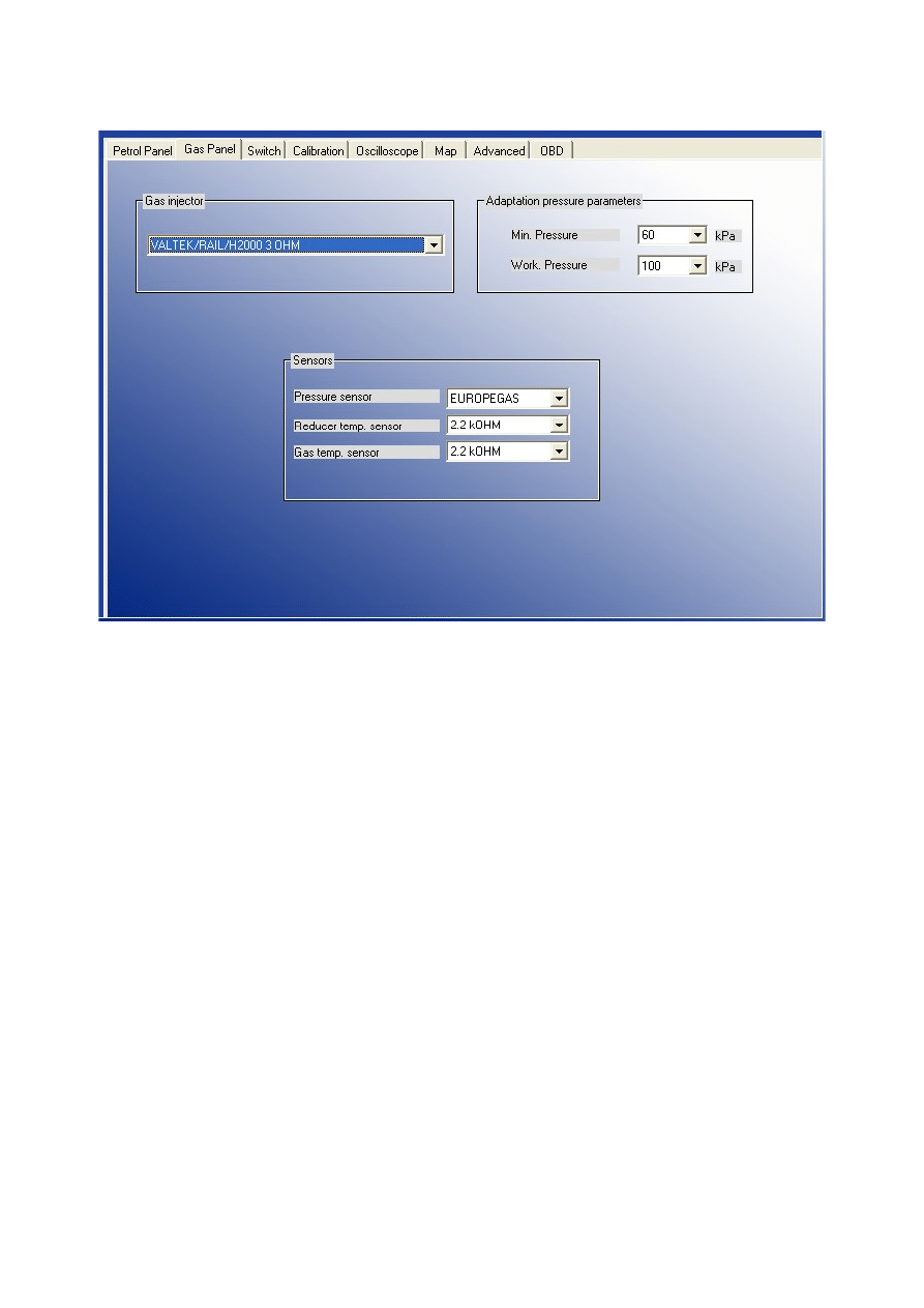
2.4.2. Gas Panel
Second step will be selecting the the proper injector rail type (for RAILGAS 3 Ohm injectors please
select VALTEK/RAIL/H2000 3 Ohm), and type of sensors from Gas Panel. Selection of wrong
sensor will cause improper sensor indication (i.e. wrong selection of gas temp. sensor may cause
showing very low reducer temperature on the screen after the start of warm engine)
Usually in OSCAR-N OBD CAN there are following sensors attached. Standard type of sensors
will be selected automatically after first controller connection with the PC (we can bring them up
with restoring the manufacurer's settings anytime) :
●
Pressure sensor – EUROPEGAS
●
reducer temperature sensor – 2.2 kOHM
●
gas temperature sensor -2.2 kOHM
Attention: In case of connecting reducer or temperature sensors from Magic Jet or Magic Compact
reducer 4,7 kOHM sensors should be selected in field “reducer temperature sensor “
Calibration parameters are the parameters automatically set after autocalibration:
“Minimum pressure” is the lowest border of gas pressure value (standard value is 60kPa) which is
being set during autocalibration. If the gas pressure will fall below this value, for time longer than
value set in „Pressure error time”, but the gas level in tank is bigger that 50%, controller will
signalize that gas pressure is too low by signal of buzzer, changing over back to petrol and waiting
for conditions to changeover back to gas (in „Auto mode”). It is being considered as temporary drop
of pressure but not empty tank (there will be no „Low gas pressure” error stored in the controllers
memory).
9
If the pressure drops down to 20kPa (it is being registered as empty gas tank) controller will
signalize it by buzzer sound and flashing red diode, and will changeover to petrol permanently.
However the user can press the switch changeover button and go back into “Auto mode” again.
“Working pressure” is the value of gas pressure during last autocalibration on idle.
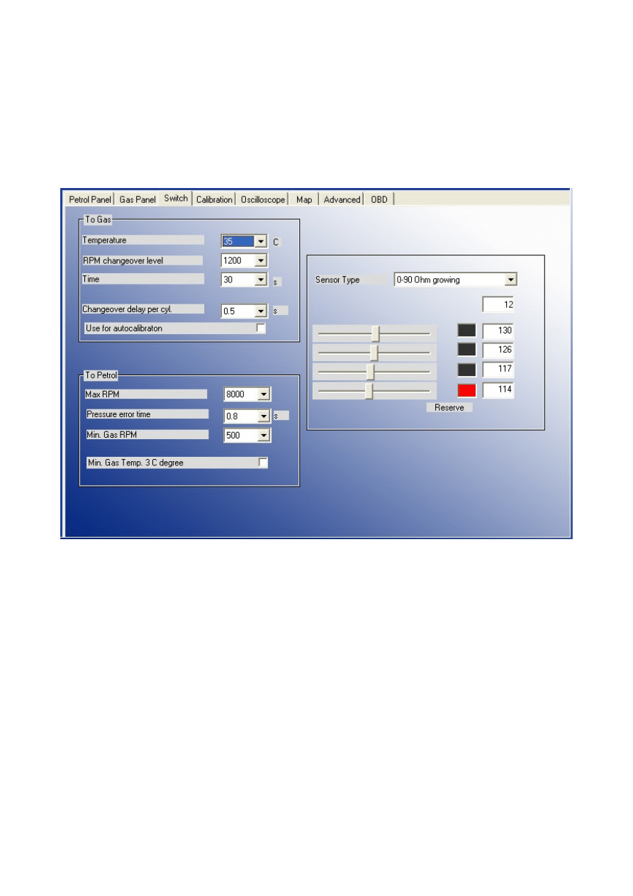
2.4.3. Switch Panel
Next stage is the the Switch settings group which contains the following parameters:
TO GAS
-parameters related with changeover from petrol to gas
Temperature – pressure regulator minimum temperature required for controller’s first
changeover to LPG. Controller will be waiting with change over to LPG until the gas
temperature will reach this level
RPM changeover level-engine RPM required for the controller to changeover to LPG.
Time – additional time period which will be added to “changeover to gas” time from cold
engine (if reducers temperature is lower than 50 C degree)
Changeover delay per cyl.– time between changeover between subsequent cylinders. In
example: when this parameter is set at 0.2 [s] the change over of a 4-cylinder engine from
gasoline to LPG or from LPG to gasoline will last 4*0.2[ms]. This option works regardless
of the fact that the gasoline injection system is the so-called full sequence or not. When this
parameter is set to 0 [ms] all the cylinders will changeover to gas / petrol at the same time.
10

Attention: During autocalibration this setting is ignored by default. Default value of delay during
autocalibration is 0 [ms]. However if engine stalls during changover of all cylinders to gas at the
same time we should increase this value (for example 1,5 s) and check in the field “Use for
autocalibration”. It will cause changeover from petrol to gas and from gas to petrol with the
entered time delay between subsequent cylinders changeover during autocalibration.
TO PETROL
-parameters related with changeover from gas to petrol
Max RPM – maximum level of engine's RPM at which car can run on LPG. Exceeding this
level will cause changeover to gasoline. When the RPM will fall back below this level the
car will go back to gas.
Pressure error time – time period (in ms) while the LPG pressure could be lower than the
“minimum pressure” value. If the pressure error will last longer than this time period the car
will change over to gasoline from low gas pressure.
Min. gas RPM -lowest border of engine's RPM at which the car could run on LPG. If the
RPM will fall below this level the car will change over to gasoline.
Min. gas Temp. 3 C degree – enabling this option makes the car to temporarily changeover
to gasoline for 30 seconds period every time when gas temperature will fall down below 3 C
degree (during this changeover the diode flashes constantly once per second). After 30
seconds, if gas temperature will be higher than 3 C degree, car changeovers back to gas.
Attention: Changeover to petrol due to exceeding above parameter's values (besides Min. gas
Temp. 3 C degree) is being realized by closing the injectors, without closing the solenoid valves.
Only visible effect will be temporary turning off the switch diodes (during drive on petrol) and
turning them up again (during drive on gas).
Attention: After turning the engine on controller automatically goes into „Auto mode”. It means
that after turning on, if the reducer temperature has reached min. 50 C degree, the controller waits 5
seconds to open the solenoid valves and another 5 seconds to open the first injector. Additionally we
need to add time of Changeover delay per cyl. to full changeover to gas. Time of delay of “Auto
mode” can be reduced from 10 downto 3 seconds, by activating “Fast mode” in Advanced
bookmark.
Sensor type -characteristics of level indication sensor installed on the tank's multivalve. We can
choose from four predefined 50 kOhom (falling/growing), 0-90 Ohm (growing/falling) level
sensors (RESISTIVE types) and two types of CNG Hall pressure gauges (VOLTAGE types)
By using the sliders below we can also set the levels at which the particular level diodes on the
switch will turn on and off. The status of particular diodes depends on the electrical signal readout
from the level indication sensor. That value is always shown in the OSCAR-N OBD CAN program,
below the sensor type selection field. The setting defined by user will be automatically stored in
controllers memory. We can restore the original settings anytime by restoring the manufacturers
settings.
Signal of gas level from the sensor is being shown in the software without averaging. On the switch
gas level is shown with averaging of 60 seconds, so the change made in the software will be present
at the switch dashboard after that period. Thanks to averaging the LPG level is not changing rapidly
when car is taking the curves and the multivalve in tank is floating fast up and down very quickly.
11
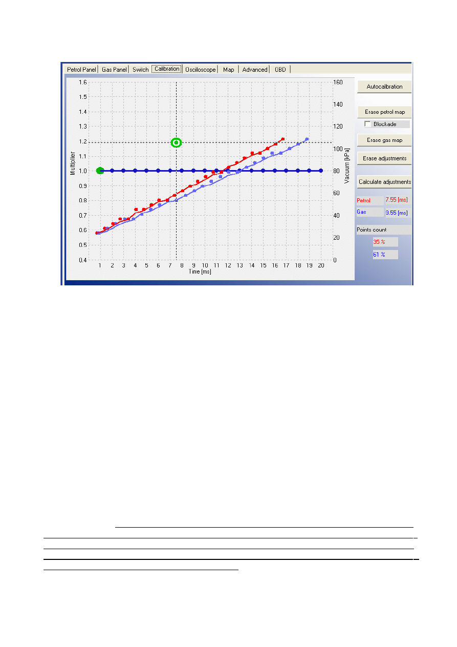
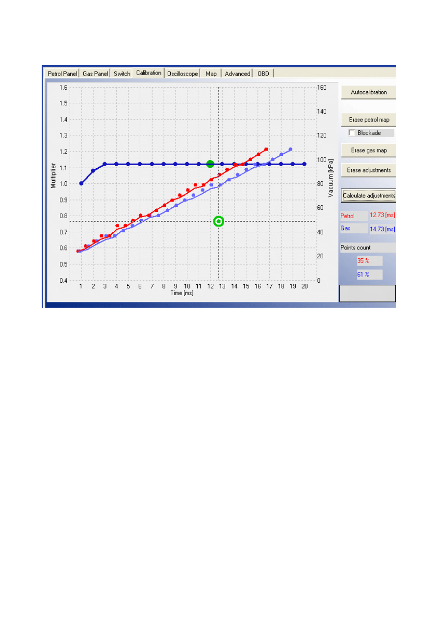
2.4.4 Calibration Panel
In Calibration panel there is map of gas controller showing dependency of petrol injectors opening
time on petrol (red points) and on gas (blue points) [ms] related to value of pressure (vacuum) in the
inlet manifold of the car [kPa]. On the right side of the screen we can see the first petrol (red colour)
and first gas injector (blue colour) opening time value [ms] and progress bar of autocalibration.
Green square on the map shows the actual values of pressure and petrol injectors opening time.
Left axis is the for the Multiplier line (blue) which sets the elongation of injection opening time of
petrol injector on gas (light blue points)
The following buttons are available:
•
Autocalibration -calculates the time correction for gas injectors on idle. Function described more
precisely in Chapter 3 of this manual.
•
Erase petrol -erases the map of petrol injection opening times on petrol from controller's memory.
•
Blockade -from the moment of turning that option on, no more points will be collected on the
petrol map.
•
Erase gas -erases the map of petrol injection opening times on gas from controller's memory.
•
Erase adjustments -automatically sets value for all points of multiplier to 1.0.
•
Calculates adjustments -automatically calculates and sets the line of multiplier to level the
difference between petrol and gas maps.
Attention: Below we can find values of filling percentage of petrol and gas map buffers in ECU
memory. When these values are above 100% no more points for petrol / gas will be collected in the
application screen. It is reccomended to erase the petrol and gas map after each autocalibration
and to erase the gas map after every change of multiplier. Before every another
autocalibration
i
t
is strongly recommended to erase all eventual earlier multiplier corrections,
by pressing the „Erase adjustments” button, otherwise the main correction from
Autocalibration might be not calculated properly.
12
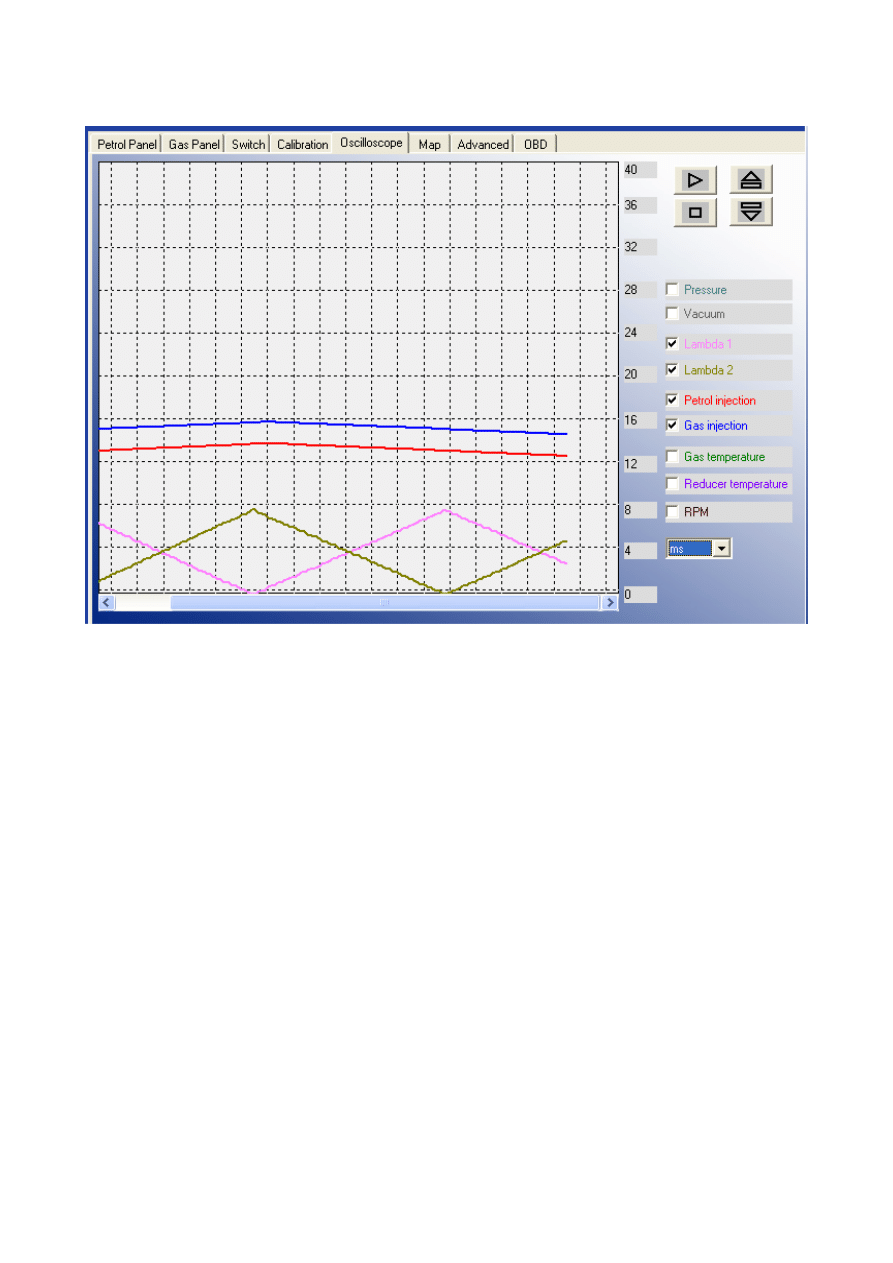
2.4.5 Oscilloscope Panel
On the right side of this panel we can select which signals measured by the controller we would like
to see on oscilloscope and the buttons for Load, Save, Start and Stop the oscilloscope. We can work
with following signals:
Gas pressure – LPG pressure value (pressure difference between the pressure regulator and
the suction collector)
Vacuum – MAP -pressure value within the inlet manifold (the absolute pressure value)
Lambda 1 voltage – voltage at the lambda 1 probe
Lambda 2 voltage – voltage at the lambda 2 probe
Petrol injection – petrol injection opening time
Gas injection -gas injection opening time
Gas temperature – LPG temperature at the pressure regulator outlet
Reducer temperature – temperature of the liquid gas within the pressure regulator
RPM [rev/min] – engine revolutions per 1 minute
All signals described above are visible on the oscilloscope and can be turned on and off
anytime. After pressing “Pause” button the lines stop being drawn. This option can be used for
checking what were earlier indications of signal. Below we can turn on the values of measurement
for the parameters which we would like to see the values in particular moment (on the screen above
we can see injection opening time of petrol and gas in ms)
13
2.5 Other features available in the main window
2.5.1 Gas injectors corrections
In this window we can read and adjust time corrections calculated for each injector during
autocalibration. These settings enable a correction of the fuel mixture for each cylinder. When
option „Change for all” in unchecked we can use it to correct the injection time variations present
in a “V” type engine cylinders. To calibrate the injectors, use the following procedure: Upon auto-
calibration, check the gasoline injection times for each cylinder when using gasoline. Turn the
LPG injectors on, one at a time, and observe if there are any differences in the injection times after
switching from gasoline to LPG. Adjust the correction time [ms] settings (only when necessary!)
for each injector so that switching to LPG one injector at a time will not result in changing the
gasoline injection times.
ATTENTION !!! Use this option as a last resort, i.e. when sure that the installation was
performed properly, all mechanical issues have been eliminated and injection times variations
for given injectors are still present when using LPG. Do not ever use injection strip-collector
pipes of different lengths and then the injectors’ calibration to accommodate this difference!!!
Also never use this option when the system is not in a perfect working condition or when some
of its elements have worn out. Using this option in a manner not consistent with the above
instructions may result in damage to the car!!!
14
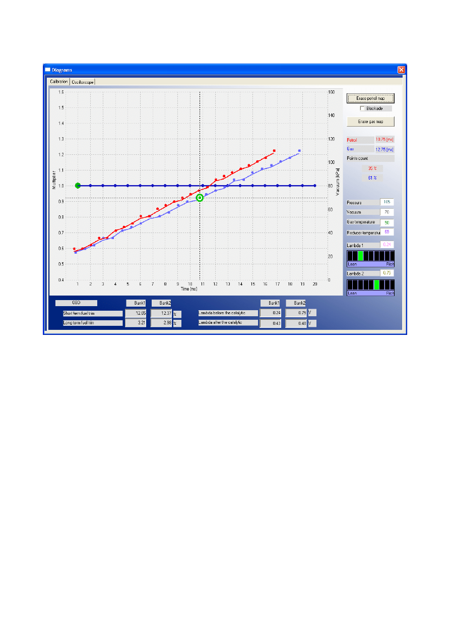
2.5.2 Diagrams
This function makes available to work with Map and Oscilloscope bookmark maximized to the
size of main window. This feature is recommended during collection of petrol and gas map.
2.5.3 Errors
Error appearance is signalized by beeping from a buzzer (if connected) and changeover back to
petrol. The diode on the switch will start blinking. In the software window the red dot will appear
on the “Errors” icon. After clicking that icon by left mouse button the “Errors” window will
appear. The Error window shows the following fields:
●
“Erase Errors” -this option makes available to erase errors which have occurred
●
„Continuous signal for errors” – if selected, acoustic signals will inform of an error until
manually turned off by the user. If unselected, the acoustic signal will appear only once for a
short period of time.
List of errors which might occur:
„Pressure sensor error” -pressure error is being signalized when the pressure drops down below
the value of 20 kPa. Situation like this happens when the gas tank is nearly empty. In case if the
value of pressure is not that low, but it's below the „Minimum pressure” value set in the application
(default it's being set at 60 kPa) it is being considered as end of gas, and controller changeovers to
petrol, but it is not registered as pressure error.
15
Attention: „Pressure sensor error” is the the only error which is being signalized by buzzer.
„No RPM signal” -In case of lack of RPM signal for short duration (below 4 seconds), the gas
injectors are being closed and car automatically goes back to petrol. Error of „No RPM signal” is
being registered in the controller. If the RPM signal will appear again before the 4 seconds period,
the car will automatically go back to gas. If after 4 seconds there still won't be RPM signal, the
solenoid valves will shut off. After receiving RPM signal again the controller will go in „Auto
mode” (waiting for changeover to gas).
„Gas temperature sensor error” -happens in case of reading to value our of range from gas
temperature sensor (might be caused by disconnected or damaged sensor).
„Reducer temperature sensor error” -happens in case of reading to value our of range from gas
temperature sensor (might be caused by disconnected or damaged sensor).
„Power voltage supply too low” -the controller power supply has fallen below 9 [V] and it's too low
to work on LPG. It is recommended to check the +12V ignition and battery connection (especially
both fuses). The controller will not changeover to gas.
„EEPROM memory Read/Write Error” -doesn't cause changeover to petrol.
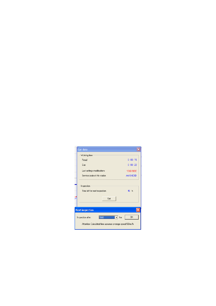
2.5.4 Service
Shows the amount of time that controller has been driving on petrol/gas. Makes possible to set time
remaining to the next system inspection. Exceeding that time will be signalized by beeping of the
buzzer and switch LED's blinking after each turning on the controller in Auto mode until next
system inspection will be set by the installer.
All service numbers of the PCs connected to the ECU and changing its settings will be written in its
memory. This feature makes possible to detect easily interference of PC other than used by service.
16
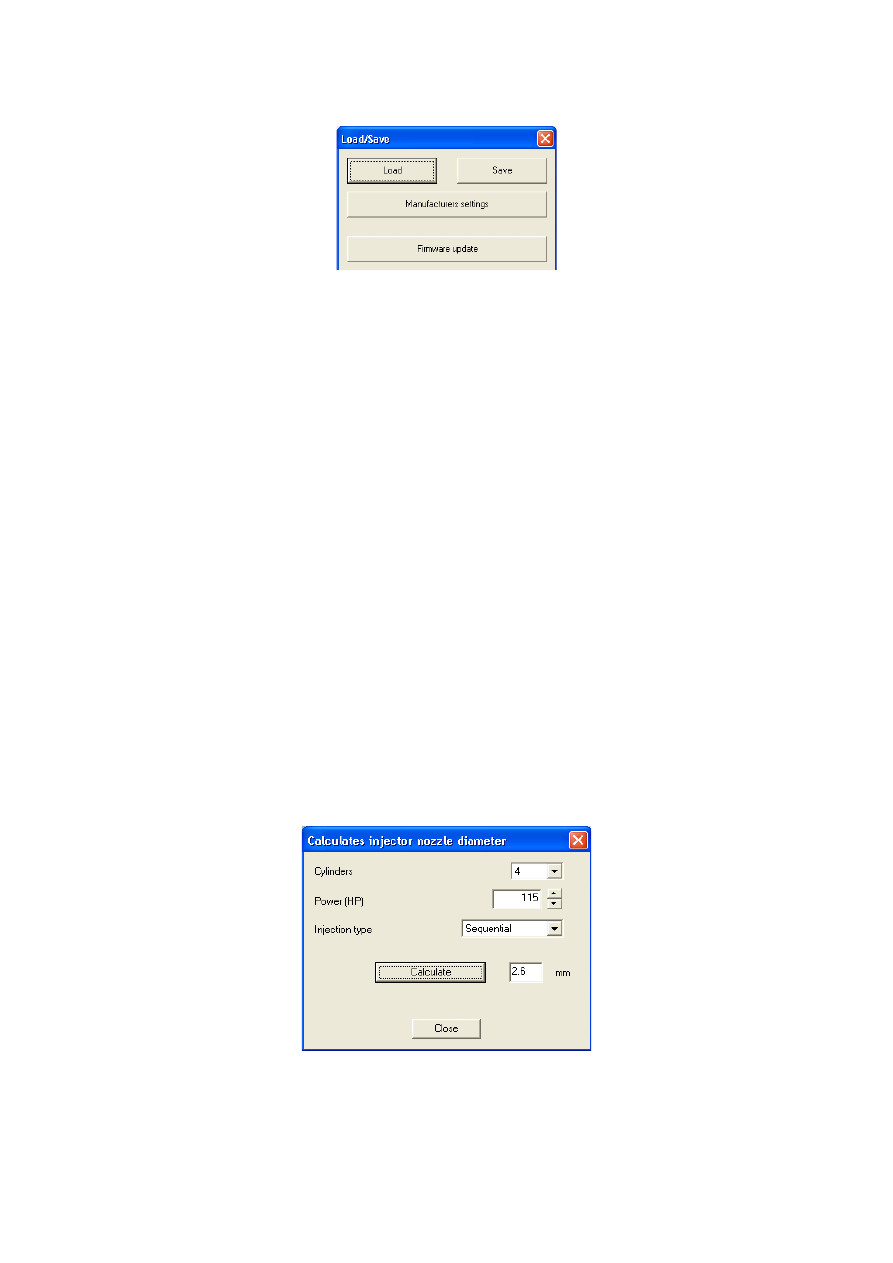
2.5.5 Load/Save
Makes possible to “Save” current program settings in a *.xset file. All the settings like the
multiplier values, sensor types etc. can be saved on disk and easily restored in any moment by
pressing the “Load” button. In any moment we can restore original values of the controller by
pressing the „Manufacturers settings” button. It is also possible to update the controller's firmware.
2.5.6 Languages
There are following software interface languages available to choose from:
●
Polish
●
English
●
Russian
●
German
●
Turkish
●
Czech
●
Slovakian
●
Spanish
●
Portuguese
●
Italian
●
Lithuanian
●
Croatian
2.5.7 Calculator of injectors' nozzle diameter
This function makes possible to calculate injection nozzle's diameter according to amount of BHP
to one cylinder and injection opening strategy type.
Attention: Algorithm assumes that reducer's pressure has been set at 1 bar (for LPG reducer) or 1,8
17
bar (for CNG reducer). Calculated values are only approximate values and it is recommended
to drill the injector nozzles from a diameter smaller from calculated one by 0,2mm and
depending on the communicates during autocalibration eventually increasing it by step of 0,2mm.
2.5.8 Help
Opens directory including this manual and controller's harness wiring diagrams.
2.5.9 About us
Some information about “Europegas” Sp. z o.o. Company divisions in Poland with all addresses,
e-mails and other contact information.
3. Autocalibration
In Calibration bookmark there are three maps:
•
Multiplier's map -blue colour
•
Petrol injection opening times (on petrol) -red colour
•
Petrol injection opening times (on gas) -blue colour
Left vertical axis (Multiplier value) and bottom horizontal axis (Time) [ms] are assigned to the
multiplier map. Multiplier map is used to set the multiplier for particular injection opening time.
That function is being realized by the blue points placed on the whole map with interval of one
18

second. To move the active multiplier point (green one) it should be selected by clicking it by the
left mouse button and drag it up and down. To adjust the multiplier we can also use following keys:
← - left arrow -changes active point to previous one by 1 ms (changes active petrol injection
opening time).
→ - right arrow -changes active point to subsequent one by 1 ms (changes active injection opening
time).
↓ - bottom arrow -decreases the multiplier for particular injection opening time. In example
changing the multiplier value from 1,0 to 0,8 will cause shortening of gas injection opening time by
20%.
↑ -upper arrow -increases the multiplier for particular injection opening time. In example changing
the multiplier value from 1,0 to 1,2 will cause elongation of gas injection opening time by 20%.
„Page Up” – moves the whole multiplier line up.
„Page Down” -moves the whole multiplier line up.
Besides the multiplier map there are two other maps present in that window. Red colour points
create the map of petrol injection opening times (on petrol). Blue colour points create the map of
petrol injection opening times (on gas). Right vertical axis (vacuum) [kPa] and bottom horizontal
axis (Time) [ms] are assigned to these maps. When enough points has been collected the controller's
software draws continuous lines between these points.
On the map we can also find green marker created by two crossed lines, which position changes
depending on the collector pressure and gasoline injection times. It is very useful during collection
of the map because it shows at which load and injection time the engine works.
Buttons “Erase petrol map” “Erase gas map” are used for erasing gasoline and LPG maps.
Nearby the buttons is situated the selection field “Blockade”, which is locking the gasoline map i.e.
the controller having collected the gasoline map (when the map is drawn with a continuous line)
will not modify it in application after checking that field.
In the „Map” bookmark there is „Auto-calibration” button which You should press for starting the
autocalibration. On the bottom right side of the window a progress bar of calibration process will
appear. Prior to starting autocalibration, start the engine and wait until the lambda probe starts to
work. To start autocalibration the reducer's temperature must be at least 50 C degree.
During auto-calibration the engine should work on idle. Do not increase RPM, switch off air-
conditioning and lights, do not turn the steering wheel, because this may cause erroneous action of
the autocalibration. Please notice that during the autocalibration all other program functions remain
inactive (Only “Turn-off auto-calibration” is available in case of any problems with the engine).
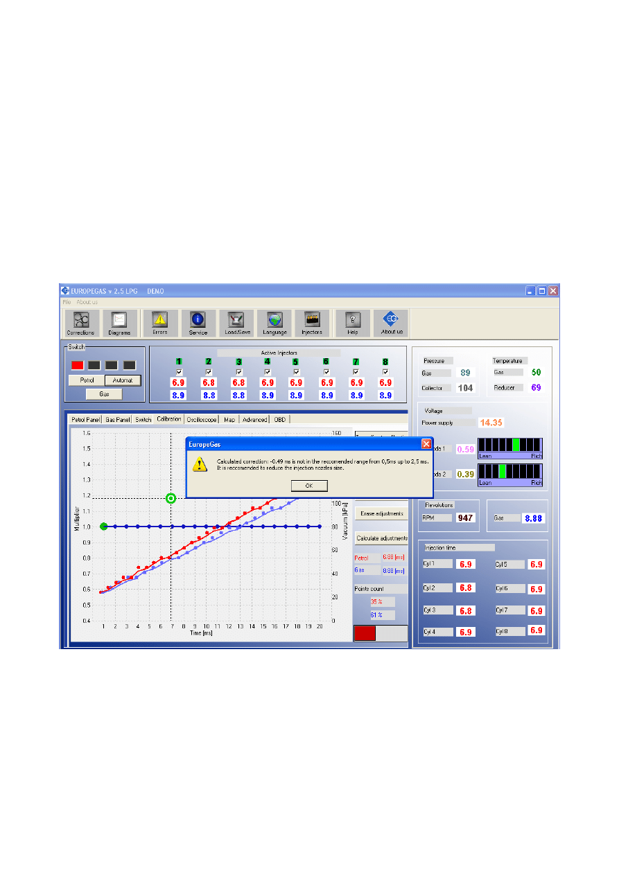
During autocalibration controller is changing over the fuel type from petrol to LPG several times in
order to calculate main time correction between petrol and gas injectors opening time. Calculated
correction is constant [ms] and it is the difference between petrol injector opening time and gas
injector opening time. If the gas pressure and injection nozzle diameter has been selected adequate
to particular car engine's power main correction should be between 0,5 [ms] and 2,5 [ms]
(recommended value is between 0,5 [ms] and 1,5 ms [ms]).
If the main correction is lower than 0,5 ms, it means that the injectors nozzle should be changed
to smaller ones or reducer's pressure should be lowered (it is not recommended to set the reducer's
pressure lower than 1 bar).
If the main correction is higher than 2,5 ms, it means that the injectors nozzle should be
changed to bigger ones or reducer's pressure should be higher.
Attention: When the injection nozzle diameter is far from the proper value, some of the cars might
stall while the car is changing over from petrol to gas during autocalibration. In this case if we want
19

to finish autocalibration to see the correction it is possible to run the autocalibration on higher revs.
To do this we need to increase the revs up to constant value (like 2500-3000 RPM) and keep it like
this till the autocalibration ends. However after checking calculated corrections we need to change
injection nozzle diameter or/and reducers pressure and run the autocalibration again.
Attention: Before running every another autocalilbration we need to set the main correction
back to 1,0 ms and use the button “Erase the adjustments” (in Calibration bookmark)
3.1 Collecting the gasoline injection map with gasoline (gasoline map)
If autocalibration has finished and calculated proper main correction we should erase petrol and
gas map so can switch over the vehicle to gasoline and drive about 15-20 minutes to collect the
gasoline map.
Attention: In case if we won't erase petrol/gas map before mapping during the drive, and the car
has worked for a long time on idle on petrol/gas, so the buffer of petrol/gas is near to 100%, we
could have problem with collecting map in whole range of injection opening time.
During collection of the map try to drive without changing gears i.e. at the 4
th
gear and in such way
so that the lambda probe “works” (changes its mode from weak to rich). During driving red points
should start appearing on the map. To collect the map quicker select vehicle load in such way so
that collect points in places, which are empty until now. Collection of maps is performed without
participation of the diagnostic program, thus can be done without PC connected. However,
while performing this action with connected computer and diagnostic program we can do it much
quicker and we see accurately, what happens to the vehicle. When the controller recognize that the
number of collected red points is sufficient, the map will be drawn with a continuous red line. The
accuracy of drawn line depends on the density of points collected in given area. The more points
will be collected in given area, the more accurate the petrol map line will be.
Attention: It is recommended to collect 100% of petrol map.
3.2 Collecting the gasoline injection map with LPG (LPG map)
Having collected the gasoline map vehicle can be switched to LPG so we can start to collect the
LPG map. The LPG map should be collected in the same road conditions and with similar loads as
the gasoline map. The LPG map is drawn with blue points. Having collected sufficient number of
points the map will be drawn with a continuous blue line. The accuracy of drawn line depends on
the density of points collected in given area. We can say that the LPG map has been collected with
enough accuracy when there won't be narrow curves in its horizontal axis. The more points will be
collected in given area, the more accurate the gas map line will be.
Attention: After making any changes to multiplier line it is recommended to erase the gas map
and collect in again
. In this way we can update the map quicker on in the application (especially
when the percentage of gas map buffer is near to 100%)
20
3.3 Making correction to map by using multiplier. Calculating the corrections.
If the injectors nozzle diameter and reducers pressure has been selected properly (which will be
confirmed by proper main correction calculated during autocalibration) the petrol and gas map
should agree. In case if there are big differences between both lines we can use “Calculate
adjustments” option. Gas injectors opening time will be automatically corrected where the distance
between both maps (for the same petrol injection opening time) will be too big.
After saving the calculated adjustments into controllers memory we could erase gas map and collect
it again. Both maps should agree from now on.
During collection of gas map with PC connected we can adjust the multiplier adjustments manually
in the places where we see that blue line is not agreeing with red one.
3.4 Setting multiplier's corrections manually
The controller can be also set manually. We start the setting of the controller – as for the previous
method – with autocalibration (it is indispensable for correct operation of the controller, see point
3). Then, if the autocalibration has been finished successfully and correction values for the gas
injectors are correct, we switch over the vehicle to gasoline and drive it for the test. The setting of
the multiplier characteristic should be performed as follows:
We drive the vehicle using gasoline, we make efforts to keep the constant engine load i.e. gasoline
injection times should be stable. We match the load so that the gasoline injection time was i.e. about
5 [ms]. Evaluation of gasoline injection times will be easier with help of the green marker, which
21

vertical position at the horizontal axis depends on injection time. Now we switch over the vehicle to
LPG and watch, if the green marker will not change its position at the injection time axis i.e. the
gasoline injection time has not changed. If the gasoline injection time became shorter (the marker
has shifted to the left), this means that for given gasoline injection times the multiplier is to high
(the mixture is too rich). In such case correct the multiplier – in our case for the time 5 [ms] -
downwards. If after changeover from gasoline to LPG the marker goes to the right, this means that
the mixture is too weak and the multiplier map should be shifted upwards for given injection times.
The procedure described above should be performed for a few injection times beginning from the
calibration point as far as to injection times for great load. We can check the multiplier map with
leap of every 2 [ms] starting from idle revs injection opening time point.
After execution of described manual setting both maps – gasoline and LPG – should agree.
3.5. LED switchboard
The LED switchboard consists of:
●
LED line indicating gas level
●
button for changeover between both fuels. Push to change between petrol and gas (Auto
mode)
LED line– shows current LPG level in the tank. 3 green LEDs indicate a full tank; a red LED
indicates “reserve”.
The LED – shows current operating status:
●
off – the engine runs on gasoline
●
slow blinking (once per second) – Controller is in Auto mode and when the temperature of
reducer is lower than 50 C degree, it's awaiting for reducer to reach minimal temperature set
in the Switch Panel. If reducer temperature has reached temperature of 50 C degree, if the
required RPM level was reached, from that moment after 5 seconds solenoid valves are
going to be opened, and after another 5 seconds the gas injectors are going to be opened.
●
Fast blinking (twice per second) – If reducer's temperature is lower than 50 C degree, after
reaching required reducer's temperature (set in Switch Panel), controller waits with
changeover until required time amount will pass (set in Time parameter from Switch Panel).
If reducer's temperature is lower than 50 C degree, controller will wait additionally for the
time required for preheating gas injectors (if option has been turned on in Advanced Panel).
After that total amount of time, if the proper RMP level (set in Switch Panel) has been
reached the controller will changeover to gas.
Attention: If buzzer signal has been activated fast blinking means controller error
(changeover to petrol due to low gas level in the tank)
●
on – the engine runs on gas
The controller “remembers” the last fuel type setting before switching the ignition switch off.
In order to start the engine on LPG (e.g. when the gasoline pump is damaged), press in and
hold the button on the LED switchboard while turning the ignition on. The LED should come
on. When the engine revolutions are detected, the controller turns the solenoid valves on and
the engine starts on LPG. In this mode, it is not possible to turn back to gasoline. Turn the
ignition off to turn this special mode off.
22
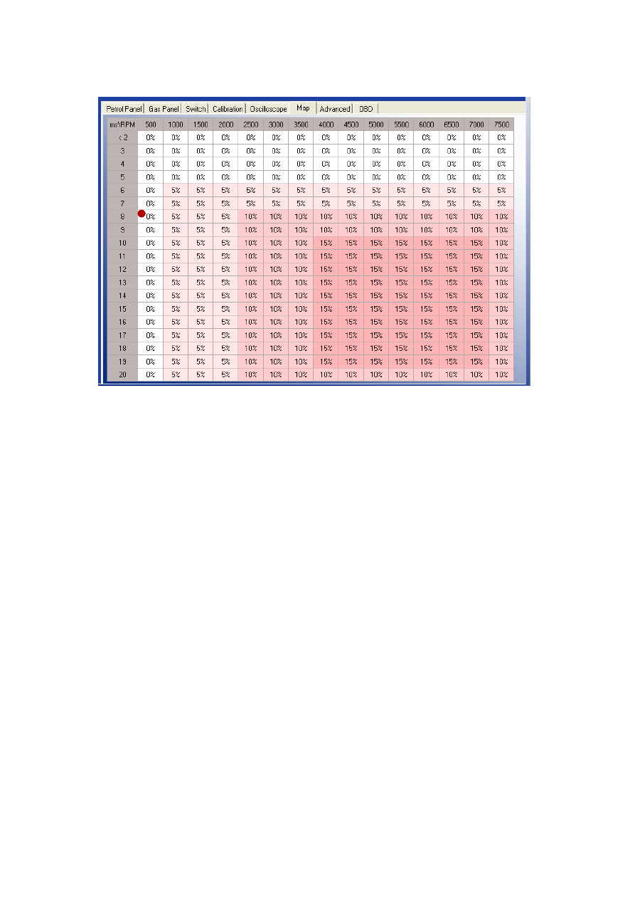
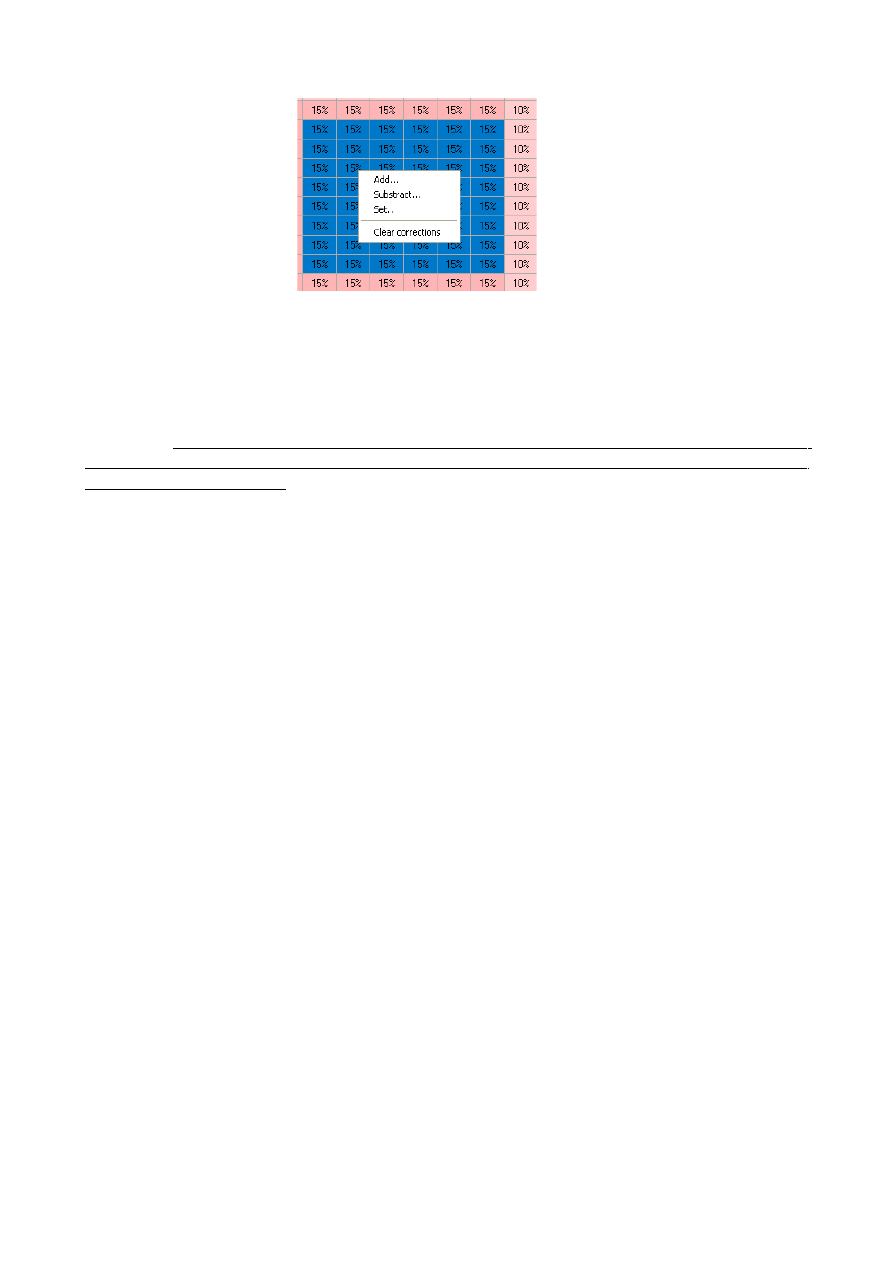
4. Injection map correction depending on engine's RPM
OSCAR-N OBD CAN controller makes possible to adjust the composition of air/fuel mixture in the
whole range of engine load. To do this we can use Corrections map placed in the “Map” bookmark
(feature protected by password).
On the picture above we can see map of corrections for petrol injection opening time depending on
RPM level. In the screenshot above the opening time of gas injectors has been elongated by 15% in
range of high revs. Thanks to that map we can adjust mixture by shortening or elongating the gas
injectors opening time in range from –50% up to +50%.
Editing of the map cells can be done in following way:
1) With right mouse button we mark the area in which we would like to enter the percentage
correction of gas injectors opening time.
2) With left mouse button we click on any of cells marked by us.
3) Pop-up menu will show up, with following options:
a) “Add” -adds value written from keyboard to all the cells selected.
b) “Subtract” -subtracts value written from the keyboard from all the cells selected.
c) “Set” -sets the value written from the keyboard to all the cells selected.
d) “Clear corrections” -sets the 0 value to all the cells selected.
23
After selecting the area on the map it is possible to modify it with usage of Page Up and Page
Down keys.
Page Up – increase value by 1%
Page Down – decrease value by 1%
Attention: Main time correction [ms], correction of the multiplier [%] (from Calibration
bookmark) and correction from RPM [%] (from Map bookmark) summed together give total
gas injectors opening time
24
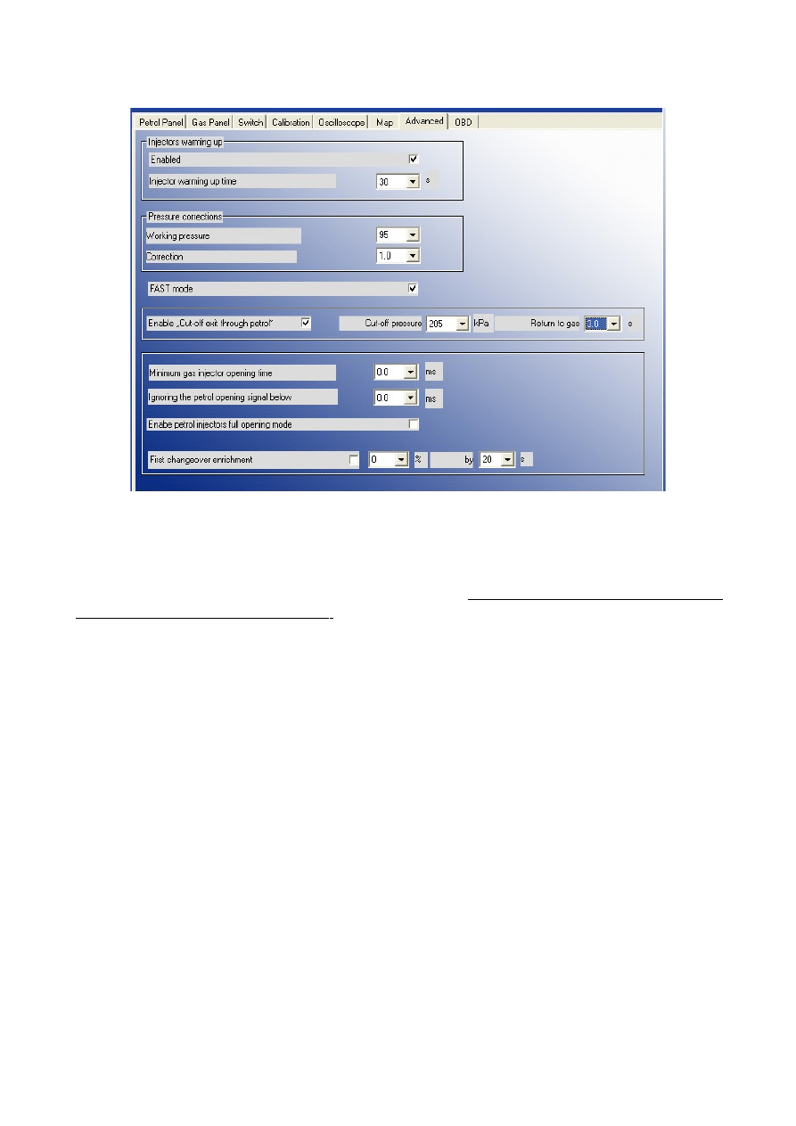
5. Advanced settings
In Advanced bookmark we can find following features (protected by password)
1) “Injectors warming up” -After enabling that options we can set period of time for which the gas
injectors coils should be preheated by single pulses from ECU (properly shortened so they won't
cause opening of injector) before first changeover to gas (function works only if the reducer
temperature is less than 50 C degree)
. The length of pulse is being set automatically depending on
the type of selected injector from injection rail in Gas Panel.
2) “Pressure corrections” -options which makes possible making following correction depending
on value of differential pressure:
•
“Working pressure” -gas pressure at the gas injectors during autocalibration, during work on idle.
Default set at 100 kPa (and reducer should be set at this value before running autocalibration).
•
“Correction” -Describes how the mixture should be enriched (by elongating the injectors opening
times) when the pressure at the injector rail will start falling (to compensate the mixture
impoverishment).
Examples:
a)Working pressure -100kPa, Correction -1 → during change of pressure down to 90kPa, times of
gas injection will be elongated by 10%
b)Working pressure -100kPa, Correction -0.2 → during change of pressure down to 90kPa, times of
gas injection will be elongated by 2%
a)Working pressure -100kPa, Correction -1 → during change of pressure down to 95kPa, times of
gas injection will be elongated by 5%
a)Working pressure -100kPa, Correction -0.2 → during change of pressure down to 95kPa, times of
gas injection will be elongated by 1%
If the injector nozzle's diameter has been selected properly the default correction value is 1.
3) “Fast mode” -enabling this feature reduces the time of changeover to gas in “Auto mode” from
25

10 down to 3 seconds.
4) “Enable “Cut-off exit throught petrol” -this feature might be especially usefeul when installed
reducer(s) are making very high pressure at the outlet during cut-off conditions. If the reducer's gas
pressure (differential) will exceed value given in the field “Cut-off pressure” the controller closes
the gas injectors and turnover back to petrol. After the amount of time [s] given in field “Return to
gas” the controller is going back to “Auto mode”.
5) “Minimum gas injector opening time” -this parameter set minimum time of the LPG injectors
opening time. Might be used when the short petrol injection opening times, the times of LPG
injection opening time are close to minimum value of LPG injectors opening time, which may
cause engine stalling (in example: during exit from cut-off). In example: when we set this parameter
at 3,1 ms, if the controller has calculated gas injector opening time less than 3,1 ms (like 2,8 ms) its
opening time will be not less than 3,1 ms.
Attention: For VALTEK type injectors the parameter shouldn't be higher than 3,8 [s].
6) “Ignoring the petrol opening below” -this parameter sets the minimum value of petrol injectors
opening time which will be moved onto LPG injectors. This option should be enabled when petrol
injection controller generates very short pulses on petrol injectors (from 0,3 [ms] up to 1 [ms]),
which normally doesn't cause dosage of fuel but after summing with all the corrections (main
correction, multiplier correction and map correction) might cause unnecessary gas injection (partial
cut-off). Default value “0” means that every pulse from petrol injector will be moved onto LPG
injectors.
Attention:Maximum value of this parameter is “1,9” [ms].
7) “Enable petrol injectors full opening mode” -this option should be enabled only with cars where
the injectors during high revs are fully opened. This can cause engine stalling during drive on gas.
These happens mainly to tuned cars.
8) “First changeover enrichment” -After activating that feature it is possible to enrich the mixture
once after first changeover from petrol to gas. After first changeover the gas injection opening time
will be elongated by selected value (in %). During desired time period (in sec.)the enrichment will
be decreasing linearly downto 0%. For an example after setting the enrichment to 20% for 20 sec.
Period, after 10 sec. From changeover enrichment value will be 10%, after 15 sec. It will be 5%
and after 20 sec. 0%.
26
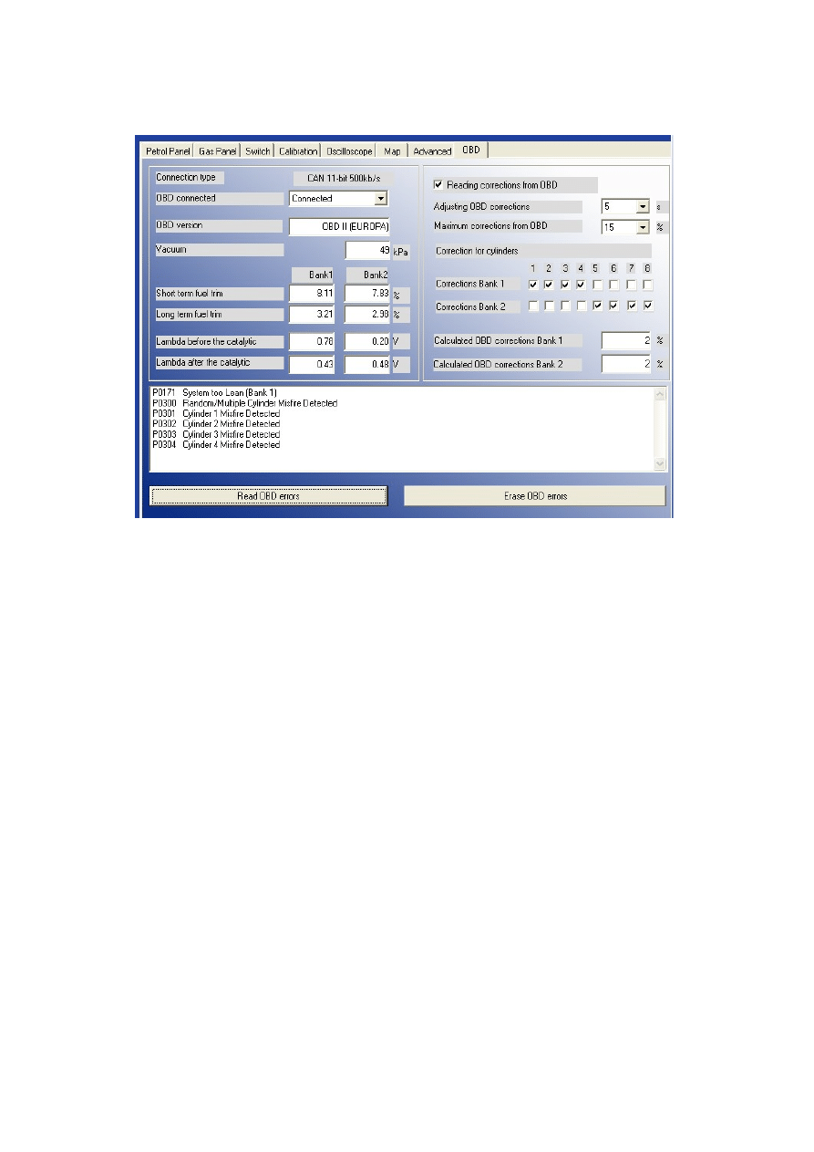
6. Reading OBD correction using CAN bus
In OSCAR-N OBD CAN controller it is possible to connect directly to CAN bus and to read actual
car's OBD work parameters and errors. To use this feature it is necessary to connect to the car's
OBD connector with CAN Low i CAN High wires from harness of OSCAR-N OBD CAN
controller.
After connecting to OBD CAN bus and turning on the option “OBD connected” we can watch
selected parameters in application.
After clicking the button “Read OBD errors” it is possible to read the OBD errors written in
original car's petrol controller. We can erase these errors from its memory by pressing button
“Erase OBD errors”.
By enabling option “Reading corrections from OBD” we have possibility of correcting gas
injectors opening time according to actual readings of “Short Term Fuel Trim” and “Long Term
Fuel Trim”. The time interval of reading the corrections can be set in parameter “Adjusting OBD
corrections”. Thanks to above feature the work of gas injection controller is self-adapting itself to
car's original OBD in real time. If elements rest of sequential gas injection system has been chosen
and installed properly it makes possible to eliminate MIL (“check engine” light) during drive on
gas. To fulfill the emission norms used by manufacturers of most modern cars it is necessary to use
injectors of highest precision of gas dosing and reducers with power adequate to particular car
engine's BHP.
Attention: Feature “Reading corrections from OBD” might be used only in cars which are having
OBD on CAN bus, because only this type of data bus is capable to ensure proper communication
quality with the controller. Another condition needed to fulfill for this feature to work is the fact of
previously making autocalibration on idle, and making corrections to the multiplier properly.
Recommended value for “Adjusting the ODB corrections” parameters is 5 seconds. This parameter
27

sets the time interval after which the averaged value of Long Time Fuel Trim is being read.
Parameter “Maximum correction from OBD” shouldn't be bigger than 15%. This parameter sets
the maximum value of Long Time Fuel Trim which gas controller will try to adjust by changing gas
injection opening time. In example, when this parameter will be 15% and the LTFT value will be
±
25%, the OSCAR-N OBD CAN controller will be trying to adjust the injection opening time just
like for the
±
15% value.
OSCAR-N OBD CAN controller reads the value of mixture correctors from OBD and sets the
amount of gas injected so the „Short Time Fuel Trim” (STFT) i „Long Time Fuel Trim” (LTFT)
will be oscillating as close to expected car's manufacturers default values as possible.
STFT and LTFT mixture correctors are referring to the corrections dynamically imported to table of
injection opening times in original petrol ECU. These corrections are being made all the time to
obtain the ideal proportions of stechiometric value of air/fuel mixture (14,7 : 1). STFT are referring
to temporary conditions of driving (like accelerating, braking etc.). LTFT are referring to long
lasting conditions (like work the engine on idle) and they are being an averaged value from STFT.
Corrections are showed up as a percentage. Positive value means that in that particular moment the
mixture is too lean and petrol ECU is trying to elongate the petrol injectors opening time to enrich
it. Negative value means that mixture is too reach and petrol ECU is trying to shorten the injection
opening time to make it leaner.
The concept of banks is referring to “V” type engines. Cylinder marked as no. 1 should be always in
bank no. 1. “V” type engines should always have one side assigned to bank no. 1 (cylinders with
numbers from 1 to 3 or from 1 to 4) and another side to bank no. 2 (cylinders with numbers from 4
to 6 or from 5 to 8). Straight type engines should have all the cylinders assigned to bank no. 1.
Algorithm of controller's adaptation in dependency of OBD corrections is basing on reading actual
values of STFT and LTFT and depending on these values elongating or shortening gas injection
opening times. In result of such actions mixture is being enriched or leaned to keep the STFT and
LTFT in desired range.
In example: if LTFT are going too far in positive direction (they are growing), algorithm is
increasing the gas injection opening time to enrich the mixture, so finally the LTFT are going in
negative direction (they are falling).
If the LTFT are going to far in negative direction (they are falling), algorithm is shortening the gas
injection opening time to lean the mixture, so finally the LTFT are going in positive direction (they
are growing).
Acutal value of calculated corrections we should control from time to time. To big absolute value of
these correction mean that some mechanical part might be worn out and we should make some
mechanical adjustments to some parts of sequential gas injection system.
28

6.1 OBD connector's description
Pin 4 - GND
Pin 5 - GND
Pin 6 - CAN High (J-2284)
Pin 14 - CAN Low (J-2284)
Pin 16 - +12V
If the car has OBD on the CAN bus then on pins no. 6 and no. 14 should be +2.5V voltage
regarding the GND.
OBD system on CAN bus has been introduced in United States. At the beginning it was installed
only in some cars manufactured after year 2003. From year 2008 it is obligatory for all the vehicles
manufactured on US market. In European cars there is no such requirement yet (beginning of year
2008) and from the cars being sold on European market only vehicles manufactured by Japanese
and Korean concerns have the OBD on CAN bus.
29
Wyszukiwarka
Podobne podstrony:
Instruction of connection and programming of OSCAR N MINI controller
Instrukcja podlaczenia i programowania OSCAR N PLUS OBDCAN PL
Possible Effects of Strategy Instruction on L1 and L2 Reading
The life and works of Oscar Wilde
Assignment of connectors and sockets
integration and radiality measuring the extent of an individuals connectedness and reachability in a
The comparison of two differnt translation of Oscar Wilde
Instruction of burn loader by J Tag,3 13
The using document instructions of Device Manage(1)
Cordwainer Smith The complete Instrumentality of Mankind
Przykładowy program instruktażu stanowiskowego operatora żurawia, program szkol
Instrukcja obslugi Connectify, informatyka
Ada 95 A guide for C and C programmers S Johnston
Embedded Systems Building and Programming Embedded Devices
BIBLIOGRAPHY #5 Cyril of Alexandria & the Christological Controversy
Microwave irradiation of hazelnuts for the control of aflatoxin producing Aspergillus parasiticus
Instrukcja wgrywania softu z użyciem programu DeepBurner
How to Design Programs An Introduction to Computing and Programming Matthias Felleisen
więcej podobnych podstron