
C2833x/C2823x C/C++ Header Files and Peripheral Examples Quick Start
Version 1.31
August 4, 2009
1
C2833x/C2823x C/C++ Header Files and Peripheral
Examples Quick Start
1
Device Support:............................................................................................................................ 2
2
Introduction: ................................................................................................................................. 2
2.1
Revision History...................................................................................................................... 3
2.2
Where Files are Located (Directory Structure) ........................................................................ 4
3
Understanding The Peripheral Bit-Field Structure Approach ................................................... 5
4
Peripheral Example Projects ....................................................................................................... 6
4.1
Getting Started ....................................................................................................................... 6
4.1.1
Getting Started in Code Composer Studio v3.x ........................................................... 6
4.1.2
Getting Started in Code Composer Studio v4............................................................ 10
4.2
Example Program Structure.................................................................................................. 15
4.2.1
Source Code ............................................................................................................. 16
4.2.2
Linker Command Files .............................................................................................. 16
4.3
Example Program Flow......................................................................................................... 18
4.4
Included Examples: .............................................................................................................. 19
4.5
Executing the Examples From Flash..................................................................................... 21
4.6
Converting Floating-Point Compiled Examples to Fixed-Point and Vice Versa ..................... 24
5
Steps for Incorporating the Header Files and Sample Code ................................................... 31
5.1
Before you begin................................................................................................................... 31
5.2
Including the DSP2833x Peripheral Header Files ................................................................. 31
5.3
Including Common Example Code........................................................................................ 36
6
Troubleshooting Tips & Frequently Asked Questions............................................................. 39
6.1
Effects of read-modify-write instructions. .............................................................................. 41
6.1.1
Registers with multiple flag bits in which writing a 1 clears that flag........................... 42
6.1.2
Registers with Volatile Bits. ....................................................................................... 42
7
Migration Tips for moving from the TMS320x280x or TMS320x281x header files to the
TMS320x2833x/TMS320x2823x header files ............................................................................. 43
8
Packet Contents: ........................................................................................................................ 46
8.1
Header File Support – DSP2833x_headers .......................................................................... 46
8.1.1
DSP2833x Header Files – Main Files........................................................................ 46
8.1.2
DSP2833x Header Files – Peripheral Bit-Field and Register Structure Definition
Files .......................................................................................................................... 47
8.1.3
Code Composer .gel Files......................................................................................... 48
8.1.4
Variable Names and Data Sections........................................................................... 48
8.2
Common Example Code – DSP2833x_common................................................................... 50
8.2.1
Peripheral Interrupt Expansion (PIE) Block Support .................................................. 50
8.2.2
Peripheral Specific Files............................................................................................ 51
8.2.3
Utility Function Source Files...................................................................................... 52
8.2.4
Example Linker .cmd files ......................................................................................... 52
8.2.5
Example Library .lib Files .......................................................................................... 53
9
Migrating Projects from Code Composer Studio v3.x to Code Composer Studio 4.0 ........... 53
10
Detailed Revision History: ......................................................................................................... 54

V1.30 Quick Start Readme
2
1 Device Support:
This software package supports 2833x and 2823x devices. This includes the following:
TMS320F28335, TMS320F28334, TMS320F28332, TMS320F28235, TMS320F28234, and
TMS320F28232.
Throughout this document, TMS320F28335, TMS320F28334, TMS320F28332,
TMS320F28235, TMS320F28234, and TMS320F28232 are abbreviated as F28335, F28334
F28332, F28235, F28234, and F28232 respectively.
2 Introduction:
The C2833x/C2823x C/C++ peripheral header files and example projects facilitate writing in
C/C++ Code for the Texas Instruments TMS320x2833x DSPs. The code can be used as a
learning tool or as the basis for a development platform depending on the current needs of
the user.
•
Learning Tool:
This download includes several example Code Composer Studio™
†
projects for a
‘2833x/’2823x development platform. One such platform is the eZdsp™
††
F28335 USB
from Spectrum Digital Inc. (www.spectrumdigital.com). Another such platform is the
“Delfino” F28335 Control Card from Texas Instruments (www.ti.com/f28xkits)
These examples demonstrate the steps required to initialize the device and utilize the on-
chip peripherals. The provided examples can be copied and modified giving the user a
platform to quickly experiment with different peripheral configurations.
These projects can also be migrated to other devices by simply changing the memory
allocation in the linker command file.
•
Development Platform:
The peripheral header files can easily be incorporated into a new or existing project to
provide a platform for accessing the on-chip peripherals using C or C++ code. In
addition, the user can pick and choose functions from the provided code samples as
needed and discard the rest.
To get started this document provides the following information:
•
Overview of the bit-field structure approach used in the C2833x/C2823x C/C++
peripheral header files.
•
Overview of the included peripheral example projects.
•
Steps for integrating the peripheral header files into a new or existing project.
•
Troubleshooting tips and frequently asked questions.
†
Code Composer Studio is a trademark of Texas Instruments (www.ti.com).
††
eZdsp is a trademark of Spectrum Digital Inc (www.spectrumdigital.com).
Trademarks are the property of their respective owners.

V1.20 Quick Start Readme
3
•
Migration tips for users moving from the DSP281x and DSP280x header files to the
DSP2833x/2823x header files.
Finally, this document does not provide a tutorial on writing C code, using Code Composer
Studio, or the C28x Compiler and Assembler. It is assumed that the reader already has a
28335 hardware platform setup and connected to a host with Code Composer Studio
installed. The user should have a basic understanding of how to use Code Composer Studio
to download code through JTAG and perform basic debug operations.
2.1 Revision History
Version 1.31
This version makes a minor update to remove Tool="DspBiosBuilder" from all PJT
files to ease migration of CCSv3.3 to CCSv4 projects on the Microcontroller-only
(code-size limited) version of CCSv4. A detailed revision history can be found in
Section 10.
Version 1.30
This version includes minor corrections and comment fixes to the header files and
examples, and also adds separate example folders, DSP2833x_examples_ccsv4, and
DSP2823x_ccsv4, with examples supported by the Eclipse-based Code Composer
Studio v4. A detailed revision history can be found in Section 10.
Version 1.20
This version includes minor corrections and typo fixes to the header files and
examples, and adds the DSP28x_Project.h file, found in the /common/include/
directory, which allows easy porting of project files and examples between device
header files. Support has also been added for access to dual-mapped EPWM
registers. A detailed revision history can be found in Section 10.
Version 1.10
This version includes minor corrections to the header and common files, and adds
support for F2823x non-floating point unit examples. These examples use the same
common and header files as the F2833x examples. A detailed revision history can be
found in Section 10.
Version 1.03
This version includes minor additions to the header and common files, including an
upgraded revision to the SFO library V5. A detailed revision history can be found in
Section 10.
Version 1.02
This version includes minor additions to the gel files and updates to the
source/example files. A detailed revision history can be found in Section 10.
Version 1.01
V1.30 Quick Start Readme
4
This version fixes some typos and minor errors in the DSP2833x header files and
examples. A detailed revision history can be found in Section 10.
Version 1
This version is the first release of the DSP2833x header files and examples.
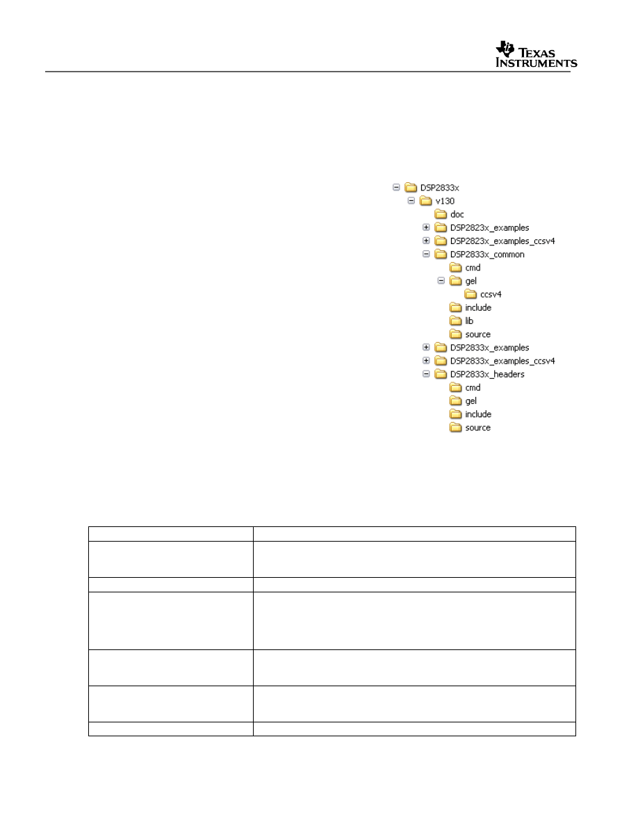
2.2 Where Files are Located (Directory Structure)
As installed, the C2833x/C2823x C/C++ Header Files
and Peripheral Examples is partitioned into a well-
defined directory structure. By default, the source code
is installed into the c:\tidcs\c28\DSP2833x\<version>
directory.
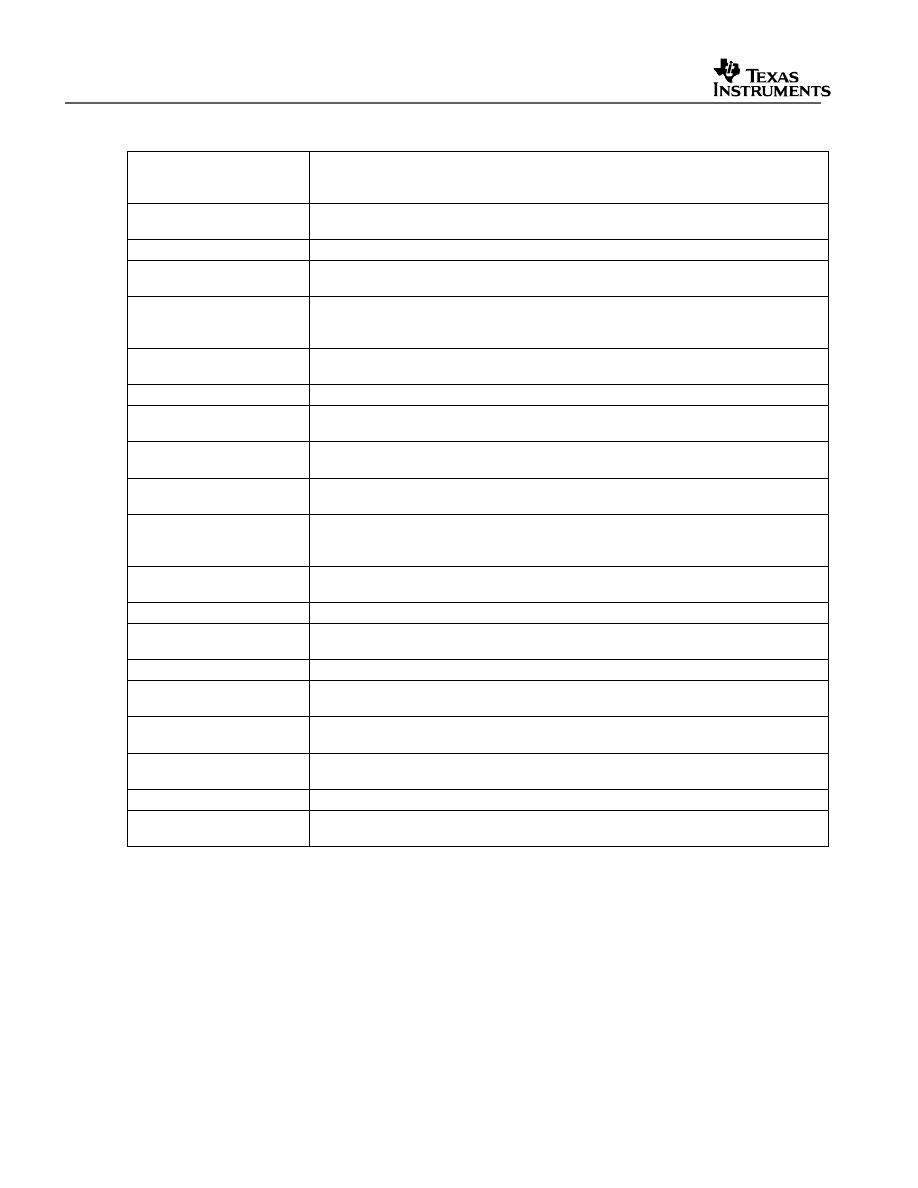
Table 1 describes the contents of the main directories
used by DSP2833x/2823x header files and peripheral
examples:
Table 1.
DSP2833x Main Directory Structure
Directory
Description
<base>
Base install directory. By default this is c:\tidcs\c28\DSP2833x\<version>.
For the rest of this document <base> will be omitted from the directory
names.
<base>\doc
Documentation including the revision history from the previous release.
<base>\DSP2833x_headers
Files required to incorporate the peripheral header files into a project .
The header files use the bit-field structure approach described in Section
3.
Integrating the header files into a new or existing project is described in
Section 5.
<base>DSP2833x_common
Common source files shared across example projects to illustrate how to
perform tasks using header file approach. Use of these files is optional,
but may be useful in new projects. A list of these files is in Section 8.
<base>\DSP2833x_examples
Example Code Composer Studio projects compiled with floating point unit
enabled. These example projects illustrate how to configure many of the
on-chip peripherals. An overview of the examples is given in Section 4.
<base>\DSP2823x_examples
Example Code Composer Studio projects compiled with floating point unit
V1.20 Quick Start Readme
5
disabled. These example projects illustrate how to configure many of the
on-chip peripherals. An overview of the examples is given in Section 4.
<base>\DSP2833x_examples_ccsv4 Example Code Composer Studio v4 projects compiled with floating point
unit enabled. These example are identical to those in the
\DSP2833x_examples directory, but are generated for CCSv4 and cannot
be run in CCSv3.x. An overview of the examples is given in Section 4.
<base>\DSP2823x_examples_ccsv4 Example Code Composer Studio projects compiled with floating point unit
disabled. These example are identical to those in the
\DSP2833x_examples directory, but are generated for CCSv4 and cannot
be run in CCSv3.x. An overview of the examples is given in Section 4.
Under the DSP2833x_headers and DSP2833x_common directories the source files are
further broken down into sub-directories each indicating the type of file. Table 2 lists the sub-
directories and describes the types of files found within each:
Table 2.
DSP2833x Sub-Directory Structure
Sub-Directory
Description
DSP2833x_headers\cmd
Linker command files that allocate the bit-field structures described in Section 3.
DSP2833x_headers\source
Source files required to incorporate the header files into a new or existing
project.
DSP2833x_headers\include
Header files for each of the on-chip peripherals.
DSP2833x_common\cmd
Example memory command files that allocate memory on the devices.
DSP2833x_common\include
Common .h files that are used by the peripheral examples.
DSP2833x_common\source
Common .c files that are used by the peripheral examples.
DSP2833x_common\lib
Common library (.lib) files that are used by the peripheral examples.
DSP2833x_common\gel
Code Composer Studio v3.x GEL files for each device. These are optional.
DSP2833x_common\gel\ccsv4 Code Composer Studio v4.x GEL files for each device. These are optional.
3 Understanding The Peripheral Bit-Field Structure Approach
The following application note includes useful information regarding the bit-field peripheral
structure approach used by the header files and examples.
This method is compared to traditional #define macros and topics of code efficiency and
special case registers are also addressed. The information in this application note is
important to understand the impact using bit fields can have on your application code.
Programming TMS320x28xx and 28xxx Peripherals in C/C++ (SPRAA85)

V1.30 Quick Start Readme
6
4 Peripheral Example Projects
This section describes how to get started with and configure the peripheral examples
included in the C2833x/C2823x Header Files and Peripheral Examples software package.
NOTE:
Because the ‘2833x devices are floating-point devices, the ‘2833x
peripheral examples are configured for floating-point by default.
Therefore, Code Composer Studio V3.3+ with C2000 CodeGenTools
V5.x, which includes fpu32 floating-point support, is required to build
and run these examples. To run these examples on Code Composer
3.1 and earlier, they must be re-configured for fixed-point (For more
information, see Section 4.6).
Because the ‘2823x devices are fixed-point devices, the ‘2823x
peripheral examples are configured for non-floating-point by default.
These examples run as-is on Code Composer 3.3 and earlier.
4.1 Getting Started
4.1.1 Getting Started in Code Composer Studio v3.x
To get started, follow these steps to load the 32-bit CPU-Timer example. Other examples are
set-up in a similar manner.
1. Have a hardware platform, such as the eZdsp F28335 USB, connected to a host with
Code Composer Studio installed.
NOTE: As supplied, the ‘2833x and ‘2823x example projects are built for the
‘28335/’28235 device. If you are using another 2833x or 2823x device, the memory
definition in the linker command file (.cmd) will need to be changed and the project
rebuilt.
2. Load the example’s GEL file (.gel) or Project file (.pjt).
Each example includes a Code Composer Studio GEL file to help automate loading of
the project, compiling of the code and populating of the watch window. Alternatively, the
project file itself (.pjt) can be loaded instead of using the included GEL file.
To load the ‘2833x CPU-Timer example’s GEL file follow these steps:
a. In Code Composer Studio v 3.x: File->Load GEL
b. Browse to the CPU Timer example directory: DSP2833x_examples\cpu_timer (or
DSP2823x_examples\cpu_timer)
c. Select Example_2833xCpuTimer.gel (or Example_2823xCpuTimer.gel) and click on
open.
d. From the Code Composer GEL pull-down menu select

V1.20 Quick Start Readme
7
DSP2833x CpuTimerExample-> Load_and_Build_Project (for ‘2833x devices)
DSP2823x CpuTimerExample-> Load_and_Build_Project (for ‘2823x devices)
This will load the project and build compile the project.
3. Edit DSP28_Device.h
Edit the DSP2833x_Device.h file and make sure the appropriate device is selected. By
default the 28335 is selected. For ‘2823x devices, the ‘2833x counterpart is selected.
For instance, if using F28235, DSP28_28335 is selected as the TARGET.
/********************************************************************
* DSP2833x_headers\include\DSP2833x_Device.h
********************************************************************/
#define TARGET 1
//---------------------------------------------------------------------------
// User To Select Target Device:
#define DSP28_28335 TARGET
#define DSP28_28334 0
#define DSP28_28332 0
4. Edit DSP2833x_Examples.h
Edit DSP2833x_Examples.h and specify the clock rate, the PLL control register value
(PLLCR and DIVSEL). These values will be used by the examples to initialize the
PLLCR register and DIVSEL bits.
The default values will result in a 150Mhz SYSCLKOUT frequency.

V1.30 Quick Start Readme
8
/********************************************************************
* DSP2833x_common\include\DSP2833x_Examples.h
********************************************************************/
/*-----------------------------------------------------------------------------
Specify the PLL control register (PLLCR) and divide select (DIVSEL) value.
-----------------------------------------------------------------------------*/
//#define DSP28_DIVSEL 0 // Enable /4 for SYSCLKOUT(default at reset)
//#define DSP28_DIVSEL 1 // Disable /4 for SYSCKOUT
#define DSP28_DIVSEL 2 // Enable /2 for SYSCLKOUT
//#define DSP28_DIVSEL 3 // Enable /1 for SYSCLKOUT
#define DSP28_PLLCR 10
//#define DSP28_PLLCR 9
//#define DSP28_PLLCR 8
//#define DSP28_PLLCR 7
//#define DSP28_PLLCR 6
//#define DSP28_PLLCR 5
//#define DSP28_PLLCR 4
//#define DSP28_PLLCR 3
//#define DSP28_PLLCR 2
//#define DSP28_PLLCR 1
//#define DSP28_PLLCR 0 // (Default at reset) PLL is bypassed in this mode
//----------------------------------------------------------------------------
In DSP2833x_Examples.h, also specify the SYSCLKOUT rate. This value is used to
scale a delay loop used by the examples. The default value is for a 150 Mhz
SYSCLKOUT. If you have a 100 MHz device you will need to adjust these settings
accordingly.
/********************************************************************
* DSP2833x_common\include\DSP2833x_Examples.h
********************************************************************/
……
#define CPU_RATE 6.667L // for a 150MHz CPU clock speed (SYSCLKOUT)
//#define CPU_RATE 7.143L // for a 140MHz CPU clock speed (SYSCLKOUT)
//#define CPU_RATE 8.333L // for a 120MHz CPU clock speed (SYSCLKOUT)
……
In DSP2833x_Examples.h also specify the maximum SYSCLKOUT frequency
(150MHz or 100MHz) by setting it to 1 and the other to 0. This value is used by those
examples with timing dependent code (i.e. baud rates or other timing parameters) to
determine whether 150MHz code or 100MHz code should be run.
The default value is for 150Mhz SYSCLKOUT. If you have a 100MHz device you will
need to adjust these settings accordingly. If you intend to run examples which use
these definitions at a different frequency, then the timing parameters in those examples
must be directly modified accordingly regardless of the setting here.
/********************************************************************
* DSP2833x_common\include\DSP2833x_Examples.h
********************************************************************/
V1.20 Quick Start Readme
9
……
#define CPU_FRQ_100MHZ 0 // 100 MHz CPU Freq - 1 for 100 MHz devices
#define CPU_FRQ_150MHZ 1 // 150 Mhz CPU Freq - default, 1 for 150 MHz devices
//----------------------------------------------------------------------------
5. Review the comments at the top of the main source file:
Example_2833xCpuTimer.c.
A brief description of the example and any assumptions that are made and any external
hardware requirements are listed in the comments at the top of the main source file of
each example. In some cases you may be required to make external connections for the
example to work properly.
6. Perform any hardware setup required by the example.
Perform any hardware setup indicated by the comments in the main source. The CPU-
Timer example only requires that the hardware be setup for “Boot to SARAM” mode.
Other examples may require additional hardware configuration such as connecting pins
together or pulling a pin high or low.
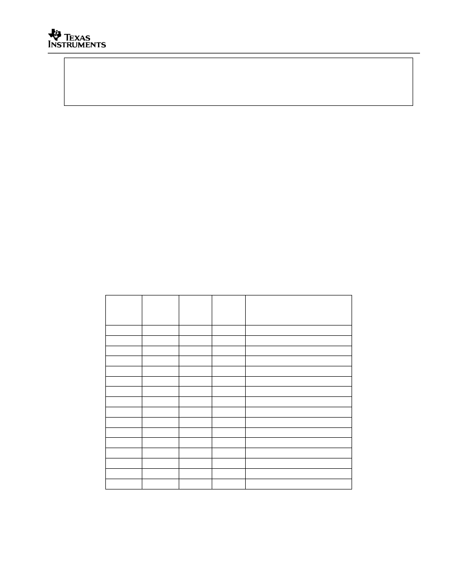
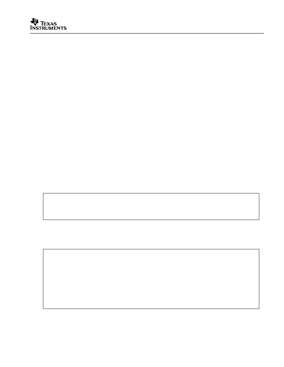
Table 3 shows a listing of the boot mode pin settings for your reference. Refer to the
documentation for your hardware platform for information on configuring the boot mode
pins. For more information on the ‘2833x/’2823x boot modes refer to the device specific
Boot ROM Reference Guide.
Table 3.
2833x/2823x Boot Mode Settings
GPIO87
XA15
PU
GPIO86
XA14
PU
GPIO85
XA13
PU
GPIO84
XA12
PU
Mode
1
1
1
1
Boot to flash 0x33FFF6
1
1
1
0
Call SCI-A boot loader
1
1
0
1
Call SPI-A boot loader
1
1
0
0
Call I2C boot loader
1
0
1
1
Call eCAN-A boot loader
1
0
1
0
Call McBSP-A boot loader
1
0
0
1
Boot to XINTF x16 0x100000
1
0
0
0
Boot to XINTF x32 0x100000
0
1
1
1
Boot to OTP 0x380400
0
1
1
0
Call parallel GPIO boot loader
0
1
0
1
Call parallel XINTF boot loader
0
1
0
0
Boot to M0 SARAM 0x000000
0
0
1
1
Branch to check boot mode
0
0
1
0
Boot to flash, bypass ADC cal
0
0
0
1
Boot to SARAM, bypass ADC cal
0
0
0
0
Boot to SCI-A, bypass ADC cal

V1.30 Quick Start Readme
10
7. Load the code
Once any hardware configuration has been completed, from the Code Composer GEL
pull-down menu select
DSP2833x CpuTimerExample-> Load_Code (for ‘2833x devices)
This will load the .out file into the 28x device, populate the watch window with variables of
interest, reset the part and execute code to the start of the main function. The GEL file is
setup to reload the code every time the device is reset so if this behavior is not desired,
the GEL file can be removed at this time. To remove the GEL file, right click on its name
and select remove.
8. Run the example, add variables to the watch window or examine the memory
contents.
9. Experiment, modify, re-build the example.
If you wish to modify the examples it is suggested that you make a copy of the entire
header file packet to modify or at least create a backup of the original files first. New
examples provided by TI will assume that the base files are as supplied.
Sections 4.2 and 4.3 describe the structure and flow of the examples in more detail.
10. When done, remove the example’s GEL file and project from Code Composer
Studio.
To remove the GEL file, right click on its name and select remove. The examples use the
header files in the DSP2833x_headers directory and shared source in the
DSP2833x_common directory. Only example files specific to a particular example are
located within in the example directory.
Note: Most of the example code included uses the .bit field structures to access
registers. This is done to help the user learn how to use the peripheral and device.
Using the bit fields has the advantage of yielding code that is easier to read and
modify. This method will result in a slight code overhead when compared to using
the .all method. In addition, the example projects have the compiler optimizer
turned off. The user can change the compiler settings to turn on the optimizer if
desired.
4.1.2 Getting Started in Code Composer Studio v4
To get started, follow these steps to load the 32-bit CPU-Timer example. Other examples are
set-up in a similar manner.
1. Have a hardware platform, such as the eZdsp F28335 USB, connected to a host with
Code Composer Studio installed.
NOTE: As supplied, the ‘2833x and ‘2823x example projects are built for the
‘28335/’28235 device. If you are using another 2833x or 2823x device, the memory
definition in the linker command file (.cmd) will need to be changed and the project
rebuilt.

V1.20 Quick Start Readme
11
2. Open the example project.
Each example has its own project directory which is “imported”/opened in Code
Composer Studio v4.
To open the ‘2833x CPU-Timer example project directory, follow the following steps:
e. In Code Composer Studio v 4.x: Project->Import Existing CCS/CCE Eclipse Project.
f. Next to “Select Root Directory”, browse to the CPU Timer example directory:
DSP2833x_examples_ccsv4\cpu_timer (or DSP2823x_examples_ccsv4\cpu_timer).
Select the Finish button.
This will import/open the project in the CCStudio v4 C/C++ Perspective project
window.
3. Edit DSP28_Device.h
In the project window, expand Example_2833xCpuTimer->Includes-> <install directory
base>/DSP2833x_headers/include/ Edit the DSP2833x_Device.h file and make sure
the appropriate device is selected. By default the 28335 is selected. For ‘2823x
devices, the ‘2833x counterpart is selected. For instance, if using F28235,
DSP28_28335 is selected as the TARGET.
/********************************************************************
* DSP2833x_headers\include\DSP2833x_Device.h
********************************************************************/
#define TARGET 1
//---------------------------------------------------------------------------
// User To Select Target Device:
#define DSP28_28335 TARGET
#define DSP28_28334 0
#define DSP28_28332 0
4. Edit DSP2833x_Examples.h
In the project window, expand Example_2833xCpuTimer->Includes-> <install directory
base base>/DSP2833x_common/include/ and edit DSP2833x_Examples.h and specify
the clock rate, the PLL control register value (PLLCR and DIVSEL). These values will
be used by the examples to initialize the PLLCR register and DIVSEL bits.
The default values will result in a 150Mhz SYSCLKOUT frequency.

V1.30 Quick Start Readme
12
/********************************************************************
* DSP2833x_common\include\DSP2833x_Examples.h
********************************************************************/
/*-----------------------------------------------------------------------------
Specify the PLL control register (PLLCR) and divide select (DIVSEL) value.
-----------------------------------------------------------------------------*/
//#define DSP28_DIVSEL 0 // Enable /4 for SYSCLKOUT(default at reset)
//#define DSP28_DIVSEL 1 // Disable /4 for SYSCKOUT
#define DSP28_DIVSEL 2 // Enable /2 for SYSCLKOUT
//#define DSP28_DIVSEL 3 // Enable /1 for SYSCLKOUT
#define DSP28_PLLCR 10
//#define DSP28_PLLCR 9
//#define DSP28_PLLCR 8
//#define DSP28_PLLCR 7
//#define DSP28_PLLCR 6
//#define DSP28_PLLCR 5
//#define DSP28_PLLCR 4
//#define DSP28_PLLCR 3
//#define DSP28_PLLCR 2
//#define DSP28_PLLCR 1
//#define DSP28_PLLCR 0 // (Default at reset) PLL is bypassed in this mode
//----------------------------------------------------------------------------
In DSP2833x_Examples.h, also specify the SYSCLKOUT rate. This value is used to
scale a delay loop used by the examples. The default value is for a 150 Mhz
SYSCLKOUT. If you have a 100 MHz device you will need to adjust these settings
accordingly.
/********************************************************************
* DSP2833x_common\include\DSP2833x_Examples.h
********************************************************************/
……
#define CPU_RATE 6.667L // for a 150MHz CPU clock speed (SYSCLKOUT)
//#define CPU_RATE 7.143L // for a 140MHz CPU clock speed (SYSCLKOUT)
//#define CPU_RATE 8.333L // for a 120MHz CPU clock speed (SYSCLKOUT)
……
In DSP2833x_Examples.h also specify the maximum SYSCLKOUT frequency
(150MHz or 100MHz) by setting it to 1 and the other to 0. This value is used by those
examples with timing dependent code (i.e. baud rates or other timing parameters) to
determine whether 150MHz code or 100MHz code should be run.
The default value is for 150Mhz SYSCLKOUT. If you have a 100MHz device you will
need to adjust these settings accordingly. If you intend to run examples which use
these definitions at a different frequency, then the timing parameters in those examples
must be directly modified accordingly regardless of the setting here.
V1.20 Quick Start Readme
13
/********************************************************************
* DSP2833x_common\include\DSP2833x_Examples.h
********************************************************************/
……
#define CPU_FRQ_100MHZ 0 // 100 MHz CPU Freq - 1 for 100 MHz devices
#define CPU_FRQ_150MHZ 1 // 150 Mhz CPU Freq - default, 1 for 150 MHz devices
//----------------------------------------------------------------------------
5. Review the comments at the top of the main source file:
Example_2833xCpuTimer.c.
A brief description of the example and any assumptions that are made and any external
hardware requirements are listed in the comments at the top of the main source file of
each example. In some cases you may be required to make external connections for the
example to work properly.
6. Perform any hardware setup required by the example.
Perform any hardware setup indicated by the comments in the main source. The CPU-
Timer example only requires that the hardware be setup for “Boot to SARAM” mode.
Other examples may require additional hardware configuration such as connecting pins
together or pulling a pin high or low.
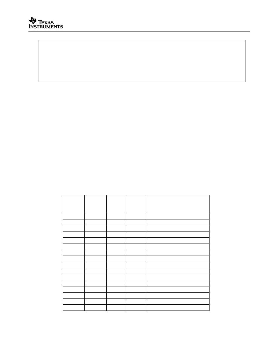
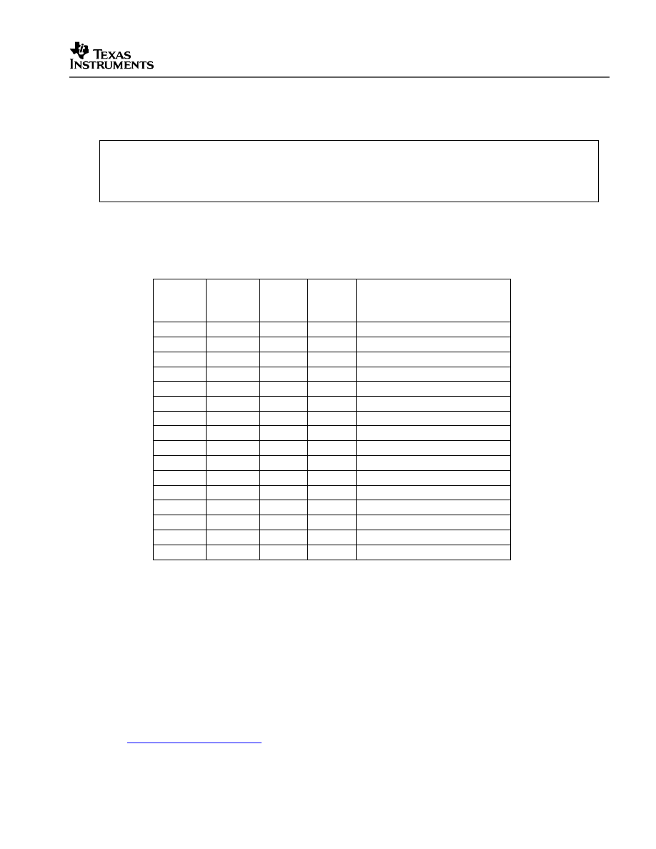
Table 3 shows a listing of the boot mode pin settings for your reference. Refer to the
documentation for your hardware platform for information on configuring the boot mode
pins. For more information on the ‘2833x/’2823x boot modes refer to the device specific
Boot ROM Reference Guide.
Table 4.
2833x/2823x Boot Mode Settings
GPIO87
XA15
PU
GPIO86
XA14
PU
GPIO85
XA13
PU
GPIO84
XA12
PU
Mode
1
1
1
1
Boot to flash 0x33FFF6
1
1
1
0
Call SCI-A boot loader
1
1
0
1
Call SPI-A boot loader
1
1
0
0
Call I2C boot loader
1
0
1
1
Call eCAN-A boot loader
1
0
1
0
Call McBSP-A boot loader
1
0
0
1
Boot to XINTF x16 0x100000
1
0
0
0
Boot to XINTF x32 0x100000
0
1
1
1
Boot to OTP 0x380400
0
1
1
0
Call parallel GPIO boot loader
0
1
0
1
Call parallel XINTF boot loader
0
1
0
0
Boot to M0 SARAM 0x000000
0
0
1
1
Branch to check boot mode
0
0
1
0
Boot to flash, bypass ADC cal
0
0
0
1
Boot to SARAM, bypass ADC cal
0
0
0
0
Boot to SCI-A, bypass ADC cal

V1.30 Quick Start Readme
14
7. Build and Load the code
Once any hardware configuration has been completed, in Code Composer Studio v4, go
to Target->Debug Active Project.
This will open the “Debug Perspective” in CCSv4, build the project, load the .out file into
the 28x device, reset the part, and execute code to the start of the main function. By
default, in Code Composer Studio v4, every time Debug Active Project is selected, the
code is automatically built and the .out file loaded into the 28x device.
8. Run the example, add variables to the watch window or examine the memory
contents.
At the top of the code in the comments section, there should be a list of “Watch
variables”. To add these to the watch window, highlight them and right-click. Then
select Add Watch expression. Now variables of interest are added to the watch
window.
9. Experiment, modify, re-build the example.
If you wish to modify the examples it is suggested that you make a copy of the entire
header file packet to modify or at least create a backup of the original files first. New
examples provided by TI will assume that the base files are as supplied.
Sections 4.2 and 4.3 describe the structure and flow of the examples in more detail.
10. When done, delete the project from the Code Composer Studio v4 workspace.
Go to View->C/C++ Projects to open up your project view. To remove/delete the project
from the workspace, right click on the project’s name and select delete. Make sure the Do
not delete contents button is selected, then select Yes. This does not delete the project
itself. It merely removes the project from the workspace until you wish to open/import it
again.
The examples use the header files in the DSP2833x_headers directory and shared
source in the DSP2833x_common directory. Only example files specific to a particular
example are located within in the example directory.
Note: Most of the example code included uses the .bit field structures to access
registers. This is done to help the user learn how to use the peripheral and device.
Using the bit fields has the advantage of yielding code that is easier to read and
modify. This method will result in a slight code overhead when compared to using
the .all method. In addition, the example projects have the compiler optimizer
turned off. The user can change the compiler settings to turn on the optimizer if
desired.
V1.20 Quick Start Readme
15
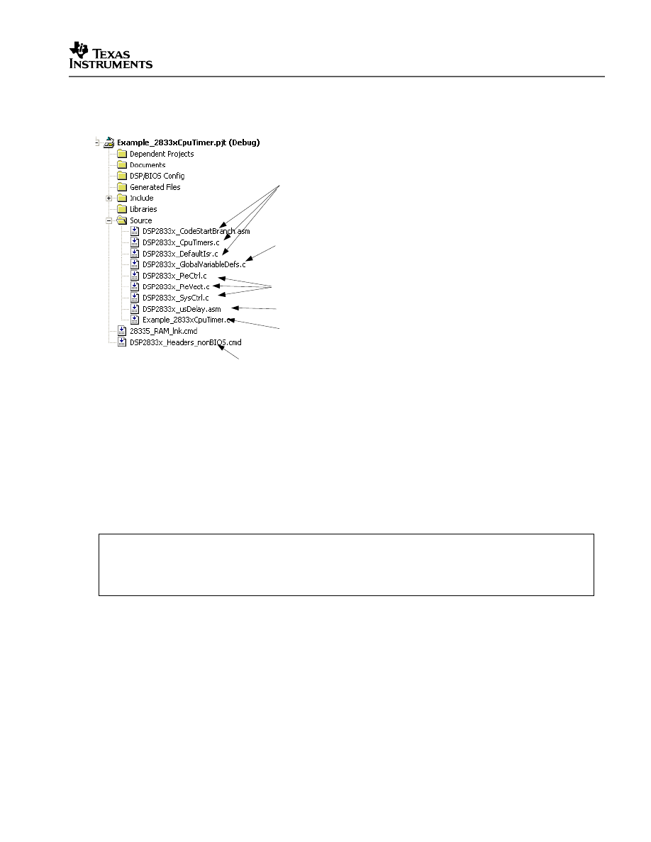
4.2 Example Program Structure
Each of the example programs has a very similar structure. This structure includes unique
source code, shared source code, header files and linker command files.
NOTE:
The ‘2823x example programs use the same source and include files as the ‘2833x example
programs. The only difference between the ‘2823x examples and the ‘2833x examples is that
‘2823x programs are compiled for fixed-point, and ‘2833x programs are compiled for floating-
point.
/********************************************************************
* DSP2833x_examples\cpu_timer\Example_2833xCpuTimer.c
********************************************************************/
#include "DSP28x_Project.h" // Device Headerfile and Examples Include File
•
DSP28x_Project.h
This header file includes DSP2833x_Device.h and DSP2833x_Examples.h. Because the
name is device-generic, example/custom projects can be easily ported between different
device header files. With this file included in the example source files, only the
example/custom project (.pjt) file and DSP28x_Project.h file would need to be modified
when porting source code between different devices. This file is found in the
<base>\DSP2833x_common\include directory.
DSP2833x_GlobalVariableDefs.c
This source file is required to use the header files.
Example Specific Source Code
Common (shared) Source Code
Used by more then one example. These files
contain generic functions for setting up peripherals
to a defined state or functions that may be useful to
re-use in different applications.
Shared Source Code
DSP2833x_Headers_nonBIOS.cmd
Linker file required by the peripheral specific header files.
Memory block specific linker command file

V1.30 Quick Start Readme
16
•
DSP2833x_Device.h
This header file is required to use the header files. This file includes all of the required
peripheral specific header files and includes device specific macros and typedef
statements. This file is found in the <base>\DSP2833x_headers\include directory.
•
DSP2833x_Examples.h
This header file defines parameters that are used by the example code. This file is not
required to use just the DSP2833x peripheral header files but is required by some of the
common source files. This file is found in the <base>\DSP2833x_common\include
directory.
4.2.1 Source Code
Each of the example projects consists of source code that is unique to the example as well as
source code that is common or shared across examples.
•
DSP2833x_GlobalVariableDefs.c
Any project that uses the DSP2833x peripheral header files must include this source file.
In this file are the declarations for the peripheral register structure variables and data
section assignments. This file is found in the <base>\DSP2833x_headers\source
directory.
•
Example specific source code:
Files that are specific to a particular example have the prefix Example_2833x (or
Example_2823x) in their filename. For example Example_2833xCpuTimer.c is specific
to the CPU Timer example and not used for any other example. Example specific files
are located in the <base>\DSP2833x_examples\<example> directory for ‘2833x devices
and in the <base>\DSP2823x_examples\<example> directory for ‘2823x devices.
•
Common source code:
The remaining source files are shared across the examples. These files contain
common functions for peripherals or useful utility functions that may be re-used. Shared
source files are located in the DSP2833x_common\source directory. Users may choose
to incorporate none, some, or the entire shared source into their own new or existing
projects.
4.2.2 Linker Command Files
Each example uses two linker command files. These files specify the memory where the
linker will place code and data sections. One linker file is used for assigning compiler
generated sections to the memory blocks on the device while the other is used to assign the
data sections of the peripheral register structures used by the DSP2833x peripheral header
files.
V1.20 Quick Start Readme
17
•
Memory block linker allocation:
The linker files shown in Table 5 are used to assign sections to memory blocks on the device.
These linker files are located in the <base>\DSP2833x_common\cmd directory. Each
example will use one of the following files depending on the memory used by the example.
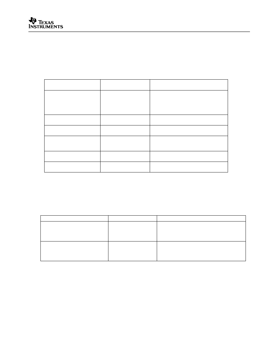
Table 5.
Included Memory Linker Command Files
Memory Linker Command
File Examples
Location
Description
28335_RAM_lnk.cmd
DSP2833x_common\cmd 28335/28235 memory linker command
file. Includes all of the internal SARAM
blocks on a 28335/28235 device. “RAM”
linker files do not include flash or OTP
blocks.
28334_RAM_lnk.cmd
DSP2833x_common\cmd 28335/28235 SARAM memory linker
command file.
28332_RAM_lnk.cmd
DSP2833x_common\cmd 28334/28234 SARAM memory linker
command file.
F28335.cmd
DSP2833x_common\cmd F28335/F28235 memory linker command
file. Includes all Flash, OTP and CSM
password protected memory locations.
F28334.cmd
DSP2833x_common\cmd F28334/F28234 memory linker command
file.
F28332.cmd
DSP2833x_common\cmd F28332/F28232 memory linker command
file.
•
Header file structure data section allocation:
Any project that uses the header file peripheral structures must include a linker command
file that assigns the peripheral register structure data sections to the proper memory
location. These files are described in Table 6.
Table 6.
DSP2833x Peripheral Header Linker Command File
Header File Linker Command File
Location
Description
DSP2833x_Headers_BIOS.cmd
DSP2833x_headers\cmd Linker .cmd file to assign the header file
variables in a BIOS project. This file must be
included in any BIOS project that uses the
header files. Refer to section 5.2.
DSP2833x_Headers_nonBIOS.cmd DSP2833x_headers\cmd Linker .cmd file to assign the header file
variables in a non-BIOS project. This file must
be included in any non-BIOS project that uses
the header files. Refer to section 5.2.
V1.30 Quick Start Readme
18
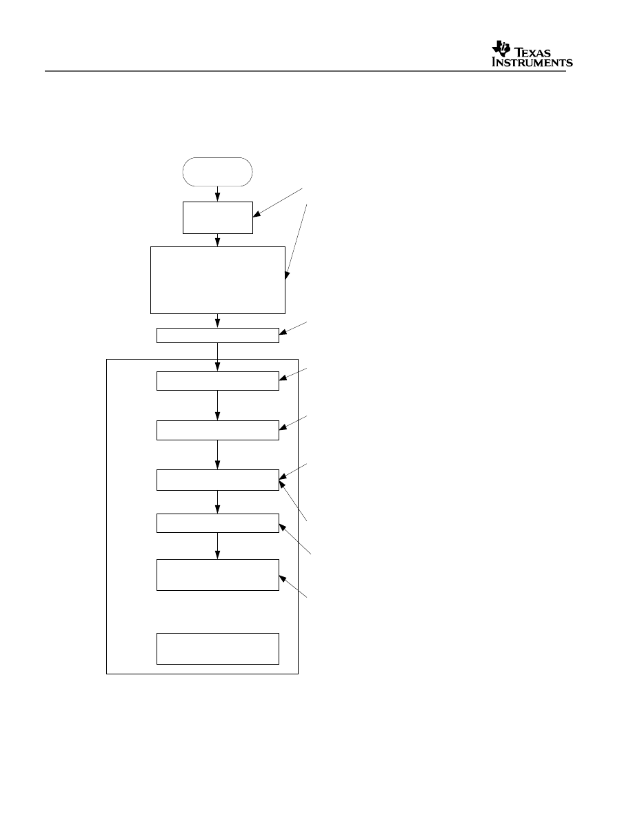
4.3 Example Program Flow
All of the example programs follow a similar recommended flow for setting up a 2833x/2823x
device. Figure 1 outlines this basic flow:
Reset
Boot Sequence
DSP2833x_CodeStartBranch.asm
Disable WD (Optional)
Branch to C Init Routine
C Init
Initialize System Control
Initalize GPIO
Initialize PIE Vector Table
Initalize Peripherals
Example Specific Code
Enable Interrupts
main()
{
}
Boot ROM
DSP2833x_CodeStartBranch.asm
•
Used to re-direct code execution from the boot
entry point to the C Init routine.
•
Code can be configured to disable the
WatchDog if the WD is timing out before main()
is reached.
•
Assigned to the BEGIN section by the linker.
•
Located at 0x000000 for Boot to M0
•
Located at 0x33FFF6 for Boot to Flash
C Init Routine
•
The Compiler's boot.asm which is
automatically included with the runtime
library. This will set OBJMODE to 28x.
Init PLL, Turn on Peripheral Clocks and set the
clock pre-scalers
Disable the WatchDog
Configure GPIO Pins to their peripheral function
or as an input or output as required by the
example.
Initalize the entire PIE Vector Table with pointers
to default Interrupt Service Routines (ISRs) found
in DSP2833x_DefaultIsr.c. It is useful for debug
purposes to have the entire table initalized even if
the ISR is not going to be used.
Remap PIE vectors used by the example to ISR
functions found within the example program.
Initalize the peripherals as required by the
example.
Enable the required PIE and CPU interrupts.
Any additional code required for the example.
Additional Functions and
Interrupt Service Routines
Figure 1. Flow for Example Programs
V1.20 Quick Start Readme
19
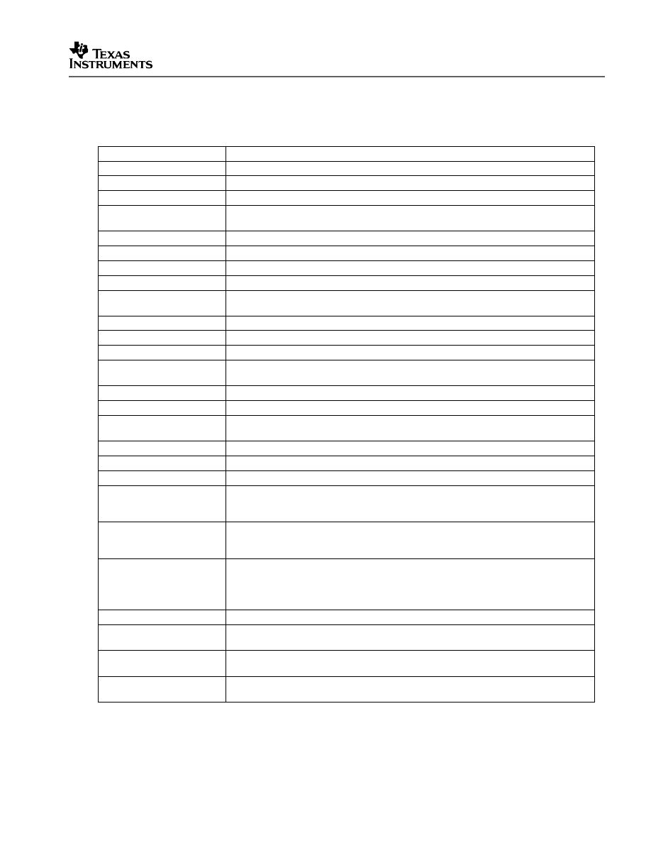
4.4 Included Examples:
Table 7. Included Examples
Example
Description
adc_dma
ADC example with ADC interfaced to DMA. ChannelA0-A3 are converted 10 times.
adc_seq_ovd_tests
ADC test using the sequencer override feature.
adc_seqmode_test
ADC Seq Mode Test. Channel A0 is converted forever and logged in a buffer
adc_soc
ADC example to convert two channels: ADCINA3 and ADCINA2. Interrupts are
enabled and PWM1 is configured to generate a periodic ADC SOC on SEQ1.
cpu_timer
Configures CPU Timer0 and increments a count each time the ISR is serviced.
dma_ram_to_ram
Example of RAM to RAM data block transfer using the DMA.
dma_xintf_to_ram
Example of XINTF to RAM data block transfer using the DMA.
ecan_a_to_b_xmit
Transmit from eCANa to eCANb
ecan_back2back
eCAN self-test mode example. Transmits eCAN data back-to-back at high speed
without stopping.
ecap_apwm
This example sets up the alternate eCAP pins in the APWM mode
ecap_capture_pwm
Captures the edges of a ePWM signal.
epwm_deadband
Example deadband generation via ePWM3
epwm_dma
DMA triggered by SOC from ePWMs. This example also demonstrates ePWM
registers re-mapped to DMA-accessible register space.
epwm_timer_interrupts
Starts ePWM1-ePWM6 timers. Every period an interrupt is taken for each ePWM.
epwm_trip_zone
Uses the trip zone signals to set the ePWM signals to a particular state.
epwm_up_aq
Generate a PWM waveform using an up count time base ePWM1-ePWM3 are
used.
epwm_updown_aq
Generate a PWM waveform using an up/down time base. ePWM- ePWM3 are used.
eqep_freqcal
Frequency cal using eQEP1
eqep_pos_speed
Pos/speed calculation using eQEP1
external_interrupt
Configures GPIO0 as XINT1 and GPIO1 as XINT2. The interrupts are fired by
toggling GPIO30 and GPIO31 which are connected to XINT1 (GPIO0) and XINT2
(GPIO1) externally by the user.
flash
ePWM timer interrupt project moved from SARAM to Flash. Includes steps that
were used to convert the project from SARAM to Flash. Some interrupt service
routines are copied from FLASH to SARAM for faster execution.
fpu
Two projects illustrating the difference between code compiled with floating-point
hardware (FPU) and fixed-point hardware (using software to simulate floating-point).
Note: This example is not included in the DSP2823x_examples directory because
DSP2823x devices do not have an FPU.
gpio_setup
Three examples of different pinout configurations.
gpio_toggle
Toggles all of the I/O pins using different methods – DATA, SET/CLEAR and
TOGGLE registers. The pins can be observed using an oscilloscope.
hrpwm
Sets up ePWM1-ePWM4 and controls the edge of output A using the HRPWM
extension. Both rising edge and falling edge are controlled.
hrpwm_sfo
Use TI's MEP Scale Factor Optimizer (SFO) library to change the HRPWM. This
version of the SFO library supports HRPWM on ePWM channels 1-4 only.
V1.30 Quick Start Readme
20
Included Examples Continued…
hrpwm_sfo_v5
Use TI’s MEP Scale Factor Optimizer (SFO) library version 5 to change the
HRPWM. This version of the SFO library supports HRPWM on up to 16 ePWM
channels (if available)
hrpwm_slider
This is the same as the hrpwm example except the control of CMPAHR is now
controlled by the user via a slider bar. The included .gel file sets up the slider.
i2c_eeprom
Communicate with the EEPROM on the eZdsp F28335 USB platform via I2C
lpm_haltwake
Puts device into low power halt mode. GPIO0 is configured to wake the device from
halt when an external high-low-high pulse is applied to it.
lpm_idlewake
Puts device into low power idle mode. GPIO0 is configured as XINT1 pin. When an
XINT1 interrupt occurs due to a falling edge on GPIO0, the device is woken from
idle.
lpm_standbywake
Puts device into low power standby mode. GPIO0 is configured to wake the device
from halt when an external high-low-high pulse is applied to it.
mcbsp_loopback
McBSP-A example that uses the peripheral’s loop-back testmode to send data.
mcbsp_loopback_dma
McBSP-A example that uses the peripheral’s loop-back testmode with the DMA to
send and receive data.
mcbsp_loopback_interrupts McBSP-A example that uses the peripheral’s loop-back testmode to send data.
Interrupts are used in this example.
mcbsp_spi_loopback
McBSP-A example that configures the peripheral for SPI mode and uses the loop-
back testmode to send data.
sci_autobaud
Externally connect SCI-A to SCI-B and send data between the two peripherals.
Baud lock is performed using the autobaud feature of the SCI. This test is repeated
for different baud rates.
sci_echoback
SCI-A example that can be used to echoback to a terminal program such as
hyperterminal. A transceiver and a connection to a PC is required.
scia_loopback
SCI-A example that uses the peripheral’s loop-back test mode to send data.
scia_loopback_interrupts
SCI-A example that uses the peripheral’s loop-back test mode to send data. Both
interrupts and FIFOs are used in this example.
spi_loopback
SPI-A example that uses the peripherals loop-back test mode to send data.
spi_loopback_interrupts
SPI-A example that uses the peripherals loop-back test mode to send data. Both
interrupts and FIFOs are used in this example.
sw_prioritized_interrupts
The standard hardware prioritization of interrupts can be used for most applications.
This example shows a method for software to re-prioritize interrupts if required.
timed_led_blink
This example blinks GPIO32 (LED on the eZdsp) at a rate of 1 Hz using CPU Timer
0.
watchdog
Illustrates feeding the dog and re-directing the watchdog to an interrupt.
xintf_run_from
This example shows how to run from XINTF zone 7 and configure the XINTF
memory interface on the F28335 eZdsp.
V1.20 Quick Start Readme
21
4.5 Executing the Examples From Flash
Most of the DSP2833x/2823x examples execute from SARAM in “boot to SARAM” mode.
One example, DSP2833x_examples\Flash (or DSP2823x_examples\Flash), executes from
flash memory in “boot to flash” mode. This example is the PWM timer interrupt example with
the following changes made to execute out of flash:
1. Change the linker command file to link the code to flash.
Remove 28335_RAM_lnk.cmd from the project and add one of the flash based linker files
(ex: F28335.cmd, F28334.cmd, or F28332.cmd). These files are located in the
<base>DSP2833x_common\cmd\ directory.
2. Add the DSP2833x_common\source\DSP2833x_CSMPasswords.asm to the project.
This file contains the passwords that will be programmed into the Code Security Module
(CSM) password locations. Leaving the passwords set to 0xFFFF during development is
recommended as the device can easily be unlocked. For more information on the CSM
refer to the appropriate System Control and Interrupts Reference Guide.
3. Modify the source code to copy all functions that must be executed out of SARAM
from their load address in flash to their run address in SARAM.
In particular, the flash wait state initialization routine must be executed out of SARAM.
In the DSP2833x/2823x examples, functions that are to be executed from SARAM
have been assigned to the ramfuncs section by compiler CODE_SECTION #pragma
statements as shown in the example below.
/********************************************************************
* DSP2833x_common\source\DSP2833x_SysCtrl.c
********************************************************************/
#pragma CODE_SECTION(InitFlash, "ramfuncs");
The ramfuncs section is then assigned to a load address in flash and a run address in
SARAM by the memory linker command file as shown below:
/********************************************************************
* DSP2833x_common\include\F28335.cmd
********************************************************************/
SECTIONS
{
ramfuncs : LOAD = FLASHD,
RUN = RAML0,
LOAD_START(_RamfuncsLoadStart),
LOAD_END(_RamfuncsLoadEnd),
RUN_START(_RamfuncsRunStart),
PAGE = 0
}

V1.30 Quick Start Readme
22
The linker will assign symbols as specified above to specific addresses as follows:
Address
Symbol
Load start address
RamfuncsLoadStart
Load end address
RamfuncsLoadEnd
Run start address
RamfuncsRunStart
These symbols can then be used to copy the functions from the Flash to SARAM using
the included example MemCopy routine or the C library standard memcopy() function.
To perform this copy from flash to SARAM using the included example MemCopy
function:
a. Add the file DSP2833x_common\source\DSP2833x_MemCopy.c to the project.
b. Add the following function prototype to the example source code. This is done for
you in the DSP2833x_Examples.h file.
/********************************************************************
* DSP2833x_common\include\DSP2833x_Examples.h
********************************************************************/
MemCopy(&RamfuncsLoadStart, &RamfuncsLoadEnd, &RamfuncsRunStart);
c. Add the following variable declaration to your source code to tell the compiler that
these variables exist. The linker command file will assign the address of each of
these variables as specified in the linker command file as shown in step 3. For the
DSP2833x/2823x example code this has is already done in DSP2833x_Examples.h.
/********************************************************************
* DSP2833x_common\include\DSP2833x_GlobalPrototypes.h
********************************************************************/
extern Uint16 RamfuncsLoadStart;
extern Uint16 RamfuncsLoadEnd;
extern Uint16 RamfuncsRunStart;
d. Modify the code to call the example MemCopy function for each section that needs to
be copied from flash to SARAM.
/********************************************************************
* DSP2833x_examples\Flash source file
********************************************************************/
MemCopy(&RamfuncsLoadStart, &RamfuncsLoadEnd, &RamfuncsRunStart);
V1.20 Quick Start Readme
23
4. Modify the code to call the flash initialization routine:
This function will initialize the wait states for the flash and enable the Flash Pipeline mode.
/********************************************************************
* DSP2833x peripheral example .c file
********************************************************************/
InitFlash();
5. Set the required jumpers for “boot to Flash” mode.
The required jumper settings for each boot mode are shown in Table 8.
Table 8.
2833x/2823x Boot Mode Settings
GPIO87
XA15
PU
GPIO86
XA14
PU
GPIO85
XA13
PU
GPIO84
XA12
PU
Mode
1
1
1
1
Boot to flash 0x33FFF6
1
1
1
0
Call SCI-A boot loader
1
1
0
1
Call SPI-A boot loader
1
1
0
0
Call I2C boot loader
1
0
1
1
Call eCAN-A boot loader
1
0
1
0
Call McBSP-A boot loader
1
0
0
1
Boot to XINTF x16 0x100000
1
0
0
0
Boot to XINTF x32 0x100000
0
1
1
1
Boot to OTP 0x380400
0
1
1
0
Call parallel GPIO boot loader
0
1
0
1
Call parallel XINTF boot loader
0
1
0
0
Boot to M0 SARAM 0x000000
0
0
1
1
Branch to check boot mode
0
0
1
0
Boot to flash, bypass ADC cal
0
0
0
1
Boot to SARAM, bypass ADC cal
0
0
0
0
Boot to SCI-A, bypass ADC cal
Refer to the documentation for your hardware platform for information on configuring the
boot mode selection pins.
For more information on the ‘2833x/’2823x boot modes refer to the appropriate Boot
ROM Reference Guide.
6. Program the device with the built code.
In Code Composer Studio v4.0, when code is loaded into the device during debug, it
automatically programs to flash memory.
This can also be done using SDFlash available from Spectrum Digital’s website
(
www.spectrumdigital.com
). In addition the C2000 On-chip Flash programmer plug-in
V1.30 Quick Start Readme
24
for Code Composer Studio v3.0 can be used. These tools will be updated to support
new devices as they become available. Please check for updates.
7. In Code Composer Studio v3, to debug, load the project in CCS, select File->Load
Symbols->Load Symbols Only.
It is useful to load only symbol information when working in a debugging environment
where the debugger cannot or need not load the object code, such as when the code is in
ROM or flash. This operation loads the symbol information from the specified file.
In Code Composer Studio 4, the .out file can be loaded as-is, and the flash will
automatically be programmed correctly.
4.6 Converting Floating-Point Compiled Examples to Fixed-Point and Vice Versa
This section applies to ‘2833x devices only.
Because the ‘2833x is a floating-point device, all of the DSP2833x examples (unless
otherwise denoted in the example description) are configured for floating-point. In some
cases, it may be desirable to compile the code for fixed-point instead of floating-point. For
instance, because Code Composer Studio V3.1 and prior versions of CCS only support fixed-
point compiled projects, if the example project needs to be compiled and run on one of these
CCS versions, it must be converted to fixed-point first.
To convert the examples so they compile for fixed-point, certain steps must be taken. The
following steps are demonstrated on the example in DSP2833x_examples\fpu. The directory
includes two projects with identical C-code— one compiled using fixed-point instructions and
the other compiled using floating-point instructions.
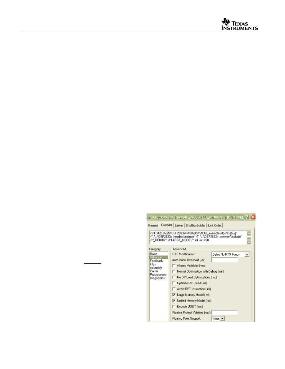
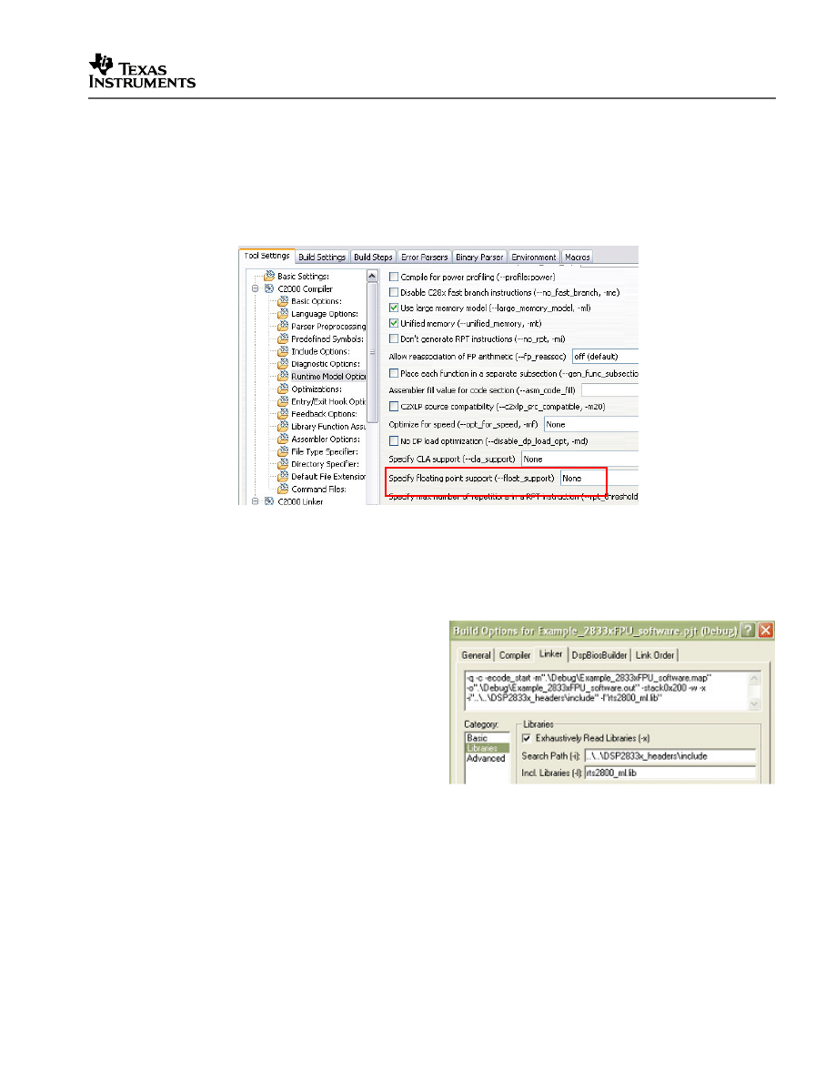
1. Configure the compiler build options for fixed-point instead of floating-point.
In Code Composer Studio v3.x:
a. Go to Project->Build Options..
b. In CCStudio v3.x: in the Compiler
tab window, click on the “Advanced”
category and select “None” from the
“Floating point support: ” pull-down
menu OR remove:
--float_support=fpu32
from the
textbox at the top of the window.
V1.20 Quick Start Readme
25
In Code Composer Studio v4.x:
a. Go to Project-> Properties
b. Select C/C++ Build. Then in the Tool Settings tab, select “C2000 Compiler”-
>Runtime Model Options. In the screen that appears on the right, select “None”
from the “Specify floating point support (--float_support)” pull-down menu. Then
select the Apply button at the bottom of the window.
2. Use the fixed-point version of the rts2800.lib library instead of the floating-point
version.
In Code Composer Studio v3.x
a. Click on the “Linker” tab at the top of
the window.
b. Click on the “Libraries” category and
in the “Incl. Libraries” textbox,
replace the floating-point version of
the rts2800 library
(
rts2800_fpu32.lib
) with the fixed-
point large memory version
:
rts2800_ml.lib.
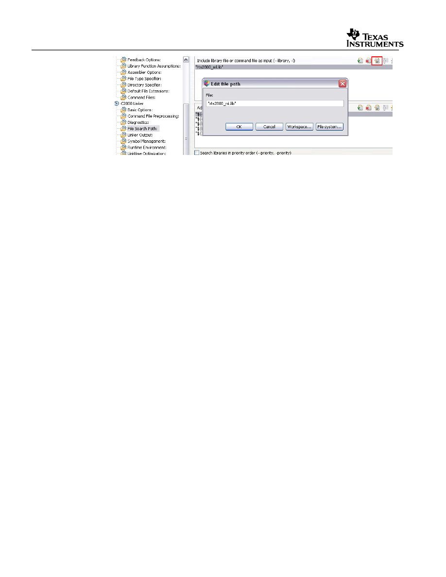
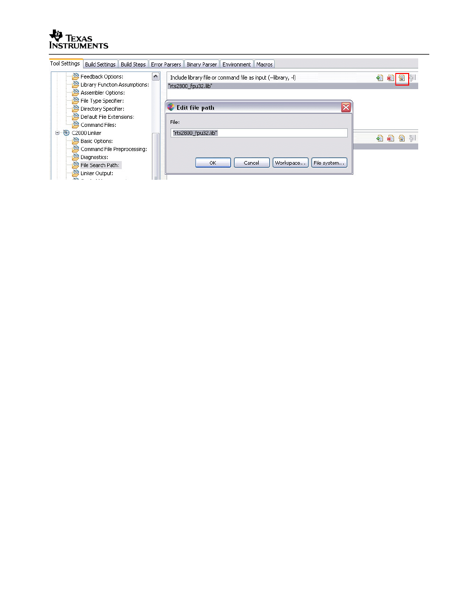
In Code Composer Studio v4.x
a. In the Tool Settings tab, go to “C2000 Linker->File Search Path:”
b. In the upper box on the right labeled “Include library file or command file as input (-
-library, -l)”, select the “Edit” icon in the top right, and change “rts2800_fpu32.lib”
(for floating-point version of the rts2800 library) to “rts2800_ml.lib” (for fixed-point
large memory model version of the library).
V1.30 Quick Start Readme
26
3. Replace any floating-point compiled libraries included in the project with their fixed-
point equivalents.
If your project is compiled for floating-point (fpu32 option), then any libraries included
by your project must also be compiled for floating-point. Likewise, if your project is
compiled for fixed-point, the included libraries must also be compiled for fixed-point.
In Code Composer Studio v3.x:
a. In the Project View window, click on the plus sign next to the “Libraries” folder to
view the libraries.
b. Right click on the floating-point compiled library and select “Remove from Project”.
c. Then right-click on the “Libraries” folder and select “Add Files to Project…”
d. In the DSP2833x_common\lib directory or in the directory where the fixed-point
compiled version of your library is located, select the fixed-point version of the
library to add it to your project.
In Code Composer Studio v4.x:
a. In the Project window, right click on “SFO_TI_Build_V5_fpu.lib”, and select
“Delete”.
b. Then, right-click on the project name and select “New->File”.
c. Select your project. Then at the bottom of the window, click the “Advanced>>”
button.
d. Check the “Link to file in the file system” checkbox.
e. Now you have 2 options for adding the floating-point version of the library to your
project. Option A is the quickest way, but only works on your own computer as
long as the library remains at the same location on your computer (the project will
break on another computer or if you move the library to a different location on your
computer). Option B takes a few more steps, but it can be used if you plan to move
the project and associated files to another location on the same or different
computer.
V1.20 Quick Start Readme
27
i. Option A: Select “Browse…” and navigate to where the floating-point version
of your library is located, and select the library to replace the fixed-point
version. (for instance, “SFO_TI_Build_V5_fpu.lib” is replaced with
“SFO_TI_Build_V5.lib”).
ii. Option B: Select “Variables…”, and select the macro pointing to the path of
your header file installation direction. (i.e. select
INSTALLROOT_2833X_V130 which points to the default installation
directory path for V1.30 of the 2833x header files and peripheral
examples). Then select “Extend…”, and navigate to where the fixed-point
version of your library is located, and select the library to replace the
floating-point version. (for instance, “SFO_TI_Build_V5_fpu.lib” is replaced
with “SFO_TI_Build_V5.lib”).
After these 3 steps are performed, the floating-point example project has been converted to
fixed-point and can be re-compiled and built for fixed-point. To convert a fixed-point example
back into floating-point, the following steps must be taken:
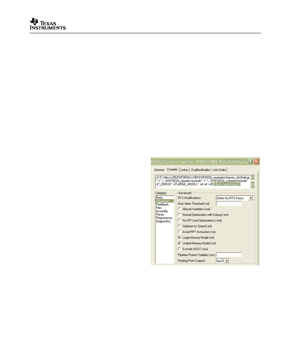
1. Configure the compiler build options for
floating-point instead of fixed-point.
In Code Composer Studio 3.x:
a. Go to Project->Build Options.
b.
In the Compiler tab window, click on
the “Advanced” category and select
“fpu32” from the “Floating point
support: ” pull-down menu OR add:
-v28 --float_support=fpu32
to the textbox at the top of the
window (The –v28 option may
already be in the textbox).
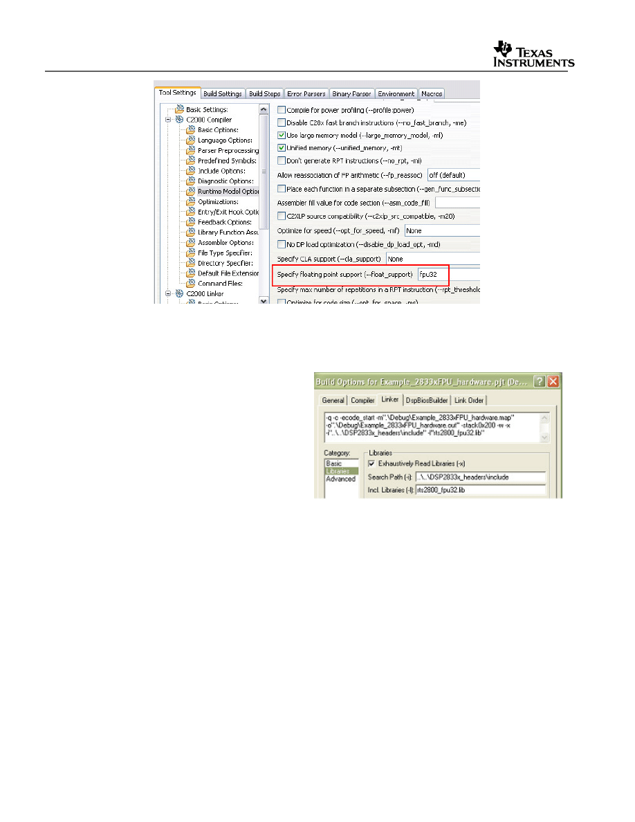
In Code Composer Studio v4:
a. Go to Project-> Properties.
b. In CCStudio v4.0: Select C/C++ Build. Then in the Tool Settings tab, select “C2000
Compiler”->Runtime Model Options. In the screen that appears on the right, select
“fpu32” from the “Specify floating point support (--float_support)” pull-down menu.
Then select the Apply button at the bottom of the window.
V1.30 Quick Start Readme
28
2. Use the floating-point version of the rts2800.lib library instead of the fixed-point
version.
In Code Composer Studio v3.x:
a. Click on the “Linker” tab at the
top of the window.
b. Click on the “Libraries” category
and in the “Incl. Libraries”
textbox, replace the fixed-point
version of the rts2800 library
(
rts2800_ml.lib or
rts2800.lib
) with the floating-
point version
:
rts2800_fpu32.lib .
In Code Composer Studio v4.x:
a. In the Tool Settings tab, go to “C2000 Linker->File Search Path:”
b. In the upper box on the right labeled “Include library file or command file as input (-
-library, -l)”, select the “Edit” icon in the top right, and change “rts2800_ml.lib” (for
fixed-point large memory version of the rts2800 library) to “rts2800_fpu32.lib” (for
the floating-point version of the library).
V1.20 Quick Start Readme
29
3. Replace any fixed-point compiled libraries included in the project with their floating-
point equivalents.
In Code Composer Studio v3.x:
a. In the Project View window, click on the plus sign next to the “Libraries” folder to
view the libraries.
b. Right click on the floating-point compiled version of the library and select “Remove
from Project”.
c. Then right-click on the “Libraries” folder and select “Add Files to Project…”
d. In the DSP2833x_common\lib directory or in the directory where the floating-point
compiled version of your library is located, select the fixed-point version of the
library to add it to your project.
In Code Composer Studio v4.x:
a. In the Project window, right click on “SFO_TI_Build_V5.lib”, and select “Delete”.
b. Then, right-click on the project name and select “New->File”.
c. Select your project. Then at the bottom of the window, click the “Advanced>>”
button.
d. Check the “Link to file in the file system” checkbox.
e. Now you have 2 options for adding the floating-point version of the library to your
project. Option A is the quickest way, but only works on your own computer as
long as the library remains at the same location on your computer (the project will
break on another computer or if you move the library to a different location on your
computer). Option B takes a few more steps, but it can be used if you plan to move
the project and associated files to another location on the same or different
computer.
iii. Option A: Select “Browse…” and navigate to where the floating-point version
of your library is located, and select the library to replace the fixed-point
version. (for instance, “SFO_TI_Build_V5.lib” is replaced with
“SFO_TI_Build_V5_fpu.lib”).

V1.30 Quick Start Readme
30
iv. Option B: Select “Variables…”, and select the macro pointing to the path of
your header file installation direction. (i.e. select
INSTALLROOT_2833X_V130 which points to the default installation
directory path for V1.30 of the 2833x header files and peripheral
examples). Then select “Extend…”, and navigate to where the floating-
point version of your library is located, and select the library to replace the
fixed-point version. (for instance, “SFO_TI_Build_V5.lib” is replaced with
“SFO_TI_Build_V5_fpu.lib”).
After these 3 steps are performed, the fixed-point example project has been converted to
floating-point and can be re-compiled and built for floating-point.
V1.20 Quick Start Readme
31
5 Steps for Incorporating the Header Files and Sample Code
Follow these steps to incorporate the peripheral header files and sample code into your own
projects. If you already have a project that uses the DSP280x or DSP281x header files then
also refer to Section 7 for migration tips.
5.1 Before you begin
Before you include the header files and any sample code into your own project, it is
recommended that you perform the following:
1. Load and step through an example project.
Load and step through an example project to get familiar with the header files and
sample code. This is described in Section 4.
2. Create a copy of the source files you want to use.
DSP2833x_headers: code required to incorporate the header files into your project
DSP2833x_common: shared source code much of which is used in the example
projects.
DSP2823x_examples: ‘2823x fixed-point compiled example projects that use the header
files and shared code.
DSP2833x_examples: ‘2833x floating-point compiled example projects that use the
header files and shared code.
5.2 Including the DSP2833x Peripheral Header Files
Including the DSP2833x header files in your project will allow you to use the bit-field structure
approach in your code to access the peripherals on the DSP. To incorporate the header files
in a new or existing project, perform the following steps:
1. #include “DSP2833x_Device.h” (or #include “DSP28x_Project.h” ) in your source
files.
The DSP2833x_Device.h include file will in-turn include all of the peripheral specific
header files and required definitions to use the bit-field structure approach to access the
peripherals.
/********************************************************************
* User’s source file
********************************************************************/
#include “DSP2833x_Device.h”
Another option is to #include “DSP28x_Project.h” in your source files, which in-turn
includes “DSP2833x_Device.h” and “DSP2833x_Examples.h” (if it is not necessary to
include common source files in the user project, the #include “DSP2833x_Examples.h”
line can be deleted). Due to the device-generic nature of the file name, user code is
easily ported between different device header files. With this file included in the user’s
V1.30 Quick Start Readme
32
source files, only the project (.pjt) file and DSP28x_Project.h file would need to be
modified when porting source code between different devices.
/********************************************************************
* User’s source file
********************************************************************/
#include “DSP28x_Project.h”
Edit DSP2833x_Device.h and select the target you are building for:
In the below example, the file is configured to build for the ‘28335/’28235 device.
/********************************************************************
* DSP2833x_headers\include\DSP2833x_Device.h
********************************************************************/
#define TARGET 1
#define DSP28_28335 TARGET // Selects '28335/'28235
#define DSP28_28334 0 // Selects '28334/'28234
#define DSP28_28332 0 // Selects '28332/'28232… etc
By default, the ‘28335/’28235 device is selected.
2. Add the source file DSP2833x_GlobalVariableDefs.c to the project.
This file is found in the DSP2833x_headers\source\ directory and includes:
– Declarations for the variables that are used to access the peripheral registers.
– Data section #pragma assignments that are used by the linker to place the variables
in the proper locations in memory.
3. Add the appropriate DSP2833x header linker command file to the project.
As described in Section 3, when using the DSP2833x header file approach, the data
sections of the peripheral register structures are assigned to the memory locations of
the peripheral registers by the linker.
To perform this memory allocation in your project, one of the following linker command
files located in DSP2833x_headers\cmd\ must be included in your project:
– For non-DSP/BIOS
†
projects:
DSP2833x_Headers_nonBIOS.cmd
– For DSP/BIOS projects:
DSP2833x_Headers_BIOS.cmd
†
DSP/BIOS is a trademark of Texas Instruments
V1.20 Quick Start Readme
33
The method for adding the header linker file to the project depends on the version of
Code Composer Studio being used.
Code Composer Studio V2.2 and later:
As of CCS 2.2, more then one linker
command file can be included in a project.
Add the appropriate header linker command
file (BIOS or nonBIOS) directly to the project.
Code Composer Studio prior to V2.2
Prior to CCS 2.2, each project contained only
one main linker command file. This file can, however, call additional .cmd files as
needed. To include the required memory allocations for the DSP2833x header files,
perform the following two steps:
1) Update the project’s main linker command (.cmd) file to call one of the supplied
DSP2833x peripheral structure linker command files using the -l option.
/********************************************************************
* User’s linker .cmd file
********************************************************************/
/* Use this include file only for non-BIOS applications */
-l DSP2833x_Headers_nonBIOS.cmd
/* Use this include file only for BIOS applications */
/* -l DSP2833x_Headers_BIOS.cmd */
2) Add the directory path to the DSP2833x peripheral linker .cmd file to your
project.
Code Composer Studio 3.x:
a. Open the menu: Project->Build Options
b. Select the Linker tab and then Select Basic.
c. In the Library Search Path, add the directory path to the location of the
DSP2833x_headers\cmd directory on your system.
Code Composer Studio 4.x:
Method #1:
a. Right-click on the project in the project window of the C/C++ Projects perspective.
b. Select Link Files to Project…
c. Navigate to the DSP2833x_headers\cmd directory on your system and select the
desired .cmd file.
V1.30 Quick Start Readme
34
Note: The limitation with Method #1 is that the path to <install
directory>\DSP2833x_headers\cmd\<cmd file>.cmd is fixed on your PC. If you
move the installation directory to another location on your PC, the project will
“break” because it still expects the .cmd file to be in the original location. Use
Method #2 if you are using “linked variables” in your project to ensure your
project/installation directory is portable across computers and different locations
on the same PC. (For more information, see:
http://tiexpressdsp.com/index.php/Portable_Projects_in_CCSv4_for_C2000
)
Method #2:
a. Right-click on the project in the project window of the C/C++ Projects perspective.
b. Select New->File.
c. Click on the Advanced>> button to expand the window.
d. Check the Link to file in the file system checkbox.
e. Select the Variables… button. From the list, pick the linked variable (macro defined in
your macros.ini file) associated with your installation directory. (For the 2833x header
files, this is INSTALLROOT_2833X_V<version #>). For more information on linked
variables and the macros.ini file, see:
http://tiexpressdsp.com/index.php/Portable_Projects_in_CCSv4_for_C2000#Method_
.232_for_Linking_Files_to_Project
:
f. Click on the Extend…” button. Navigate to the desired .cmd file and select OK.
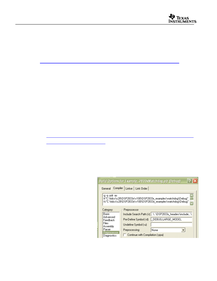
4. Add the directory path to the DSP2833x header files to your project.
Code Composer Studio 3.x:
To specify the directory where
the header files are located:
a. Open the menu:
Project->Build Options
b. Select the Compiler tab
c. Select pre-processor.
d. In the Include Search Path,
add the directory path to
the location of
DSP2833x_headers\includ
e on your system.
Code Composer Studio 4.x:
To specify the directory where the header files are located:
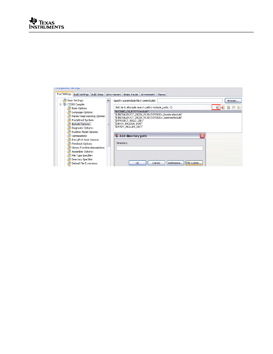
V1.20 Quick Start Readme
35
a. Open the menu: Project->Properties.
b. In the menu on the left, select “C/C++ Build”.
c. In the “Tool Settings” tab, Select “C2000 Compiler -> Include Options:”
d. In the “Add dir to #include search path (--include_path, -I” window, select the “Add”
icon in the top right corner.
e. Select the “File system…” button and navigate to the directory path of
DSP2833x_headers\include on your system.
5. Additional suggested build options:
The following are additional compiler and linker options. The options can all be set via
the Project->Build Options menu in CCStudio v3.x and the Project->Properties menu
under C/C++ Build in CCStudio v4.x.
– Compiler Tab:
-ml
Select Advanced and check –ml
Build for large memory model. This setting allows data sections to reside
anywhere within the 4M-memory reach of the 28x devices.
-pdr
Select Diagnostics and check –pdr
Issue non-serious warnings. The compiler uses a warning to indicate code that is
valid but questionable. In many cases, these warnings issued by enabling -pdr
can alert you to code that may cause problems later on.
– Linker Tab:
-w
Select Advanced and check –w
Warn about output sections. This option will alert you if any unassigned memory
sections exist in your code. By default the linker will attempt to place any
unassigned code or data section to an available memory location without alerting
the user. This can cause problems, however, when the section is placed in an
unexpected location.
-e
Select Basic and enter Code Entry Point –e

V1.30 Quick Start Readme
36
Defines a global symbol that specifies the primary entry point for the output
module. For the DSP2833x/DSP2823x examples, this is the symbol “code_start”.
This symbol is defined in the
DSP2833x_common\source\DSP2833x_CodeStartBranch.asm file. When you
load the code in Code Composer Studio, the debugger will set the PC to the
address of this symbol. If you do not define a entry point using the –e option,
then the linker will use _c_int00 by default.
5.3 Including Common Example Code
Including the common source code in your project will allow you to leverage code that is
already written for the device. To incorporate the shared source code into a new or existing
project, perform the following steps:
1. #include “DSP2833x_Examples.h” (or “DSP28x_Project.h”) in your source files.
The “DSP2833x_Examples.h” include file will include common definitions and
declarations used by the example code.
/********************************************************************
* User’s source file
********************************************************************/
#include “DSP2833x_Examples.h”
Another option is to #include “DSP28x_Project.h” in your source files, which in-turn
includes “DSP2833x_Device.h” and “DSP2833x_Examples.h”. Due to the device-
generic nature of the file name, user code is easily ported between different device
header files. With this file included in the user’s source files, only the project (.pjt) file
and DSP28x_Project.h file would need to be modified when porting source code
between different devices.
/********************************************************************
* User’s source file
********************************************************************/
#include “DSP28x_Project.h”
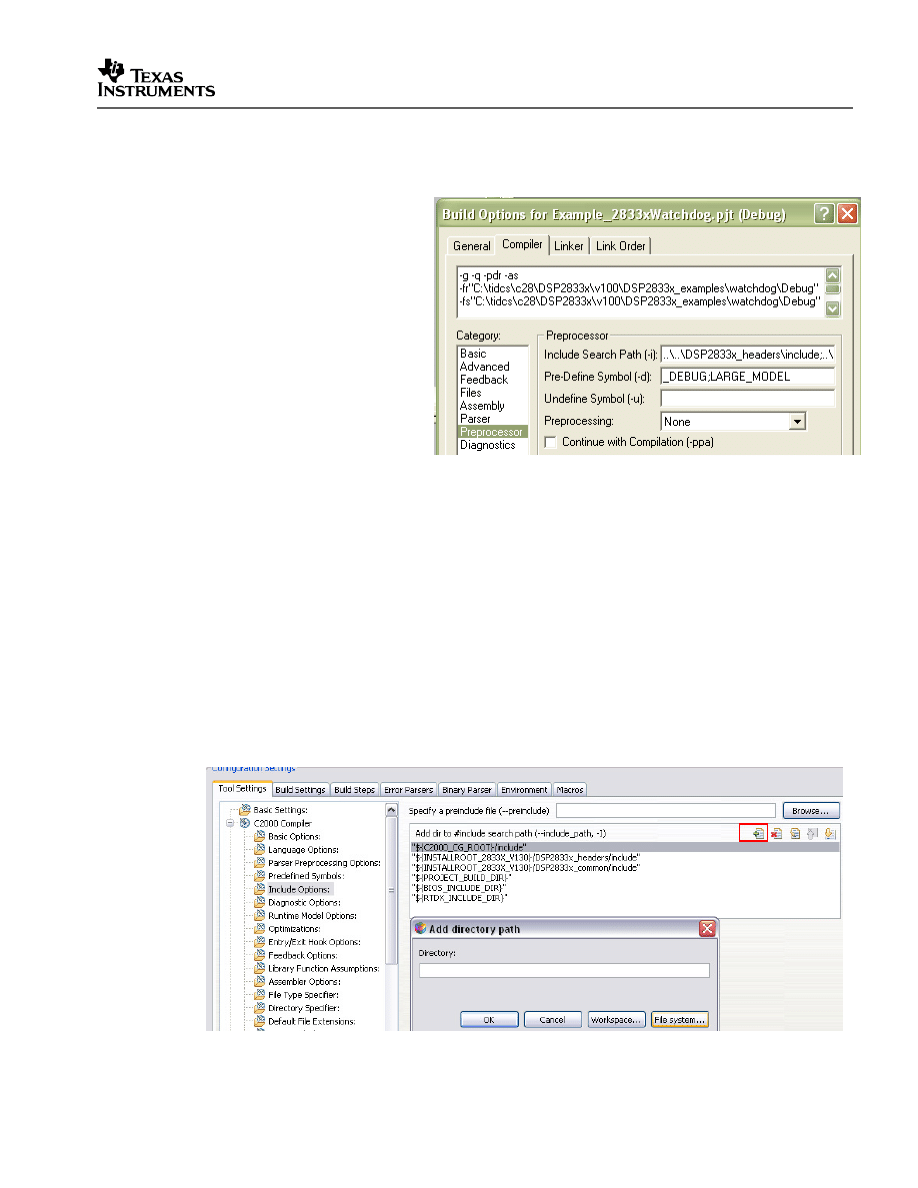
V1.20 Quick Start Readme
37
2. Add the directory path to the example include files to your project.
Code Composer Studio 3.x
To specify the directory where
the header files are located:
a. Open the menu:
Project->Build Options
b. Select the Compiler tab
c. Select pre-processor.
d. In the Include Search Path,
add the directory path to the
location of
DSP2833x_common/include
on your system.
Use a semicolon between
directories.
For example the directory path for the included projects is:
..\..\DSP2833x_headers\include;..\..\DSP2833x_common\include
Code Composer Studio 4.x:
To specify the directory where the header files are located:
a. Open the menu: Project->Properties.
b. In the menu on the left, select “C/C++ Build”.
c. In the “Tool Settings” tab, Select “C2000 Compiler -> Include Options:”
d. In the “Add dir to #include search path (--include_path, -I” window, select the “Add”
icon in the top right corner.
e. Select the “File system…” button and navigate to the directory path of
DSP2833x_headers\include on your system.
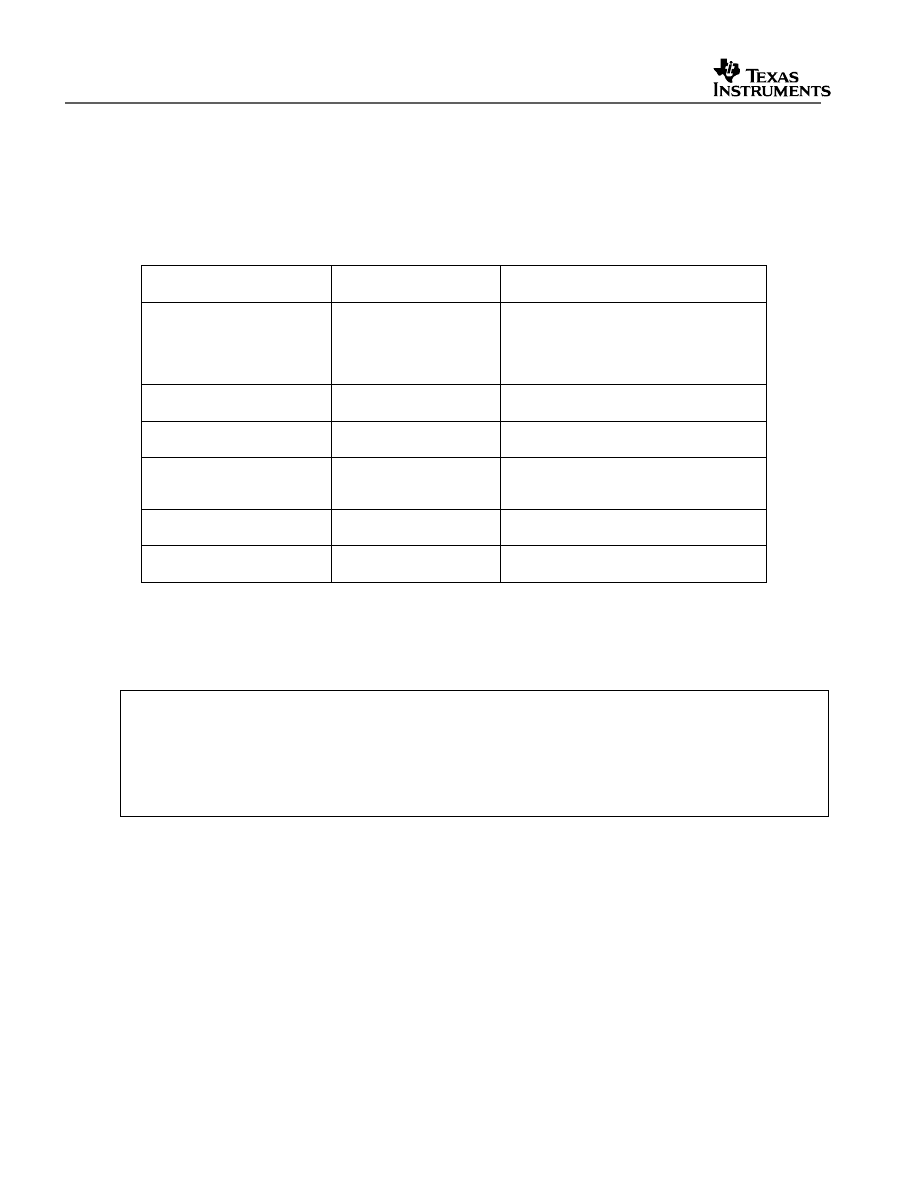
V1.30 Quick Start Readme
38
3. Add a linker command file to your project.
The following memory linker .cmd files are provided as examples in the
DSP2833x_common\cmd directory. For getting started the basic
28335_RAM_lnk.cmd file is suggested and used by most of the examples.
Table 9.
Included Main Linker Command Files
Memory Linker Command
File Examples
Location
Description
28335_RAM_lnk.cmd
DSP2833x_common\cmd 28335/28235 memory linker command
file. Includes all of the internal SARAM
blocks on a 28335/28235 device. “RAM”
linker files do not include flash or OTP
blocks.
28334_RAM_lnk.cmd
DSP2833x_common\cmd 28334/28234 SARAM memory linker
command file.
28332_RAM_lnk.cmd
DSP2833x_common\cmd 28332/28232 SARAM memory linker
command file.
F28335.cmd
DSP2833x_common\cmd F28335/F28235 memory linker command
file. Includes all Flash, OTP and CSM
password protected memory locations.
F28334.cmd
DSP2833x_common\cmd F28334/F28234 memory linker command
file.
F28332.cmd
DSP2833x_common\cmd F28332/F28232 memory linker command
file.
4. Set the CPU Frequency
In the DSP2833x_common\include\DSP2833x_Examples.h file specify the proper CPU
frequency. Some examples are included in the file.
/********************************************************************
* DSP2833x_common\include\DSP2833x_Examples.h
********************************************************************/
……
#define CPU_RATE 6.667L // for a 150MHz CPU clock speed (SYSCLKOUT)
//#define CPU_RATE 7.143L // for a 140MHz CPU clock speed (SYSCLKOUT)
//#define CPU_RATE 8.333L // for a 120MHz CPU clock speed (SYSCLKOUT)
……
5. Add desired common source files to the project.
The common source files are found in the DSP2833x_common\source\ directory.
6. Include .c files for the PIE.
Since all catalog ‘2833x/’2823x applications make use of the PIE interrupt block, you will
want to include the PIE support .c files to help with initializing the PIE. The shell ISR
functions can be used directly or you can re-map your own function into the PIE vector
table provided. A list of these files can be found in section 8.2.1.

V1.20 Quick Start Readme
39
6 Troubleshooting Tips & Frequently Asked Questions
•
In the examples, what do “EALLOW;” and “EDIS;” do?
EALLOW; is a macro defined in DSP2833x_Device.h for the assembly instruction
EALLOW and likewise EDIS is a macro for the EDIS instruction. That is EALLOW; is the
same as embedding the assembly instruction asm(“ EALLOW”);
Several control registers on the 28x devices are protected from spurious CPU writes by
the EALLOW protection mechanism. The EALLOW bit in status register 1 indicates if the
protection is enabled or disabled. While protected, all CPU writes to the register are
ignored and only CPU reads, JTAG reads and JTAG writes are allowed. If this bit has
been set by execution of the EALLOW instruction, then the CPU is allowed to freely write
to the protected registers. After modifying the registers, they can once again be
protected by executing the EDIS assembly instruction to clear the EALLOW bit.
For a complete list of protected registers, refer to TMS320x2833x System Control and
Interrupts Reference Guide (SPRU712).
•
Peripheral registers read back 0x0000 and/or cannot be written to.
There are a few things to check:
•
Peripheral registers cannot be modified or unless the clock to the specific peripheral
is enabled. The function InitPeripheralClocks() in the DSP2833x_common\source
directory shows an example of enabling the peripheral clocks.
•
Some peripherals are not present on all 2833x family derivatives. Refer to the
device datasheet for information on which peripherals are available.
•
The EALLOW bit protects some registers from spurious writes by the CPU. If your
program seems unable to write to a register, then check to see if it is EALLOW
protected. If it is, then enable access using the EALLOW assembly instruction.
TMS320x2833x System Control and Interrupts Reference Guide (SPRUFB0) for a
complete list of EALLOW protected registers.
•
Memory block L0, L1 read back all 0x0000.
In this case most likely the code security module is locked and thus the protected
memory locations are reading back all 0x0000. Refer to the for information on the code
security module.
•
Code cannot write to L0 or L1 memory blocks.
In this case most likely the code security module is locked and thus the protected
memory locations are reading back all 0x0000. Code that is executing from outside of
the protected cannot read or write to protected memory while the CSM is locked. Refer
to the TMS320x2833x Control and Interrupts Reference Guide (SPRUFB0) for
information on the code security module

V1.30 Quick Start Readme
40
•
A peripheral register reads back ok, but cannot be written to.
The EALLOW bit protects some registers from spurious writes by the CPU. If your
program seems unable to write to a register, then check to see if it is EALLOW protected.
If it is, then enable access using the EALLOW assembly instruction. TMS320x2833x
System Control and Interrupts Reference Guide (SPRUFB0) for a complete list of
EALLOW protected registers.
•
I re-built one of the projects to run from Flash and now it doesn’t work. What could
be wrong?
Make sure all initialized sections have been moved to flash such as .econst and .switch.
If you are using SDFlash, make sure that all initialized sections, including .econst, are
allocated to page 0 in the linker command file (.cmd). SDFlash will only program
sections in the .out file that are allocated to page 0.
•
Why do the examples populate the PIE vector table and then re-assign some of the
function pointers to other ISRs?
The examples share a common default ISR file. This file is used to populate the PIE
vector table with pointers to default interrupt service routines. Any ISR used within the
example is then remapped to a function within the same source file. This is done for the
following reasons:
– The entire PIE vector table is enabled, even if the ISR is not used within the example.
This can be very useful for debug purposes.
– The default ISR file is left un-modified for use with other examples or your own
project as you see fit.
– It illustrates how the PIE table can be updated at a later time.
•
When I build the examples, the linker outputs the following: warning: entry point
other than _c_int00 specified. What does this mean?
This warning is given when a symbol other then _c_int00 is defined as the code entry
point of the project. For these examples, the symbol code_start is the first code that is
executed after exiting the boot ROM code and thus is defined as the entry point via the –
e linker option. This symbol is defined in the DSP2833x_CodeStartBranch.asm file. The
entry point symbol is used by the debugger and by the hex utility. When you load the
code, CCS will set the PC to the entry point symbol. By default, this is the _c_int00
symbol which marks the start of the C initialization routine. For the DSP2833x examples,
the code_start symbol is used instead. Refer to the source code for more information.
•
When I build many of the examples, the compiler outputs the following: remark:
controlling expression is constant. What does this mean?
Some of the examples run forever until the user stops execution by using a while(1) {}
loop The remark refers to the while loop using a constant and thus the loop will never be
exited.
•
When I build some of the examples, the compiler outputs the following: warning:
statement is unreachable. What does this mean?

V1.20 Quick Start Readme
41
Some of the examples run forever until the user stops execution by using a while(1) {}
loop. If there is code after this while(1) loop then it will never be reached.
•
I changed the build configuration of one of the projects from “Debug” to “Release”
and now the project will not build. What could be wrong?
When you switch to a new build configuration (Project->Configurations) the compiler and
linker options changed for the project. The user must enter other options such as include
search path and the library search path. Open the build options menu (Project->Build
Options in CCStudio v3.x or Project->Properties in CCStudio v4.x under C/C++ Build)
and enter the following information:
– Compiler Tab, Preprocessor: Include search path
– Linker Tab, Basic: Library search path
– Linker Tab, Basic: Include libraries (ie rts2800_ml.lib)
Refer to section 5 for more details.
•
In the flash example I loaded the symbols and ran to main. I then set a breakpoint
but the breakpoint is never hit. What could be wrong?
In the Flash example, the InitFlash function and several of the ISR functions are copied
out of flash into SARAM. When you set a breakpoint in one of these functions, Code
Composer will insert an ESTOP0 instruction into the SARAM location. When the
ESTOP0 instruction is hit, program execution is halted. CCS will then remove the
ESTOP0 and replace it with the original opcode. In the case of the flash program, when
one of these functions is copied from Flash into SARAM, the ESTOP0 instruction is
overwritten code. This is why the breakpoint is never hit. To avoid this, set the
breakpoint after the SARAM functions have been copied to SARAM.
•
The eCAN control registers require 32-bit write accesses.
The compiler will instead make a 16-bit write accesses if it can in order to improve
codesize and/or performance. This can result in unpredictable results.
One method to avoid this is to create a duplicate copy of the eCAN control registers in
RAM. Use this copy as a shadow register. First copy the contents of the eCAN register
you want to modify into the shadow register. Make the changes to the shadow register
and then write the data back as a 32-bit value. This method is shown in the
DSP2833x_examples\ ecan_back2back example project.
6.1 Effects of read-modify-write instructions.
When writing any code, whether it be C or assembly, keep in mind the effects of read-modify-
write instructions.
The ‘28x DSP will write to registers or memory locations 16 or 32-bits at a time. Any
instruction that seems to write to a single bit is actually reading the register, modifying the
single bit, and then writing back the results. This is referred to as a read-modify-write
instruction. For most registers this operation does not pose a problem. A notable exception
is:

V1.30 Quick Start Readme
42
6.1.1 Registers with multiple flag bits in which writing a 1 clears that flag.
For example, consider the PIEACK register. Bits within this register are cleared when writing
a 1 to that bit. If more then one bit is set, performing a read-modify-write on the register may
clear more bits then intended.
The below solution is incorrect. It will write a 1 to any bit set and thus clear all of them:
/********************************************************************
* User’s source file
********************************************************************/
PieCtrl.PIEACK.bit.Ack1 = 1; // INCORRECT! May clear more bits.
The correct solution is to write a mask value to the register in which only the intended bit will
have a 1 written to it:
/********************************************************************
* User’s source file
********************************************************************/
#define PIEACK_GROUP1 0x0001
……
PieCtrl.PIEACK.all = PIEACK_GROUP1; // CORRECT!
6.1.2 Registers with Volatile Bits.
Some registers have volatile bits that can be set by external hardware.
Consider the PIEIFRx registers. An atomic read-modify-write instruction will read the 16-bit
register, modify the value and then write it back. During the modify portion of the operation a
bit in the PIEIFRx register could change due to an external hardware event and thus the
value may get corrupted during the write.
The rule for registers of this nature is to never modify them during runtime. Let the CPU take
the interrupt and clear the IFR flag.

V1.20 Quick Start Readme
43
7 Migration Tips for moving from the TMS320x280x or TMS320x281x
header files to the TMS320x2833x/TMS320x2823x header files
This section includes suggestions for moving a project from the 280x or 281x header files
to the 2833x header files.
1. Create a copy of your project to work with or back-up your current project.
2. Open the project file(s) in a text editor
In Code Composer Studio v3.x:
Open the .pjt project file for your project. Replace all instances of 280x or 281x with
2833x so that the appropriate source files and build options are used. Check the path
names to make sure they point to the appropriate header file and source code
directories.
In Code Composer Studio v4.x:
Open the .project, .cdtbuild, and macros.ini files in your example folder. Replace all
instances of 280x with 2803x so that the appropriate source files and build options are
used. Check the path names to make sure they point to the appropriate header file and
source code directories. Also replace the header file version number for the paths and
macro names as well where appropriate. For instance, if a macro name was
INSTALLROOT_
280X_V170 for your 280x project using 280x header files V1.70,
change this to INSTALLROOT_
2833X_V130 to migrate to the 2833x header files
V1.30. If not using the default macro name for your header file version, be sure to
change your macros according to your chosen macro name in the .project, .cdtbuild,
and macros.ini files.
3. Load the project into Code Composer Studio
Use the Edit-> find in files dialog to find instances of DSP280x_Device.h and
DSP280x_Example.h for 280x header files, or DSP281x_Device.h and
DSP281x_Example.h for 281x header files. Replace these with DSP2833x_Device.h
and DSP2833x_Example.h respectively.
4. Make sure you are using the correct linker command files (.cmd) appropriate for
your device and for the DSP2833x header files.
You will have one file for the memory definitions and one file for the header file structure
definitions. Using a 280x or 281x memory file can cause issues since the H0 memory
block has been split, renamed, and/or moved on the 2833x/2823x devices.
5. Build the project.
The compiler will highlight areas that have changed. If migrating from the TMS320x280x
header files, code should be mostly compatible after all instances of DSP280x are
replaced with DSP2833x in all relevant files, and the above steps are taken. Additionally,
several bits have been removed and/or replaced. See Table 10.
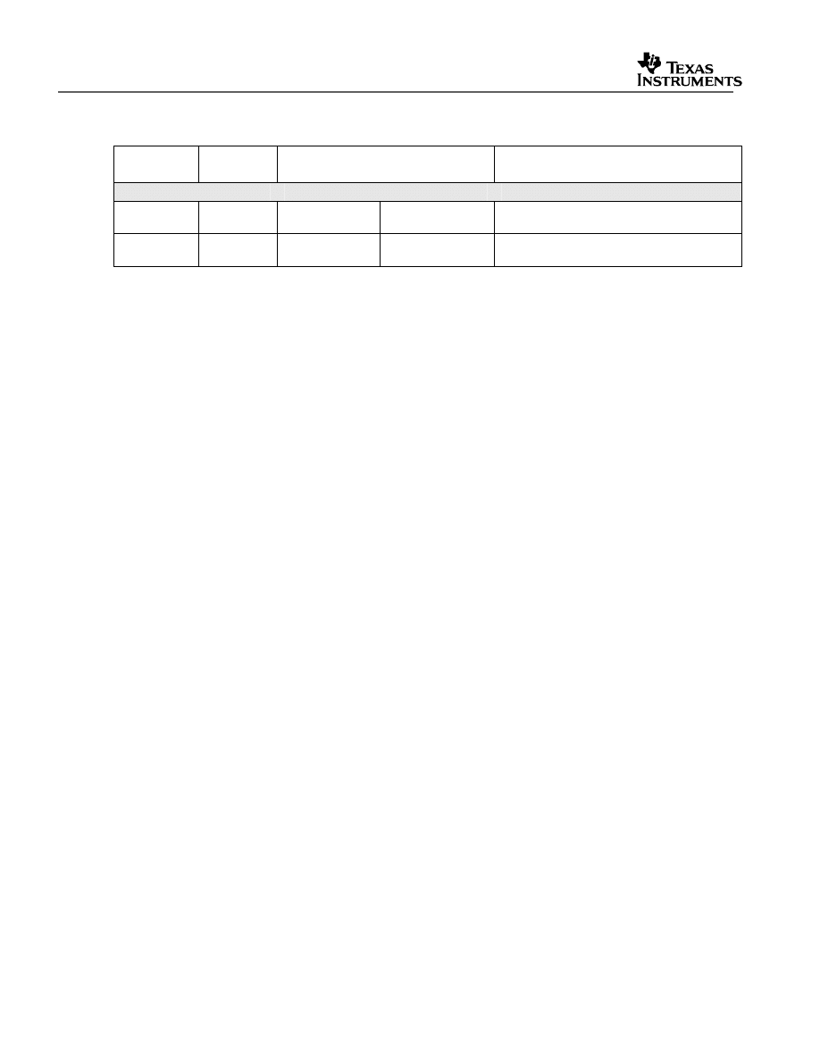
V1.30 Quick Start Readme
44
Table 10. Summary of Register and Bit-Name Changes from DSP280x V1.41 to
DSP2833x V1.01
Bit Name
Peripheral
Register
Old
New
Comment
SysCtrlRegs
XCLK
Register removed because XCLKOUT is
controlled by XINTF now.
PLLSTS
CLKINDIV(bit 1)
DIVSEL (bits 8,7)
DIVSEL allows more values by which
CLKIN can be divided.
If migrating from the TMS320x281x header files, most of these changes will fall into one
of the following categories:
-
Bit-name or register name corrections to align with the peripheral user guides. See
Table 11 for a listing of these changes.
-
Code that was written for the 281x event manager (EV) will need to be re-written for
the 2833x/2823x ePWM, eCAP and eQEP peripherals.
-
Code for the 281x McBSP will need to be modified for the 2833x/2823x version of the
peripheral (FIFO replaced with DMA).
Code for the 281x XINTF will need to be modified for the 2833x/2823x version of the
peripheral in the following ways:
-
The .cmd linker file will need to be updated because zone memory locations have
changed and the 2833x/2823x only has Zones 0, 6, and 7.
-
Because both the boot ROM and the XINTF zones are always memory-mapped on
the 2833x, there is no longer any need for the MPNMC bit in the XINTCNF2
registers. Therefore, the MPNMC bit on the 281x is now reserved on the
2833x/2823x. See Table 11.
-
On the 281x, the clock to the XINTF was always enabled. On the 2833x/2823x, code
must be added which will enable/disable the clock to the XINTF module in the
PCLKCR3 system control register.
-
Because the XINTF pins on the 2833x/2823x are now MUX’d with GPIO pins at
reset, code migrating from the 281x to the 2833x/2823x will need to modify the
XINTF initialization to enable the GPIO pins for XINTF mode.
-
There is now an XRESET register on the 2833x/2823x which was not available on
the 281x.
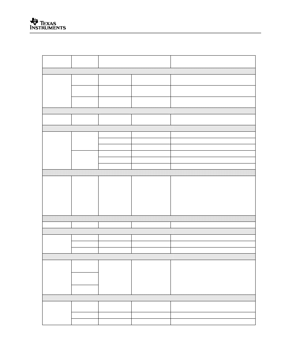
V1.20 Quick Start Readme
45
Table 11. Summary of Register and Bit-Name Changes from DSP281x V1.00 to
DSP2833x V1.01
Bit Name
Peripheral
Register
Old
New
Comment
AdcRegs
ADCTRL2
EVB_SOC_
SEQ2
EPWM_SOCB_
SEQ2
SOC is now performed by ePWM
EVA_SOC_
SEQ1
EPWM_SOCA_
SEQ1
SOC is now performed by ePWM
EVB_SOC_
SEQ
EPWM_SOCB_
SEQ
SOC is now performed by ePWM
DevEmuRegs
DEVICEID
PARTID
REVID
Split into two registers, PARTID and REVID
EcanaRegs
CANMDL
BYTE1
BYTE3
Order of bytes was incorrect
BYTE3
BYTE1
BYTE4
BYTE0
CANMDH
BYTE5
BYTE7
Order of bytes was incorrect
BYTE7
BYTE5
BYTE8
BYTE4
GpioMuxRegs
The GPIO peripheral has been redesigned
from the 281x. All of the registers have
moved from 16-bit to 32-bits. The
GpioMuxRegs are now the GpioCtrlRegs
and the bit definitions have all changed.
Please refer to TMS320x2833x Control and
Interrupts Reference Guide for more
information on the GPIO peripheral.
PieCtrlRegs
PIECTRL
PIECRTL
PIECTRL
Typo
SciaRegs, ScibRegs
SCIFFTX
TXFFILIL
TXFFIL
Typo
TXINTCLR
TXFFINTCLR
Alignment with user’s guide.
SCIFFRX
RXFIFST
RXFFST
Typo – Also corrected in user’s guide
McbspaRegs
MFFTX
MFFRX
MFFCT
The McBSP FIFO on the 281x has been
removed and replaced by the DMA.
Therefore these FIFO registers do not exist
on the 2833x. Please refer to the
TMS320x2833x McBSP Reference Guide
for more information on the McBSP
peripheral.
XintfRegs
XINTCNF2
MPNMC
Rsvd2
The MPNMC bit does not exist on the
2833x
XTIMING1
There is no Zone 1 on the 2833x
XTIMING2
There is no Zone 2 on the 2833x
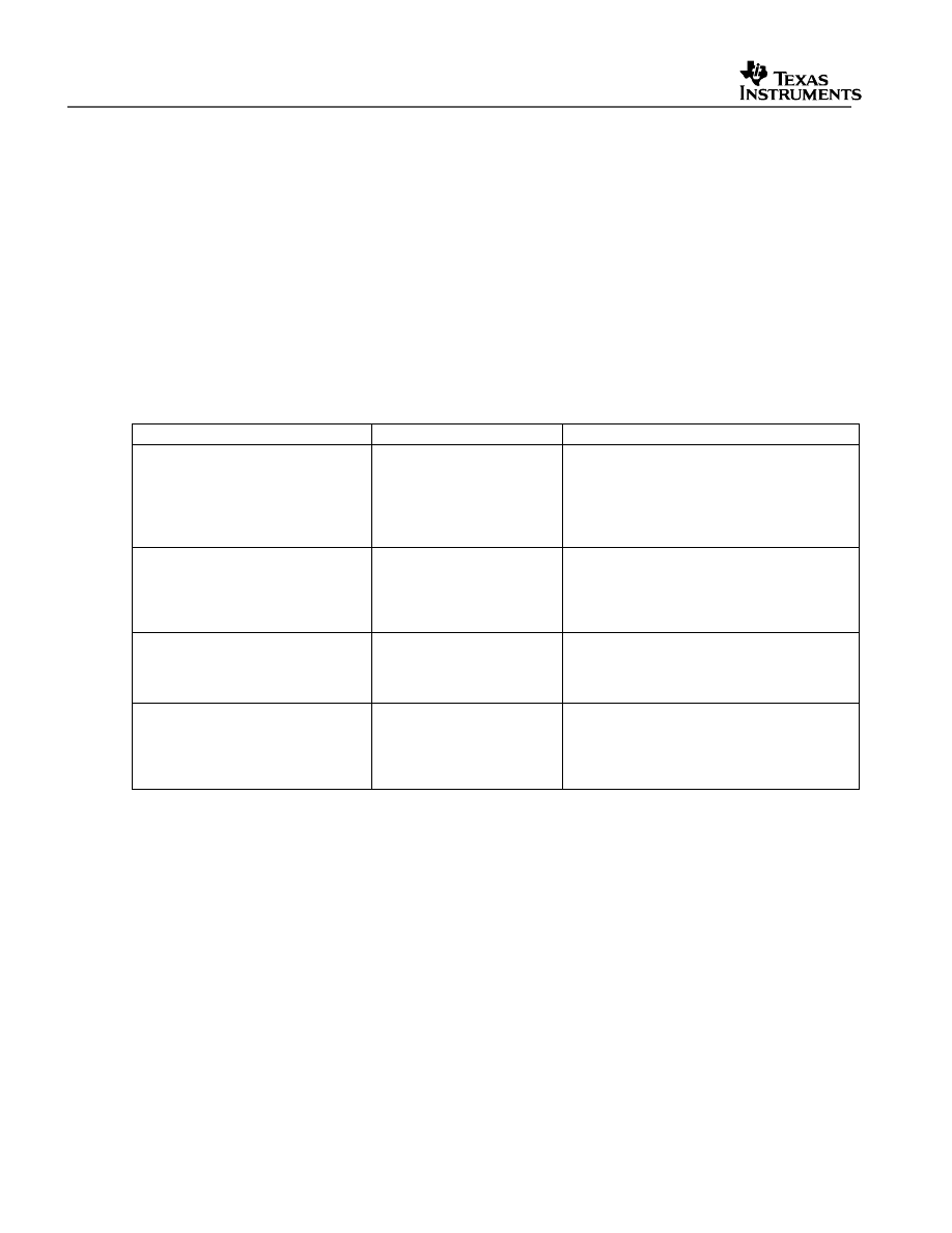
V1.30 Quick Start Readme
46
8 Packet Contents:
This section lists all of the files included in the release.
8.1 Header File Support – DSP2833x_headers
The DSP2833x header files are located in the <base>\DSP2833x_headers\ directory.
8.1.1 DSP2833x Header Files – Main Files
The following files must be added to any project that uses the DSP2833x header files. Refer
to section 5.2 for information on incorporating the header files into a new or existing project.
Table 12. DSP2833x Header Files – Main Files
File
Location
Description
DSP2833x_Device.h
DSP2833x_headers\include Main include file. Include this one file in any
of your .c source files. This file in-turn
includes all of the peripheral specific .h files
listed below. In addition the file includes
typedef statements and commonly used
mask values. Refer to section 5.2.
DSP2833x_GlobalVariableDefs.c
DSP2833x_headers\source
Defines the variables that are used to access
the peripheral structures and data section
#pragma assignment statements. This file
must be included in any project that uses the
header files. Refer to section 5.2.
DSP2833x_Headers_BIOS.cmd
DSP2833x_headers\cmd
Linker .cmd file to assign the header file
variables in a BIOS project. This file must
be included in any BIOS project that uses
the header files. Refer to section 5.2.
DSP2833x_Headers_nonBIOS.cmd DSP2833x_headers\cmd
Linker .cmd file to assign the header file
variables in a non-BIOS project. This file
must be included in any non-BIOS project
that uses the header files. Refer to section
5.2.
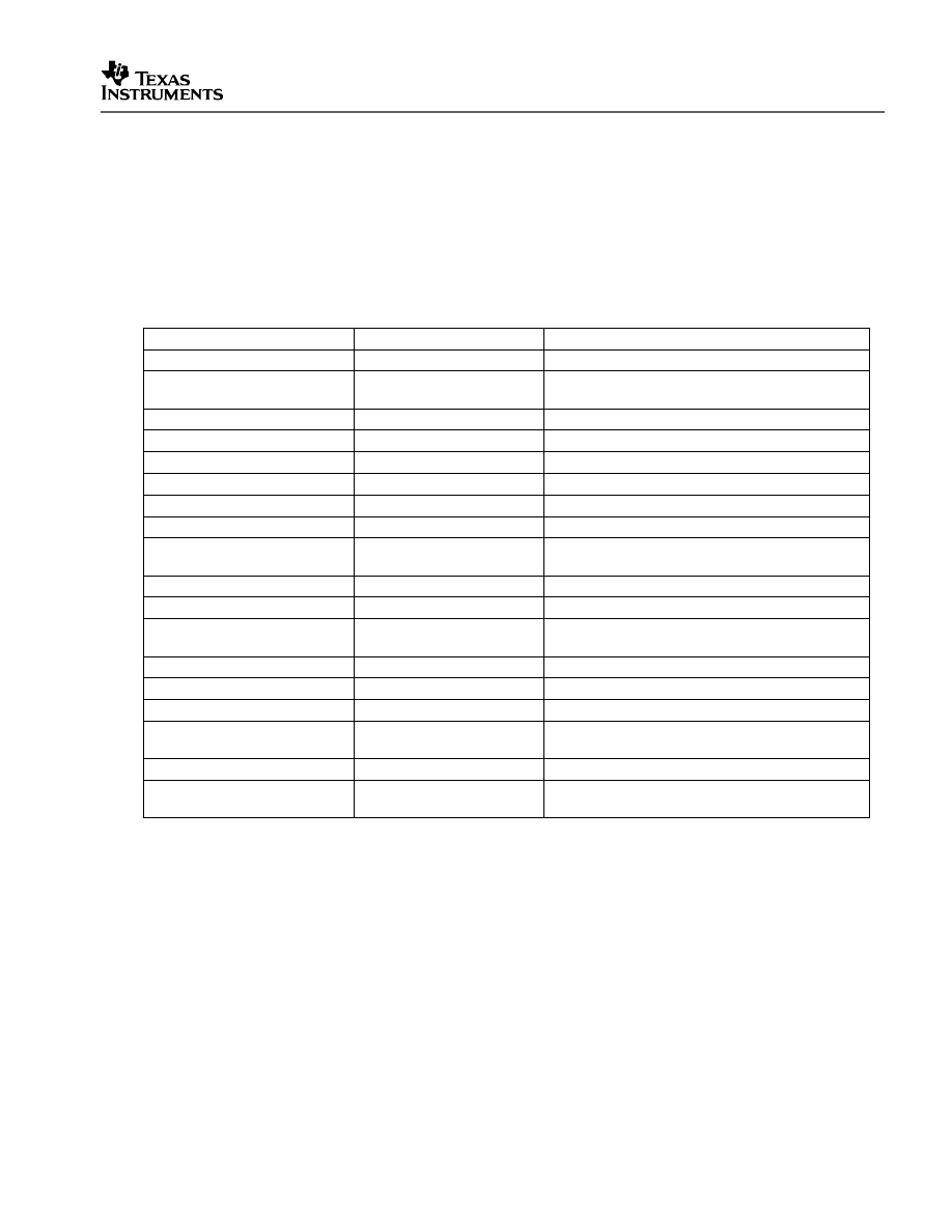
V1.20 Quick Start Readme
47
8.1.2 DSP2833x Header Files – Peripheral Bit-Field and Register Structure Definition
Files
The following files define the bit-fields and register structures for each of the peripherals on
the 2833x devices. These files are automatically included in the project by including
DSP2833x_Device.h. Refer to section 4.2 for more information on incorporating the header
files into a new or existing project.
Table 13. DSP2833x Header File Bit-Field & Register Structure Definition Files
File
Location
Description
DSP2833x_Adc.h
DSP2833x_headers\include ADC register structure and bit-field definitions.
DSP2833x_CpuTimers.h
DSP2833x_headers\include CPU-Timer register structure and bit-field
definitions.
DSP2833x_DevEmu.h
DSP2833x_headers\include Emulation register definitions
DSP2833x_DMA.h
DSP2833x_headers\include DMA register structures and bit-field definitions.
DSP2833x_ECan.h
DSP2833x_headers\include eCAN register structures and bit-field definitions.
DSP2833x_ECap.h
DSP2833x_headers\include eCAP register structures and bit-field definitions.
DSP2833x_EPwm.h
DSP2833x_headers\include ePWM register structures and bit-field definitions.
DSP2833x_EQep.h
DSP2833x_headers\include eQEP register structures and bit-field definitions.
DSP2833x_Gpio.h
DSP2833x_headers\include General Purpose I/O (GPIO) register structures
and bit-field definitions.
DSP2833x_I2c.h
DSP2833x_headers\include I2C register structure and bit-field definitions.
DSP2833x_Mcbsp.h
DSP2833x_headers\include McBSP register structure and bit-field definitions.
DSP2833x_PieCtrl.h
DSP2833x_headers\include PIE control register structure and bit-field
definitions.
DSP2833x_PieVect.h
DSP2833x_headers\include Structure definition for the entire PIE vector table.
DSP2833x_Sci.h
DSP2833x_headers\include SCI register structure and bit-field definitions.
DSP2833x_Spi.h
DSP2833x_headers\include SPI register structure and bit-field definitions.
DSP2833x_SysCtrl.h
DSP2833x_headers\include System register definitions. Includes Watchdog,
PLL, CSM, Flash/OTP, Clock registers.
DSP2833x_Xintf.h
DSP2833x_headers\include XINTF register structure and bit-field definitions.
DSP2833x_XIntrupt.h
DSP2833x_headers\include External interrupt register structure and bit-field
definitions.
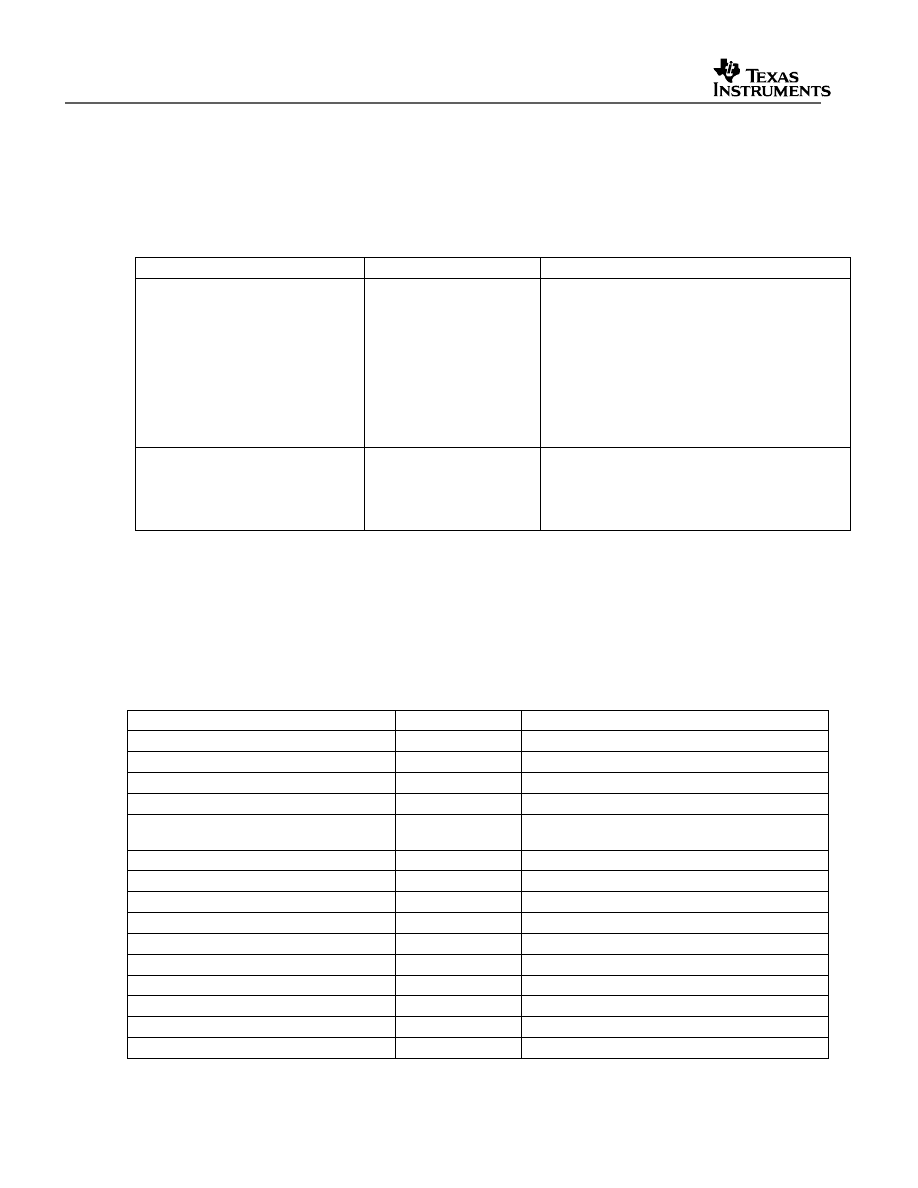
V1.30 Quick Start Readme
48
8.1.3 Code Composer .gel Files
The following Code Composer Studio .gel files are included for use with the DSP2833x
Header File peripheral register structures.
Table 14. DSP2833x Included GEL Files
File
Location
Description
DSP2833x_Peripheral.gel
DSP2833x_headers\gel
This is relevant for CCSv3.3 only.
Provides GEL pull-down menus to load the
DSP2833x data structures into the watch
window.
You may want to have CCS load this file
automatically by adding a
GEL_LoadGel(“<base>DSP2833x_headers\/gel\
DSP2833x_peripheral.gel”) function to the
standard F28335.gel that was included with
CCS.
DSP2833x_DualMap_EPWM.gel
DSP2833x_headers\gel
Provides GEL pull-down menus to enable
EPWM dual-map mode on device (re-maps
EPWM registers to allow DMA access to EPWM
registers), and loads DSP2833x dual-mapped
EPWM data structures into the watch window.
8.1.4 Variable Names and Data Sections
This section is a summary of the variable names and data sections allocated by the
DSP2833x_headers\source\DSP2833x_GlobalVariableDefs.c file. Note that all peripherals
may not be available on a particular 2833x device. Refer to the device datasheet for the
peripheral mix available on each 2833x family derivative.
Table 15. DSP2833x Variable Names and Data Sections
Peripheral
Starting Address
Structure Variable Name
ADC
0x007100
AdcRegs
ADC Mirrored Result Registers
0x000B00
AdcMirror
ADC Calibration Value Locations
0x380083
AdcCalVal
Code Security Module
0x000AE0
CsmRegs
Code Security Module Password
Locations
0x33FFF8-
0x33FFFF
CsmPwl
CPU Timer 0
0x000C00
CpuTimer0Regs
Device and Emulation Registers
0x000880
DevEmuRegs
DMA Registers
0x001000
DmaRegs
eCAN-A
0x006000
ECanaRegs
eCAN-A Mail Boxes
0x006100
ECanaMboxes
eCAN-A Local Acceptance Masks
0x006040
ECanaLAMRegs
eCAN-A Message Object Time Stamps
0x006080
ECanaMOTSRegs
eCAN-A Message Object Time-Out
0x0060C0
ECanaMOTORegs
eCAN-B
0x006200
ECanbRegs
eCAN-B Mail Boxes
0x006300
ECanbMboxes
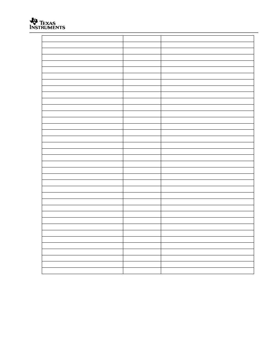
V1.20 Quick Start Readme
49
eCAN-B Local Acceptance Masks
0x006240
ECanbLAMRegs
Peripheral
Starting Address
Structure Variable Name
eCAN-B Message Object Time Stamps
0x006280
ECanbMOTSRegs
eCAN-B Message Object Time-Out
0x0062C0
ECanbMOTORegs
ePWM1
0x006800
EPwm1Regs
ePWM2
0x006840
EPwm2Regs
ePWM3
0x006880
EPwm3Regs
ePWM4
0x0068C0
EPwm4Regs
ePWM5
0x006900
EPwm5Regs
ePWM6
0x006940
EPwm6Regs
ePWM1 (dual-mapped)
0x005800
EPwm1Regs
ePWM2 (dual-mapped)
0x005840
EPwm2Regs
ePWM3 (dual-mapped)
0x005880
EPwm3Regs
ePWM4 (dual-mapped)
0x0058C0
EPwm4Regs
ePWM5 (dual-mapped)
0x005900
EPwm5Regs
ePWM6 (dual-mapped)
0x005940
EPwm6Regs
eCAP1
0x006A00
ECap1Regs
eCAP2
0x006A20
ECap2Regs
eCAP3
0x006A40
ECap3Regs
eCAP4
0x006A60
ECap4Regs
eCAP5
0x006A80
ECap5Regs
eCAP6
0x006AA0
ECap6Regs
eQEP1
0x006B00
EQep1Regs
eQEP2
0x006B40
EQep2Regs
External Interrupt Registers
0x007070,
XIntruptRegs
Flash & OTP Configuration Registers
0x000A80
FlashRegs
General Purpose I/O Data Registers
0x006fC0
GpioDataRegs
General Purpose Control Registers
0x006F80
GpioCtrlRegs
General Purpose Interrupt Registers
0x006fE0
GpioIntRegs
I2C
0x007900
I2caRegs
McBSP-A
0x005000
McbspaRegs
McBSP-B
0x005040
McbspbRegs
PIE Control
0x000CE0
PieCtrlRegs
SCI-A
0x007050
SciaRegs
SCI-B
0x007750
ScibRegs
SCI-C
0x007770
ScicRegs
SPI-A
0x007040
SpiaRegs
XINTF
0x000B20
XintfRegs
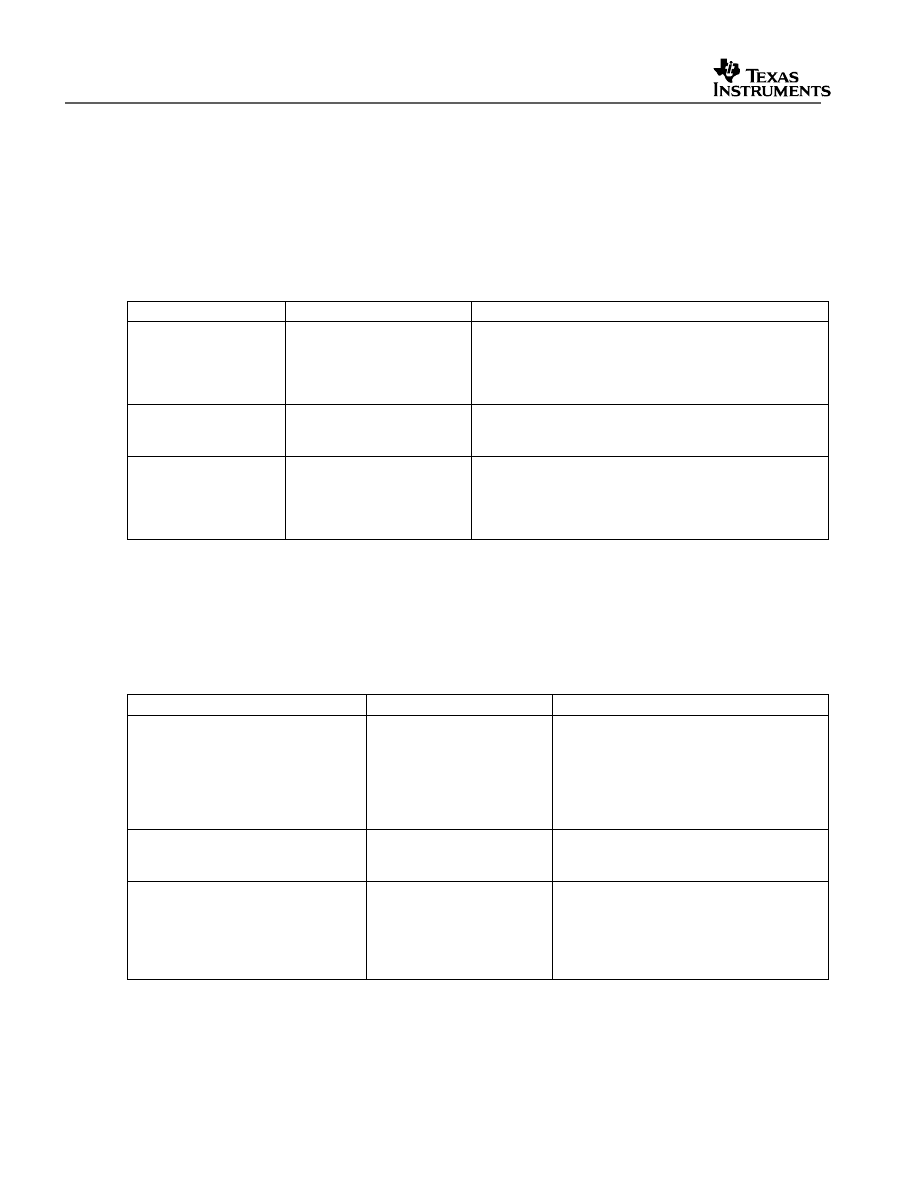
V1.30 Quick Start Readme
50
8.2 Common Example Code – DSP2833x_common
8.2.1 Peripheral Interrupt Expansion (PIE) Block Support
In addition to the register definitions defined in DSP2833x_PieCtrl.h, this packet provides the
basic ISR structure for the PIE block. These files are:
Table 16. Basic PIE Block Specific Support Files
File
Location
Description
DSP2833x_DefaultIsr.c DSP2833x_common\source
Shell interrupt service routines (ISRs) for the entire PIE
vector table. You can choose to populate one of
functions or re-map your own ISR to the PIE vector
table.
Note: This file is not used for DSP/BIOS
projects.
DSP2833x_DefaultIsr.h DSP2833x_common\include Function prototype statements for the ISRs in
DSP2833x_DefaultIsr.c.
Note: This file is not used for
DSP/BIOS projects.
DSP2833x_PieVect.c
DSP2833x_common\source
Creates an instance of the PIE vector table structure
initialized with pointers to the ISR functions in
DSP2833x_DefaultIsr.c. This instance can be copied to
the PIE vector table in order to initialize it with the default
ISR locations.
In addition, the following files are included for software prioritization of interrupts. These files
are used in place of those above when additional software prioritization of the interrupts is
required. Refer to the example and documentation in
DSP2833x_examples\sw_prioritized_interrupts for more information.
Table 17. Software Prioritized Interrupt PIE Block Specific Support Files
File
Location
Description
DSP2833x_SWPrioritizedDefaultIsr.c DSP2833x_common\source
Default shell interrupt service routines
(ISRs). These are shell ISRs for all of the
PIE interrupts. You can choose to
populate one of functions or re-map your
own interrupt service routine to the PIE
vector table.
Note: This file is not used
for DSP/BIOS projects.
DSP2833x_SWPrioritizedIsrLevels.h
DSP2833x_common\include Function prototype statements for the ISRs
in DSP2833x_DefaultIsr.c.
Note: This file
is not used for DSP/BIOS projects.
DSP2833x_SWPrioritizedPieVect.c
DSP2833x_common\source
Creates an instance of the PIE vector table
structure initialized with pointers to the
default ISR functions that are included in
DSP2833x_DefaultIsr.c. This instance can
be copied to the PIE vector table in order
to initialize it with the default ISR locations.
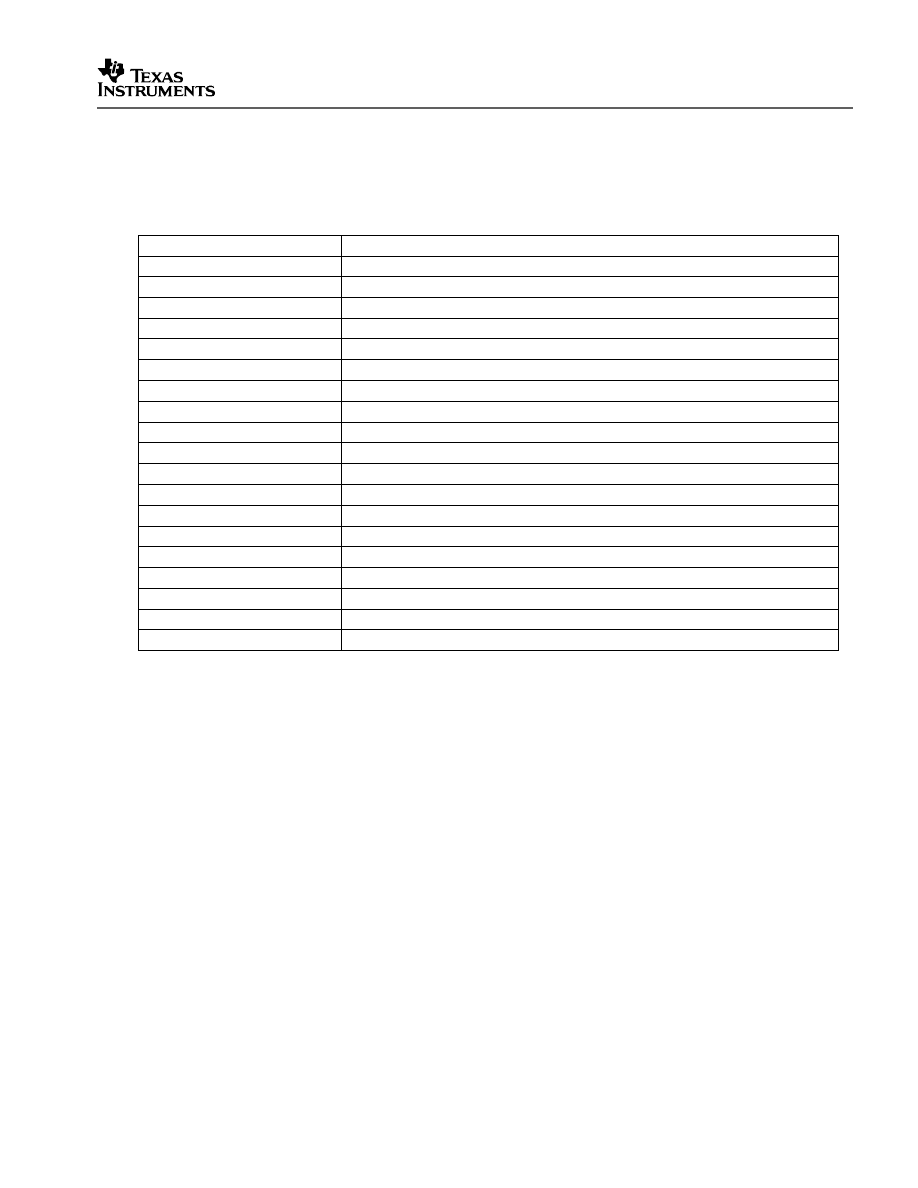
V1.20 Quick Start Readme
51
8.2.2 Peripheral Specific Files
Several peripheral specific initialization routines and support functions are included in the
peripheral .c source files in the DSP2833x_common\src\ directory. These files include:
Table 18. Included Peripheral Specific Files
File
Description
DSP2833x_GlobalPrototypes.h Function prototypes for the peripheral specific functions included in these files.
DSP2833x_Adc.c
ADC specific functions and macros.
DSP2833x_CpuTimers.c
CPU-Timer specific functions and macros.
DSP2833x_DMA.c
DMA specific functions and macros.
DSP2833x_Dma_defines.h
#define macros that are used for the DMA examples.
DSP2833x_ECan.c
Enhanced CAN specific functions and macros.
DSP2833x_ECap.c
eCAP module specific functions and macros.
DSP2833x_EPwm.c
ePWM module specific functions and macros.
DSP2833x_EPwm_defines.h
#define macros that are used for the ePWM examples
DSP2833x_EQep.c
eQEP module specific functions and macros.
DSP2833x_Gpio.c
General-purpose IO (GPIO) specific functions and macros.
DSP2833x_I2C.c
I2C specific functions and macros.
DSP2833x_I2c_defines.h
#define macros that are used for the I2C examples
DSP2833x_Mcbsp.c
McBSP specific functions and macros.
DSP2833x_PieCtrl.c
PIE control specific functions and macros.
DSP2833x_Sci.c
SCI specific functions and macros.
DSP2833x_Spi.c
SPI specific functions and macros.
DSP2833x_SysCtrl.c
System control (watchdog, clock, PLL etc) specific functions and macros.
DSP2833x_Xintf.c
XINTF specific functions and macros.
Note:
The specific routines are under development and may not all be available as of this release. They will be
added and distributed as more examples are developed.
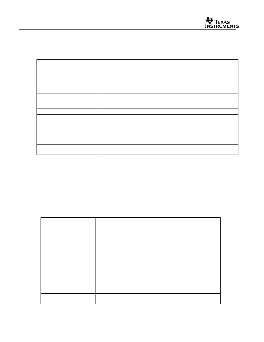
V1.30 Quick Start Readme
52
8.2.3 Utility Function Source Files
Table 19. Included Utility Function Source Files
File
Description
DSP2833x_ADC_cal.asm
Includes the ADC_cal function, which is pre-programmed into reserved TI
OTP. This function, which copies device-specific calibration data into the
ADCREFSEL and ADCOFFTRIM registers, is normally called in the boot
ROM. When debugging though, if the boot ROM is bypassed, it is necessary
to call this function after enabling the clocks to the ADC in order to use the
ADC module.
DSP2833x_CodeStartBranch.asm
Branch to the start of code execution. This is used to re-direct code
execution when booting to Flash, OTP or M0 SARAM memory. An option to
disable the watchdog before the C init routine is included.
DSP2833x_DBGIER.asm
Assembly function to manipulate the DEBIER register from C.
DSP2833x_DisInt.asm
Disable interrupt and restore interrupt functions. These functions allow you
to disable INTM and DBGM and then later restore their state.
DSP2833x_usDelay.asm
Assembly function to insert a delay time in microseconds. This function is
cycle dependant and must be executed from zero wait-stated RAM to be
accurate.
Refer to DSP2833x_examples\adc for an example of its use.
DSP2833x_CSMPasswords.asm
Include in a project to program the code security module passwords and
reserved locations.
8.2.4 Example Linker .cmd files
Example memory linker command files are located in the DSP2833x_common\cmd directory.
For getting started the basic 28335_eZdsp_RAM_lnk.cmd file is suggested and used by
many of the included examples.
The SARAM blocks L0, L1, L2, and L3 are mirrored on these devices. For simplicity these
memory maps only include one instance of these memory blocks.
Table 20. Included Main Linker Command Files
Memory Linker Command
File Examples
Location
Description
28335_RAM_lnk.cmd
DSP2833x_common\cmd 28335/28235 memory linker command
file. Includes all of the internal SARAM
blocks on a 28335/28235 device. “RAM”
linker files do not include flash or OTP
28334_RAM_lnk.cmd
DSP2833x_common\cmd 28334/28234 SARAM memory linker
command file.
28332_RAM_lnk.cmd
DSP2833x_common\cmd 28332/28232 SARAM memory linker
command file.
F28335.cmd
DSP2833x_common\cmd F28335/F28235 memory linker command
file. Includes all Flash, OTP and CSM
password protected memory locations.
F28334.cmd
DSP2833x_common\cmd F28334/F28234 memory linker command
file.
F28332.cmd
DSP2833x_common\cmd F28332/ F28232 memory linker
command file.
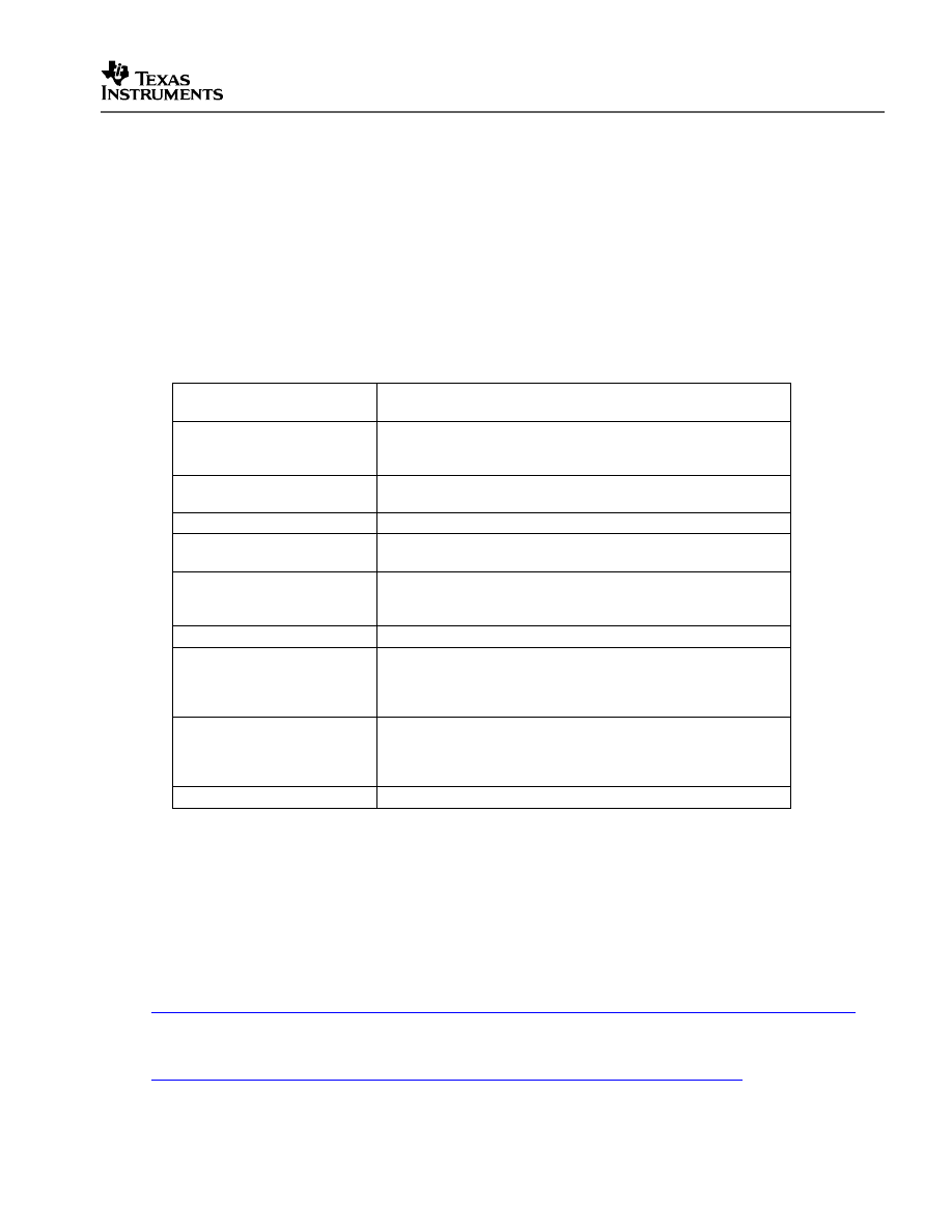
V1.20 Quick Start Readme
53
8.2.5 Example Library .lib Files
Example library files are located in the DSP2833x_common\lib directory. For this release the
IQMath library is included for use in the example projects. Please refer to the C28x IQMath
Library - A Virtual Floating Point Engine (SPRC087) for more information on IQMath and the
most recent IQMath library. The SFO libraries are also included for use in the example
projects. Please refer to TMS320x28xx, 28xxx HRPWM Reference Guide (SPRU924) for
more information on SFO library usage and the HRPWM module.
Table 21. Included Library Files
Main Liner Command File
Examples
Description
IQmath.lib
Please refer to the C28x IQMath Library - A Virtual Floating
Point Engine (SPRC087) for more information on IQMath. This
is a fixed-point compiled library.
IQmath_fpu32.lib
The floating-point equivalent of IQmath.lib. See Section 4.6 for
information about including fixed and floating point libraries.
IQmathLib.h
IQMath header file.
SFO_TI_Build.lib
Please refer to the TMS320x28xx, 28xxx HRPWM Reference
Guide (SPRU924) for more information on the SFO library
SFO_TI_Build_fpu.lib
The floating-point equivalent of SFO_TI_Build.lib. See Section
4.6 for information about including fixed and floating point
libraries.
SFO.h
SFO header file
SFO_TI_Build_V5.lib/
SFO_TI_Build_V5B.lib
Please refer to the TMS320x28xx,28xxx HRPWM Reference
Guide (SPRU924) for more information on the SFO V5 library.
Updated versions will be marked with alphabetical characters
after “V5” (i.e. SFO_TI_Build_V5B.lib)
SFO_TI_Build_V5_fpu.lib/
SFO_TI_Build_V5B_fpu.lib
The floating-point equivalent of SFO_TI_Build_V5.lib. See
Section 4.6 for information about including fixed and floating
point libraries. Updated versions will be marked with
alphabetical characters after “V5” (i.e. SFO_TI_Build_V5B.lib)
SFO_V5.h
SFO V5 header file
9 Migrating Projects from Code Composer Studio v3.x to Code
Composer Studio 4.0
This document does not discuss Code Composer Studio specifics. For more information on
project migration from CCStudio v3.x to CCStudio v4, visit the online C2000 Code
Comoposer Studio v4 wiki at:
http://tiexpressdsp.com/index.php/C2000_Getting_Started_with_Code_Composer_Studio_v4
Or visit the online Code Composer Studio v4 wiki at:
http://tiexpressdsp.com/index.php?title=Category:Code_Composer_Studio_v4

V1.30 Quick Start Readme
54
10 Detailed Revision History:
Changes from V1.30 to V1.31
Changes to Example Files:
a)
All PJT Files - Removed the line: Tool="DspBiosBuilder" from all example PJT files
for easy migration path to CCSv4 Microcontroller-only (code-size limited) version
users.
Changes from V1.20 to V1.30
Changes to Header Files:
b)
DSP2833x_DevEmu.h– Removed non-existent bits from DEVICECNF register.
c)
DSP2833x_Headers_BIOS.cmd- Changed CSM_PWL from 0x3F7FF8 to 0x33FFF8
d)
DSP2833x_Xintf.h- Fixed XRESET register so that it uses XRESET bit structure
instead of XBANK bi structure.
Changes to Common Files:
e)
DSP2833x_SysCtrl.c– Added comment indicating DIVSEL = divide by 1 mode is
valid only when PLL is bypassed.
f)
2833x_RAM_lnk.cmd, F2833x.cmd – In all common device command linker files,
BOOT_RSVD was moved from PAGE0 to PAGE1 data space.
g)
2833x.gel- In all device gel files, XINTF_Enable function call was removed from
OnFilePreloaded() function, but function itself remains in the gel files.
h)
Added /DSP2833x_common/gel/ccsv4/ directory- Because CCSv4.0 does not
support the “WatchAdd()” gel command, new device gels without any “WatchAdd()”
entries have been generated for CCSv4.0. These are located in the /ccsv4/ directory.
i)
DSP2833x_CpuTimers.c- Modified comments – CPUTimer 2 is reserved for use by
DSP/BIOS. When using DSP/BIOS, all CPUTimer 2 code should be commented out.
Changes to Example Files:
a)
Example_2833xMcBSP_DLB.pjt, Example_2833xMcBSP_DLB_DMA.pjt,
Example_2833xMcBSP_DLB_int.pjt, Example_2833xMcBSP_SPI_DLB.pjt–
Changed McBSP.c to Mcbsp.c. There is no McBSP.c file in the
/DSP2833x_common/source/ directory. When migration projects from CCSv3.3 to
CCSv4.0, CCSv4.0 is case-sensitive.
b)
Example_2833xHaltWake.c – Updated Description comments concerning halt
wakeup procedure using GPIO0.

V1.20 Quick Start Readme
55
c)
Added DSP2833x_examples_ccsv4 and DSP2823x_examples_ccsv4 directories
- Added directories for CCSv4.x projects. The example projects in these directories
are identical to those found in the normal CCSv3.x DSP2833x_examples and
DSP2823x_examples directories with the exception that the examples now support
the Code Composer Studio v4.x project folder format instead of the Code Composer
Studio v3.x PJT files. The example gel files have also been removed for the CCSv4
example projects because the gel file functions used in the example gels are no
longer supported.
Changes from V1.10 to V1.20
Changes to Header Files:
a)
DSP2833x_Spi.h– Changed SPIPRI register bit 6 to “rsvd” to match SPI Reference
Guide.
b)
DSP2833x_DualMap_EPWM.gel - added this gel file, which enables dual-mapping of
EPWM registers to DMA-accessible memory (registers are re-mapped), and creates
GEL pull-down menus which add re-mapped registers to watch window (applicable for
‘2833x/’2823x silicon Rev.A and later).
c)
DSP2833x_Mcbsp.h – In MFFINT register, changed bits 1 and 3 to “rsvd” to match
McBSP Reference Guide.
d)
DSP2833x_DevEmu.h – Current PARTID register moved to OTP at 0x380090. New
structure called PartIdRegs with 1 register, PARTID, created (identical to register
previously located at 0x882 as part of DevEmuRegs). At address 0x882 (previously
PARTID register), created new register, CLASSID, with two fields – CLASSNO and
PARTTYPE. CLASSNO indicates whether device is floating-point or fixed-point.
PARTTYPE is identical to PARTTYPE field in PARTID register.
e)
DSP2833x_Dma.h – Added comments to include EPWM SOC signals as DMA
triggers.
f)
DSP2833x_GlobalPrototypes.c – Added PartIdRegs entry for new register structure.
g)
DSP2833x_Headers_nonBIOS.cmd, DSP2833x_Headers_BIOS.cmd – Added
PARTID memory location in OTP at 0x380090 (1 16-bit word) and added Section to
place PartIdRegs structure in PARTID memory location.
Changes to Common Files:
h)
DSP2833x_GlobalPrototypes.h– Added delay_loop() prototype for function used in
DSP2833x_Mcbsp.c.
i)
DSP280x_I2c_defines.h – Fixed typo: I2C_DEINFES changed to I2C_DEFINES.
j)
DSP2833x_ECan.c – Updated baud rate frequencies to account for CANCLK =
SYSCLK/2. Removed bit configuration comments at end of file. Added disclaimer –
bit timings in source file are suggested timings only. They may vary with different
system settings and user environment.

V1.30 Quick Start Readme
56
k)
DSP2833x_Dma.c – In DMAInitialize() function, added one NOP after HARDRESET
bit is set to align with DMA reference guide requirement.
l)
f28235.gel, f28234.gel, and f28232.gel – Added 2823x gel files, which are identical
copies of 28335.gel, 28334.gel, and 28332.gel with the exception that FPU registers
are removed. Also added C28x_Mode() function call to OnRestart(), OnReset(), and
OnTargetConnect() functions so that device is always configured for C28x addressing
mode when debugging.
m)
f28335.gel, f28334.gel, and f28332.gel – Added C28x_Mode() function call to
OnRestart(), OnReset(), and OnTargetConnect() functions so that device is always
configured for C28x addressing mode when debugging.
n)
DSP2833x_Examples.h – Added part #’s for 28235, 28234, and 28232, and changed
part #’s for 28335, 28334, 28332 in accordance to new PARTID’s for Indus Rev. A.
o)
IQmathLib.h- New IQmath header files to be used with V1.5 of IQmath.lib and
IQmath_fpu32.lib libraries.
p)
IQmath.lib and IQmath_fpu32.lib – Added version 1.5 of IQ math libraries (fixed and
floating-point compiled versions) replaces old Version 1.4.
q)
F28335.cmd, F28334.cmd, F28332.cmd, 28335_RAM_lnk.cmd,
28334_RAM_lnk.cmd, 28332_RAM_lnk.cmd – Commented out IQmathTables2
section with segment that indicates only IQNexpTable is loaded into Boot ROM (doing
so eliminates linker errors if IQNexp() or IQexp() functions are not called in code).
Changes to Example Files:
r)
Example_2833xEPwm_DMA.c, Example_2833xEPwm_DMA.pjt,
Example_2833xEPwm_DMA.gel, DSP2833x_EPWMDM_Headers_BIOS.cmd,
DSP2833x_EPWMDM_Headers_nonBIOS.cmd (and 2823x versions) – Added new
example (in epwm_dma folder of DSP2833x_examples and DSP2823x_examples
directories) which demonstrates dual-mapping of EPWM registers (registers re-
mapped to DMA-accessible memory locations starting at 0x5800 instead of 0x6800)
and DMA triggered by EPWM SOC signals.
s)
Example_2833xHRPWM_slider.c (and 2823x version)- Set EPwm1Regs.TBPRD =
period - 1; so that initial duty cycle is truly 50% % (TB counter counts from 0 to period-
1 for a total of “period” counts).
t)
Example2833x_HRPWM.c – Set EPwm1Regs.TBPRD = period - 1; so that initial duty
cycle is truly 50% (TB counter counts from 0 to period-1 for a total of “period” counts).
u)
Example_2833xHRPWM_SFO_V5.c (and 2823x version) – Added code to enable
HRPWM logic prior to calling SFO_MepDis_V5().
v)
Example_freqcal.xls (eqep_freqcal)– description of UPPS bit settings has been
corrected.
w)
Example_2833xCodeRunFromXintf.c (and 2823x version) – added #if directives
for setting up CPU Timer frequency for both 150 MHz and 100 MHz options.

V1.20 Quick Start Readme
57
x)
Example_2833xHaltWake.c (and 2823x version) – removed “return” statement at
end of ISR and changed GPASET to GPATOGGLE for GPIO1 in ISR.
y)
Various examples (dma_ram_to_ram, mcbsp_loopback, mcbsp_spi_loopback,
sci_loopback, and all lpm examples)- changed “while(1) to for(;;) to eliminate compiler
warnings.
z)
Example_2833xMcBSP_DLB.c (and 2823x version)– Cleaned up example to
eliminate compiler warnings.
aa)
Example_2833xMcBSP_DLB_DMA.c (and 2823x version)– Cleaned up example to
eliminate compiler warnings.
bb)
Example_2833xCodeRunFromXintf.c (and 2823x version)- Added CPU Timer
configuration for 150 MHz SYSCLK (previously only 100 MHz SYSCLK configuration).
cc)
Example_2833xEqep_freqcal.pjt and Example_2833xEqep_freqcal.pjt – Modified
build options to build with fpu enabled (now that fpu32-compiled IQmath_fpu32.lib
library is available).
Changes from V1.03 to V1.10
Changes to Header Files:
a)
DSP2833x_Peripheral.gel– Collapsed eCAN register submenus into one submenu
each for eCAN-A and eCAN-B to reduce GEL submenu size (reaching Code
Composer Studio limit)
b)
DSP2833x_Device.h- added types for int64 and Uint64.
c)
DSP2833x_Headers_BIOS.cmd and DSP2833x_Headers_nonBIOS.cmd – Fixed
comments – “DMA Rev. 0” changed to “DMA”.
Changes to Common Files:
d)
DSP2833x_SWPrioritizedDefaultIsr.c and DSP2833x_DefaultIsr.c – Removed
references to EMPTY_ISR(). The function is not used in any other file in header file
directory structure.
e)
f28335.gel, f28334.gel, and f28332.gel – Collapsed several GEL submenus,
removed code which adds FPU registers to watch window upon connect, modified
important messages to appear only once upon file preload, and configured gel to
display an error message only when ADC not properly calibrated.
Changes to Example Files:
f)
DSP2823x_examples - Added DSP2823x_examples folder with all of the same
examples as DSP2833x_examples (minus fpu) compiled with fixed-point code instead
of floating-point code because DSP2823x devices do not have an FPU.
g)
Example2833x_SWPrioritizedDefaultIsr.c – Removed reference to EMPTY_ISR().
The function is not used in any other file in header file directory structure.

V1.30 Quick Start Readme
58
Changes from V1.02 to V1.03
Changes to Header Files:
a)
DSP2833x_Headers_Bios.cmd – Added sections for ECAP5/ECAP6 and removed
SECTIONS definition for PIE_VECT.
b)
DSP2833x_Gpio.h – Added missing QUALPRD1 field to GPBCTRL_BITS.
Changes to Common Files:
c)
DSP2833x_SWPrioritizedDefaultIsr.c – Fixed some PIEIER number typos.
d)
SFO_TI_Build_V5B.lib and SFO_TI_Build_V5Bfpu.lib – Because the SFO_MepEn()
function in the original version of the SFO library was restricted to MEP control on
falling edge only with HRLOAD on CTR=ZRO, a new version of the V5 library, V5B,
was added, which includes a SFO_MepEn() function that supports all available
HRPWM configurations – falling and rising edge as well as HRLOAD on CTR=ZRO
and CTR=PRD.
Changes to Example Files:
e)
Example_2833xECanBack2Back.c– Removed initialization code and replaced with
InitECana() function from DSP2833x_ECan.c file.
f)
Example_2833xHRPWM.c – Modified configuration such that duty cycle really starts
at 50% (was off by 1 count) and fixed some minor typos.
Changes from V1.01 to V1.02
Changes to Header Files:
a)
DSP2833x_Spi.h – Removed extern references to SPI-B to SPI-D (legacy from
DSP280x)
Changes to Common Files:
b)
DSP2833x_Mcbsp.c – Removed GPAQSEL bit field updates to output-only MDXA
and MDXB GPIO pin configurations. Also set #define CLKGDV_VAL to default value
of 1.
c)
F28335.gel, F28334.gel, and F28332.gel – Added ADC_Cal() function called in
OnRestart(), OnReset(), and OnFileLoaded(), and XINTF_enable() function called in
OnPreFileLoaded().
Changes to Example Files:
d)
Xintf Examples – In init_zone7() function, added EALLOW and EDIS because XINTF
registers are now EALLOW-protected.
Changes from V1.00 to V1.01
Changes to Header Files:

V1.20 Quick Start Readme
59
a)
DSP2833x_Peripheral.gel – Corrected location of External Interrupt registers.
b)
DSP2833x_SysCtrl.h – Previously, Flash and OTP waitstates (PAGEWAIT,
RANDWAIT, and OTPWAIT) were configured for 100 MHz SYSCLKOUT. Hooks for
150 MHz SYSCLKOUT have been added to configure them for 150 MHz
SYSCLKOUT as well.
c)
DSP2833x_Mcbsp.h – Removed MFFST register. It no longer applies to 2833x
McBSP.
Changes to Common Files:
d)
DSP2833x_DefaultIsr.h – Was previously incorrectly named
DSP2833x_DefaultISR.h. Naming has been fixed.
a)
DSP2833x_Mcbsp.c – Removed references to MFFST register.
Changes to Example Files:
b)
Example_2833xCpuTimer.c – Added hooks to switch between 150MHz
SYSCLKOUT and 100MHz SYSCLKOUT when generating a 1 second timer interrupt.
c)
Example_2833xMcBSP_DLB_DMA.c, Example_2833xMcBSP_DLB_int.c –
Removed references to MFFST register.
d)
Example_2833xFlash.c – Changed toggling GPIO pin from GPIO34 to GPIO32
(GPIO32 corresponds to LED on 2833x eZdsp)
e)
Example_2833xLEDBlink.c – Created new example in timed_led_blink/ example
directory which toggles GPIO32 to turn the eZdsp on and off at a 1 Hz rate.
V1.00
This version is the first customer release of the DSP2833x header files and examples.
Wyszukiwarka
Podobne podstrony:
DSP2833x HeaderFiles QuickStart Readme
avr32 gnu toolchain 3 3 0 275 readme
knock knock joke readme
Readme
Readme
readme text
Brutus readme
readme grissom
Readme
readme
readMeFirst
ReadMe (7)
Readme (16)
README
Quicksort
Readme!
Designography ReadMe
GTG MX 08 readme
więcej podobnych podstron