
Initial Print Date: 03/05
Table of Contents
Subject
Page
B-Pillar Satellite . . . . . . . . . . . . . . . . . . . . . . . . . . . . . . . . . . . . . . . . . . . . . .8
Up Front Sensor . . . . . . . . . . . . . . . . . . . . . . . . . . . . . . . . . . . . . . . . . . . . .9
Door Pressure Sensor . . . . . . . . . . . . . . . . . . . . . . . . . . . . . . . . . . . . . . .10
Airbag Warning Lamp (in IKE) . . . . . . . . . . . . . . . . . . . . . . . . . . . . . . . . . . .11
Slip Ring (Rotary Coupler) . . . . . . . . . . . . . . . . . . . . . . . . . . . . . . . . . . . . . .11
Seat Occupancy Detector (OC-3 Mat) . . . . . . . . . . . . . . . . . . . . . . . . . . .12
Airbag Warning Light (status LED) . . . . . . . . . . . . . . . . . . . . . . . . . . . . . . .13
Belt Buckle Switch . . . . . . . . . . . . . . . . . . . . . . . . . . . . . . . . . . . . . . . . . . . .13
Pyrotechnic Devices . . . . . . . . . . . . . . . . . . . . . . . . . . . . . . . . . . . . . . . . . . .14
Driver’s Airbag Module . . . . . . . . . . . . . . . . . . . . . . . . . . . . . . . . . . . . . .14
Passenger Airbag Module . . . . . . . . . . . . . . . . . . . . . . . . . . . . . . . . . . . .14
Side (Thorax) Airbag Modules . . . . . . . . . . . . . . . . . . . . . . . . . . . . . . . .15
Curtain Airbag . . . . . . . . . . . . . . . . . . . . . . . . . . . . . . . . . . . . . . . . . . . . . .16
Seat Belt Pre-Tensioners . . . . . . . . . . . . . . . . . . . . . . . . . . . . . . . . . . . . .17
Battery Safety Terminal . . . . . . . . . . . . . . . . . . . . . . . . . . . . . . . . . . . . . .18
Crash Detection and Determining Triggering (ignition) Point . . . . .19
Triggering the Output Stages of the Ignition Circuits . . . . . . . . . . . .19
Documentation of Actuator Triggering in Terms of Time . . . . . . . . .20
System Self-test . . . . . . . . . . . . . . . . . . . . . . . . . . . . . . . . . . . . . . . . . . . .20
Cyclic Monitoring . . . . . . . . . . . . . . . . . . . . . . . . . . . . . . . . . . . . . . . . . . .20
Indication of System Operability . . . . . . . . . . . . . . . . . . . . . . . . . . . . . .20
Fault Indication and Fault Code Storage . . . . . . . . . . . . . . . . . . . . . . .20
Fault Output (diagnosis) . . . . . . . . . . . . . . . . . . . . . . . . . . . . . . . . . . . . .20
Output of Crash Telegram . . . . . . . . . . . . . . . . . . . . . . . . . . . . . . . . . . . .21
Deactivation of Passenger Airbags . . . . . . . . . . . . . . . . . . . . . . . . . . . .21
Seat Belt Reminder Function . . . . . . . . . . . . . . . . . . . . . . . . . . . . . . . . . . .21
E90 Multiple Restraint System 5
Revision Date:

2
E90 Multiple Restraint System 5
Multiple Restraint System 5 (MRS5)
Model: E90
Production: From Start of Production
After completion of this module you will be able to:
• Name the components of the MRS 5 system.
• Describe the operation of the MRS 5 system during deployment.
• Understand the interaction of the Inertia Sensor with vehicle passive safety.
• Know the correct service procedures for component testing and replacement.
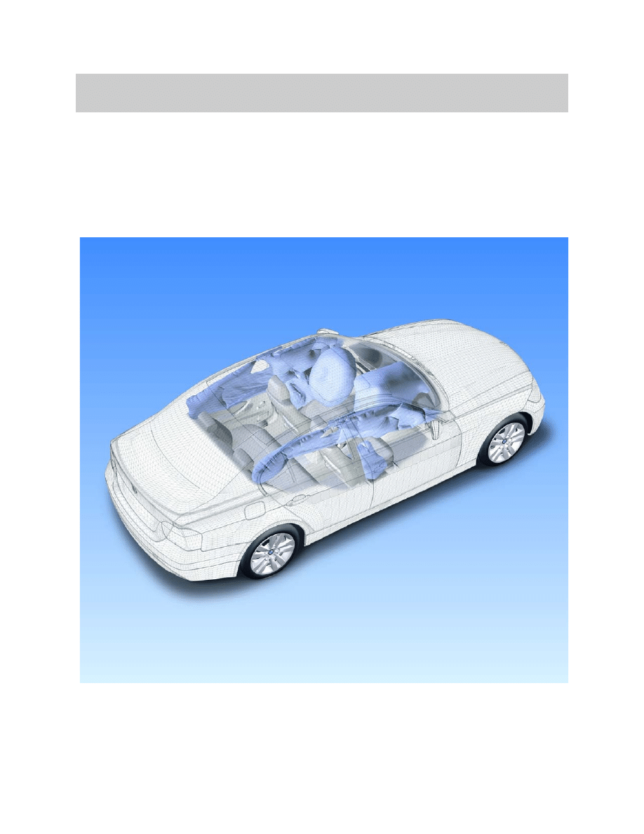
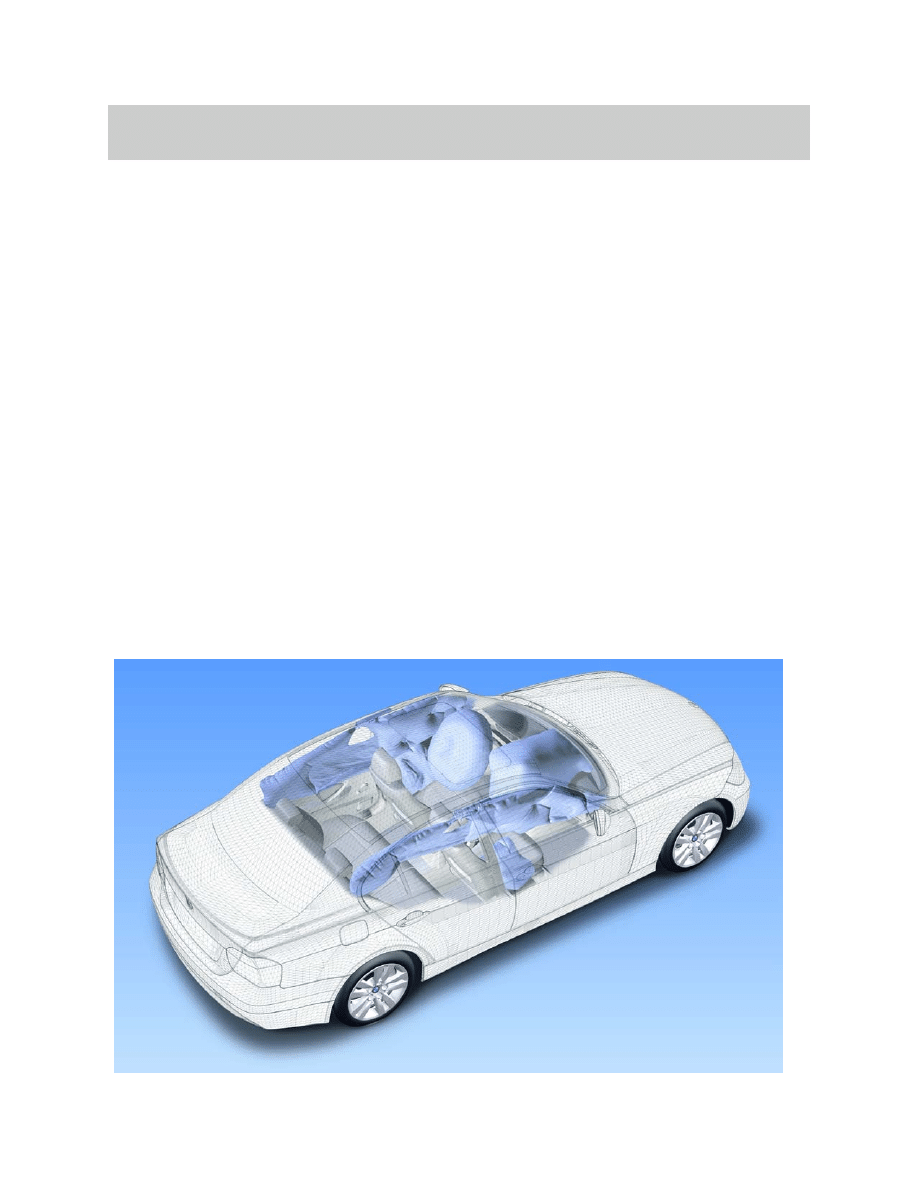
The Multiple Restraint System 5 (MRS 5) provides enhanced passive protection for
vehicle occupants in the event of a serious collision. The system is regarded as
passive in the respect that it operates automatically without interactions by the
vehicle occupants.
It differs from the previous MRS4 system in that reaction time is decreased and accuracy
increased due to the addition of the door pressure sensors and up front sensors.
3
E90 Multiple Restraint System 5
Purpose of System
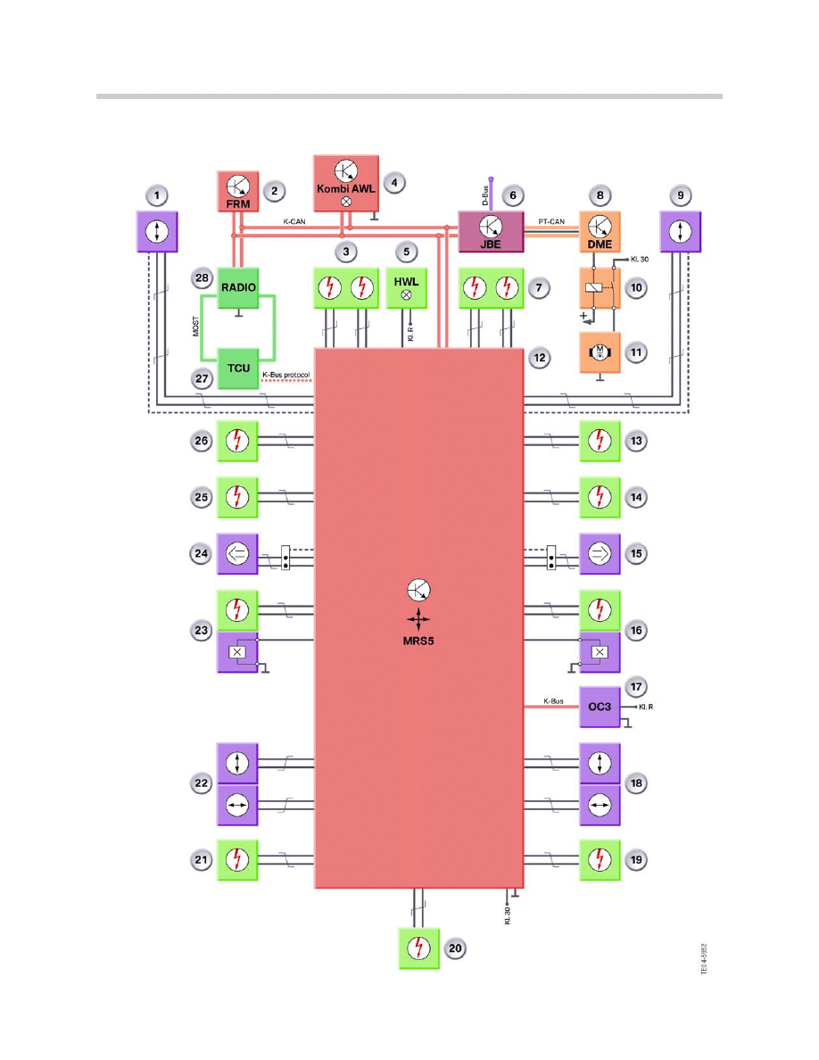
IPO
4
E90 Multiple Restraint System 5

Legend for IPO
5
E90 Multiple Restraint System 5
Index
Explanation
Index
Explanation
1
Up front sensor, left
15
Door pressure sensor, front right
2
Footwell module
16
Belt buckle status and
seat belt tensioner, front right
3
Driver’s airbag (dual stage)
17
OC-3 mat with built in analyzer
4
Instrument cluster
18
B-Pillar sensor, right
5
Airbag indicator lamp (AWL)
19
Seat belt tensioner, rear right
6
Junction Box Electronics Control Module (JBE)
20
Battery Safety Terminal
7
Front passenger’s airbag (dual stage)
21
Seat belt tensioner, rear left
8
Engine electronics control unit
22
B-Pillar sensor, left
9
Up front sensor, right
23
Belt buckle status and
seat belt tensioner, front left
10
Fuel pump relay (feeds EKP module)
24
Door pressure sensor, front left
11
Fuel pump
25
Driver’s thorax airbag
12
MRS5 control unit
26
Curtain airbag, left
13
Curtain airbag, right
27
Telematics control unit
14
Passenger’s thorax airbag, front
28
RAD2 or CCC
System Components
The MRS5 system consists the following components:
• MRS5 control unit
• Crash sensors - “b” pillar (x 2)
• Crash sensors - up front (x 2)
• Door pressure sensors (x 2)
• MRS warning lamp (in IKE)
• Slip ring
• Passenger seat occupancy detector (OC-3)
• Seat belt switches
• Driver’s airbag module
• Front passenger’s airbag module
• Driver’s side (thorax) airbag module
• Front passenger’s side (thorax) airbag module
• Curtain airbag - right side
• Curtain airbag - left side
• Driver’s seat belt pre-tensioner
• Front passenger’s seat belt pre-tensioner
• Battery Safety Terminal
6
E90 Multiple Restraint System 5
7
E90 Multiple Restraint System 5
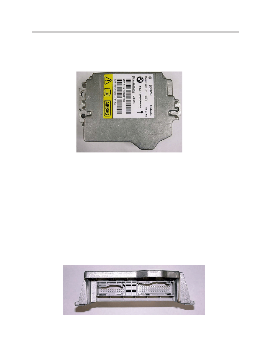
MRS 5 Control Unit
The MRS 5 control unit is secured centrally on the body floor panel (center tunnel -
between the handbrake and the gear selector lever) by two nuts. Access to the control
unit is only possible when the main floor carpet is removed from the vehicle.
The MRS 5 performs internal diagnosis and monitors all inputs and outputs. Any faults
that may occur are stored as non-volatile memory in the control unit and indicated to the
driver by way of the airbag warning lamp (AWL).
Communication with other control units in the vehicle system network takes place via the
K-CAN. In the event of a crash, a K-bus protocol is transmitted via a separate data line to
the telematics control unit (TCU) and the emergency call triggered.
The MRS 5 can be encoded via the K-CAN. Diagnosis of the MRS control unit takes
place via the diagnosis bus in the gateway module of the junction box which then for-
wards the diagnosis commands on the K-CAN.
Connector
The module has been expanded from one to two connectors.
• One 26-pin connector is for the cockpit
• One 54-pin connector if for the vehicle harness.
MRS Control Unit
MRS Control Unit
Crash Sensors
In addition to the two acceleration sensors in the MRS 5 control unit, satellites are
installed in the B-pillars, frame rails, and doors.
Together with the acceleration sensors in the MRS 5 control unit, the longitudinal,
transverse acceleration sensors and door pressure sensors serve the purpose of
detecting side crashes.
The longitudinal acceleration sensors detect front end and rear end crashes.
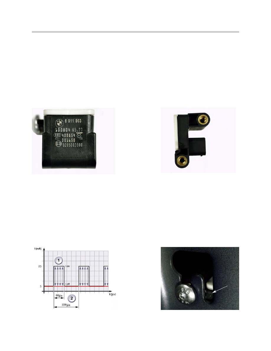
B-Pillar Satellite
The B-pillar satellite consists of a longitudinal acceleration sensor and a transverse
acceleration sensor. These B-pillar satellites serve the purpose of protecting frontal, side
and rear end crashes. The left and right sensors are of identical design and are allocated
by way of mechanical coding during installation. The sensors measure in both directions.
The acceleration values registered by the micromechanical acceleration sensors are con-
verted to digital signals. With the aid of a data telegram, the digital signals are transmitted
every 228 µs to the MRS 5 control unit. The transmitted data are evaluated in the MRS 5
control unit.
The main sensor direction provides a positive signal so that the control unit recognizes
the direction of impact.
8
E90 Multiple Restraint System 5
1. Data telegram with acceleration values
2. Data telegram spacing
1. Mechanical coding
1
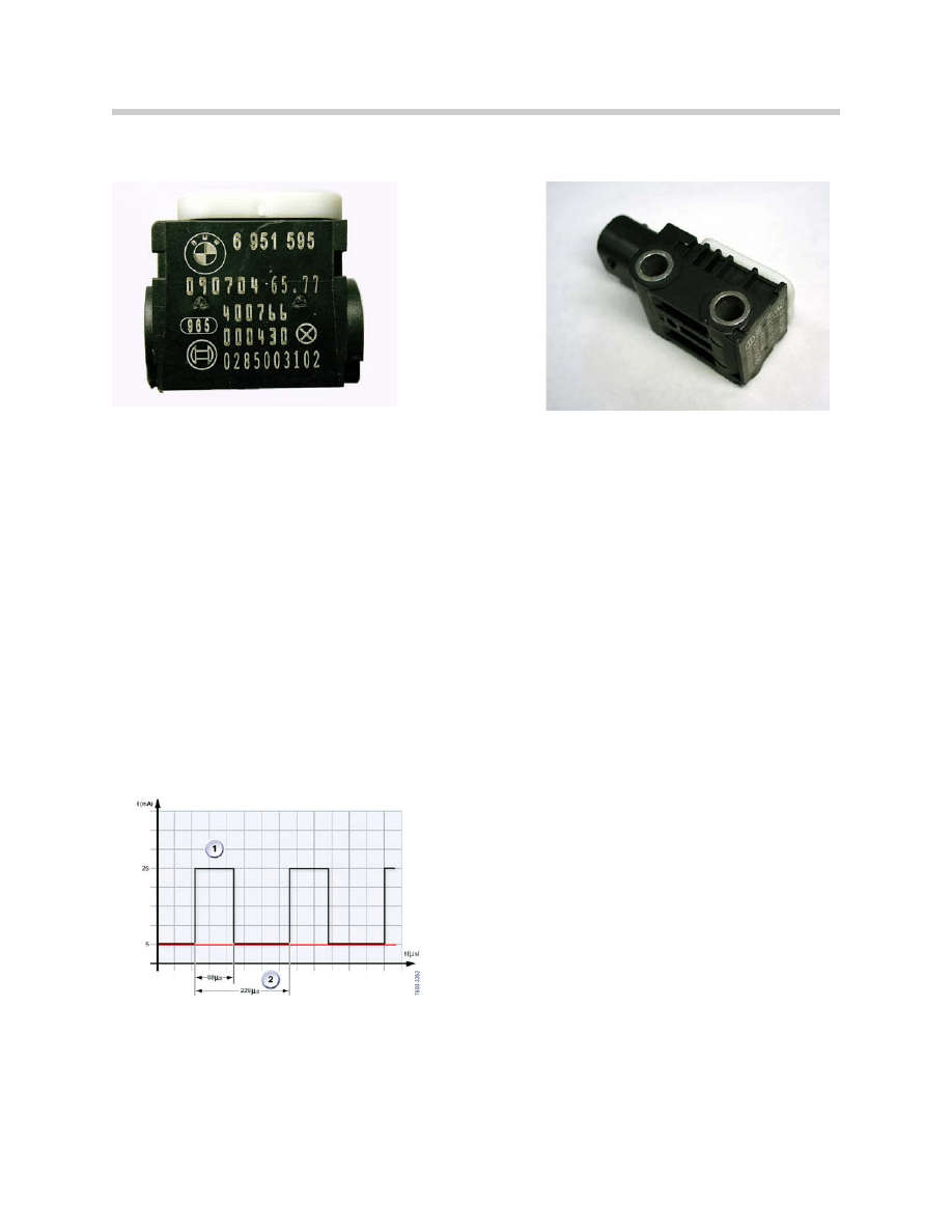
Up Front Sensor
The job of the up-front sensors is to detect frontal impacts. The up-front sensors are
located on the front frame rails. The up-front sensors provide the MRS control unit with
the initial information on the progression and severity of the impact.
An up-front sensor consists of an acceleration sensor for detecting deceleration, a signal
converter and a microprocessor for data transmission. The up-front sensors supply a
digital data message consisting of 11 bits (2 start bits, 8 data bits and 1 check bit) that is
transmitted cyclically every 228 µs.
The up-front sensors are supplied with power via a current-signal interface. The up-front
sensors are supplied with a current of 5 - 10 mA. When a data message is transmitted,
the level jumps vertically by 20 mA.
The advantage of the current-signal interface is its constant supply of current which pre-
vents corruption of the signal. A change of resistance in the lead does not affect the signal.
A power supply with a voltage signal would be corrupted by changes in resistance in the
lead. The signal could equally be corrupted by EMF interference from other leads.
9
E90 Multiple Restraint System 5
1. Data message length (11 bits)
2. Data message cycle
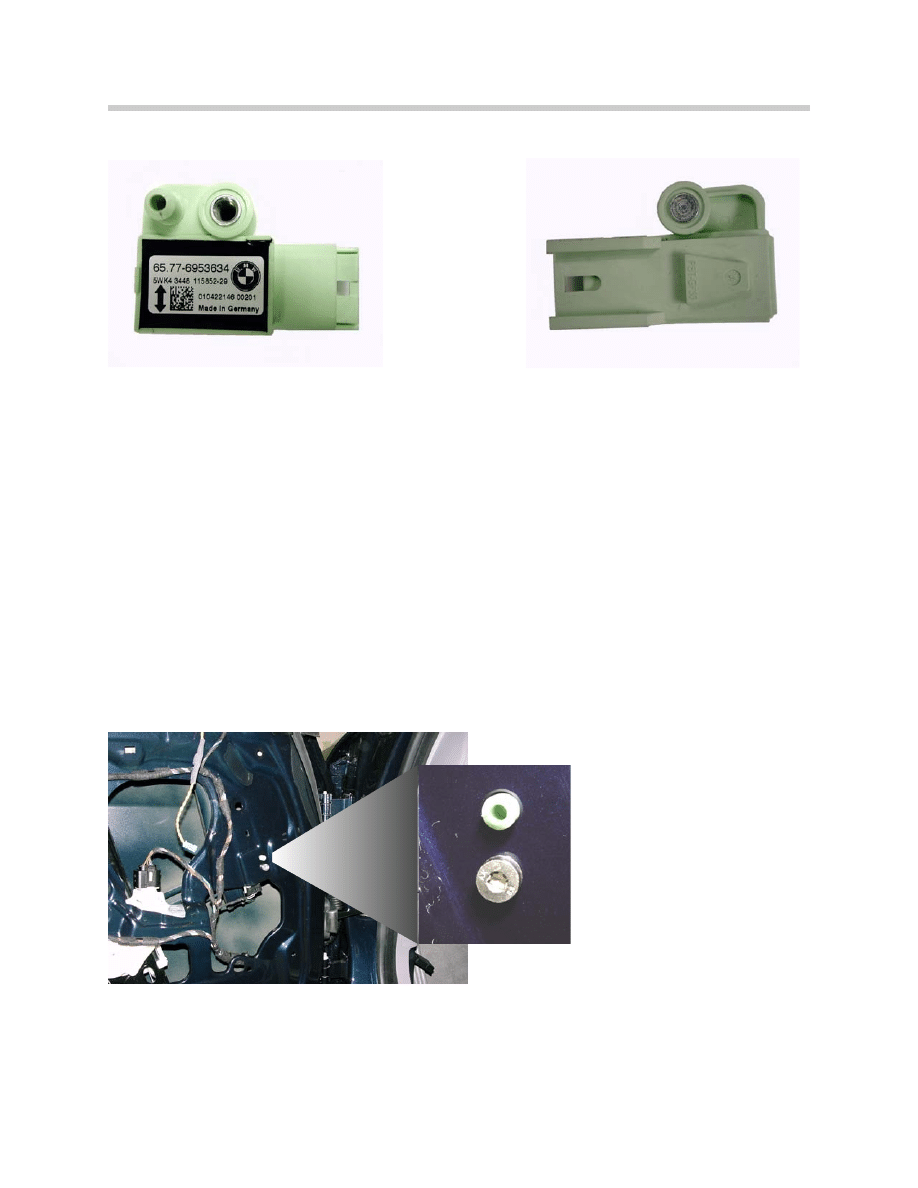
Door Pressure Sensor
The function of the door pressure sensors is to provide supplementary detection of side
impacts in addition to the information supplied by the lateral acceleration sensors in the
B-pillar satellites and the MRS5 control unit. The door-compression sensors are located
on the inner door panel and measure the pressure inside the door.
In the event of a side impact, the outer door panel may be pushed inward, thus
compressing the space inside the door and increasing the pressure. That pressure
increase is detected by the door pressure sensors.
A door compression sensor contains not only a pressure sensor but also an electronic
module. The pressure readings are digitized and transmitted cyclically as a data message
to the MRS5 control unit.
At the same time, the side impact is detected by the acceleration sensors in the B-pillar
satellite. The B-pillar satellite then also transmits a data message. The MRS5 control unit
in the center of the vehicle processes the two signals and is able to trigger the restraint
systems on the basis of the information provided.
10
E90 Multiple Restraint System 5
Door Pressure Sensor Mounting
11
E90 Multiple Restraint System 5
Airbag Warning Lamp (in IKE)
The red MRS warning LED is located in the instrument cluster and is illuminated for a
short period after switching the ignition to position 1.
If a fault is present within the MRS, the LED will illuminate and remain on until the ignition
is switched off. A check control icon will also appear in either yellow or red depending on
the system fault along with a brief text message. With the warning LED illuminated, the
MRS may not operate in the event of a collision.
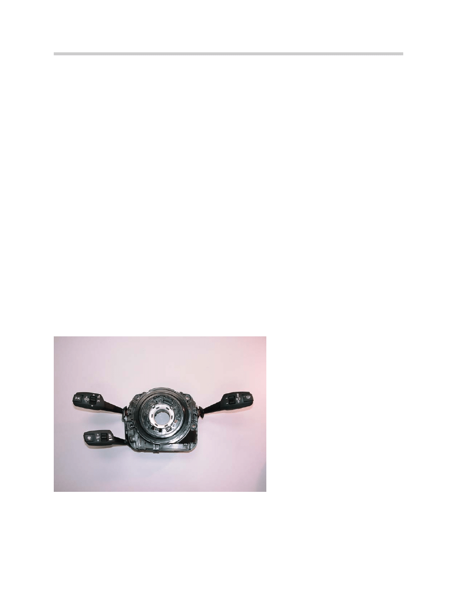
Slip Ring (Rotary Coupler)
The slip ring is installed on the steering column, behind the steering wheel to provide
the electrical interface between the fixed wiring harness and the moveable driver airbag
module. The rotary coupler is attached to the steering column casting by three screws.
In addition to the wiring for the driver airbag, the slip ring also provides the wiring for other
electrical functions built into the steering wheel area, these may include:
• Audio system remote control switches
• Cruise control system switches
• Horn switches
A rotating link harness is enclosed in a plastic cassette comprising outer and inner hous-
ings with integral connectors. The cassette contains a flat ribbon type flexible cable. The
slip ring housing is part of the direction indicator and windshield wiper/washer housing.
The complete assembly is attached to the steering column by three screws.
Slip Ring
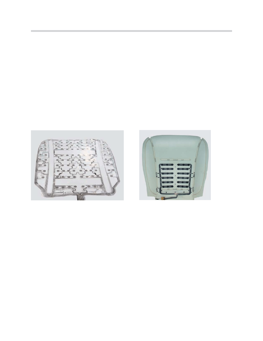
Seat Occupancy Detector (OC-3 Mat)
The purpose of the OC-3 mat is to monitor the presence of a person or object placed on
the front passenger’s seat and determine whether the passenger airbags should be
deactivated. The OC-3 mat is capable of detecting a child seat that conforms to the rele-
vant standard (NHTSA FMVSS 208) by virtue of the pattern of the impression it makes
on the seat and deactivates the passenger airbags.
The previous SBE mat recognized a certain weight as proof that the seat is occupied. In
order to meet legislative requirements, the seat occupancy detector (SBE) has been
developed into an intelligent occupant classifier (OC). This was achieved by means of the
following measures:
• By a larger number of sensor elements
• By sensing a larger area of the seat
• By an intelligent electronic analyzer
The OC-3 mat is capable of distinguishing between a one-year-old child in a child's seat
and a light person.
The OC-3 mat is integrated into the seat area of the passenger seat. The OC-3 mat
consists of conductors with pressure-dependent resistor elements (FSR, or Force
Sensitive Resistance Elements). The conductors are connected to the electronic analyzer.
The FSR elements are wired in such a way that they can be sampled individually. When
the mechanical load on a sensor element increases electrical resistance decreases and
the measurement current changes accordingly.
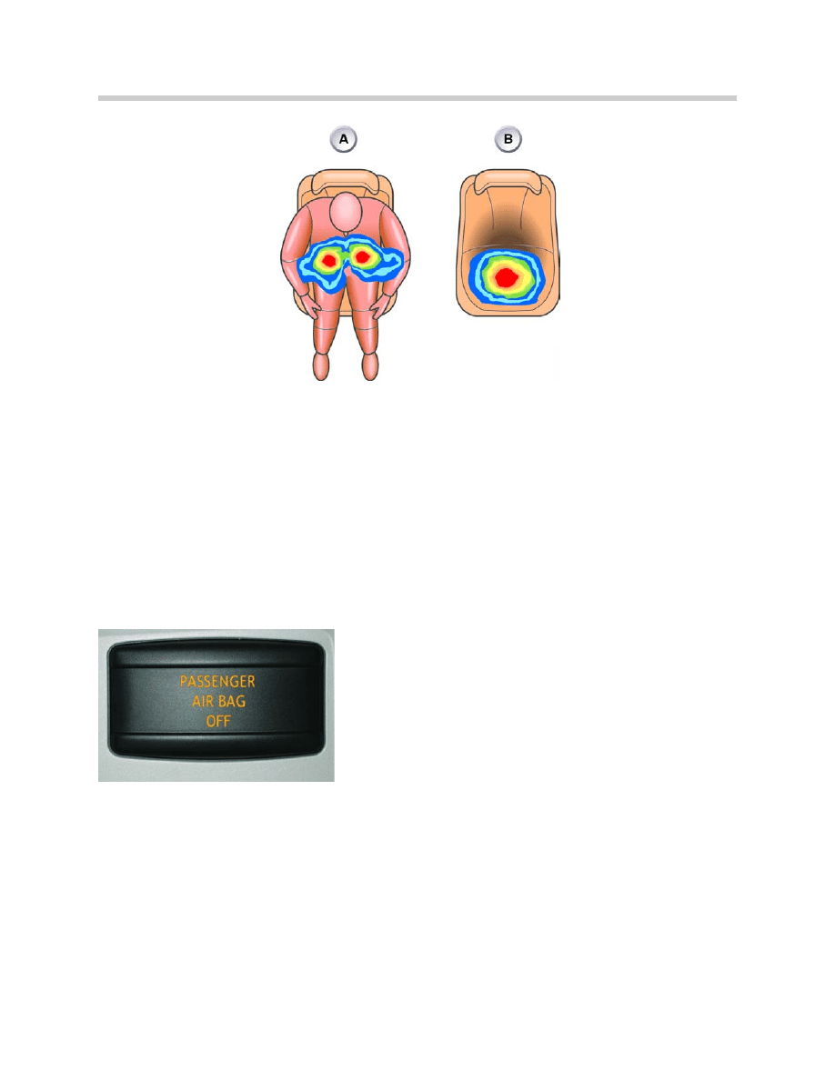
By analyzing the signals from the individual sensors, the analyzer maps the occupancy of
the seat surface and can identify the local concentrations of weight. The distances
between the areas where pressure is applied and the concentrations of pressure reveal
whether the seat is occupied by a person (A) or a child seat (B) (diagram on next page).
12
E90 Multiple Restraint System 5
OC3 Mat
Convention Seat Occupancy Detector
The analyzer of the OC-3 mat sends a message to the MRS5 control unit via the K-CAN.
If the system detects that the seat is unoccupied or that a child seat for a child up to one
year old is fitted, the airbags on the passenger side are deactivated. The MRS5 control
unit switches on the airbag warning light. The airbag warning light indicates that the
airbags on the passenger side are deactivated.
Airbag Warning Light (status LED)
The airbag indicator lamp is located in the roof vehicle center (coupe) or on the wind-
shield frame next to the convertible top and rear window switches (convertible). The
airbag indicator lamp is activated and lights yellow when the front passenger airbag and
the side passenger airbag are deactivated.
Belt Buckle Switch
The belt buckle switch is used to detect whether the seatbelt has been fastened or not.
The detection signal is sent to the MRS5 control unit. The signal is used as a criterion for
selective triggering of the actuators in the event of a crash. The belt buckle switches are
located in the seatbelt buckles of both front seats.
The belt buckle switch is a two-wire Hall switch. The Hall switch is supplied by the MRS5
control unit via a current-signal interface. The current draw of the switch is the signal for
the switch position. The belt buckle switch is permanently diagnosed and monitored in all
electrical system statuses from Terminal R "ON" onwards.
13
E90 Multiple Restraint System 5
Pyrotechnic Devices
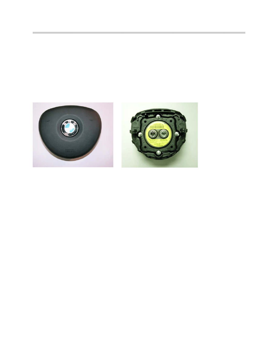
Driver’s Airbag Module
The driver’s airbag is of a two-stage design and attached to the steering wheel by two
captive bolts. Electrical connection to the MRS control unit is provided via the rotary
coupler. Once the airbag is fully inflated, vents in the airbag prevent further pressure
build-up, so that progressive deceleration is provided as the driver contacts the cushion
and injury due to sudden impact forces is prevented.
Note: To remove the airbag connector, remember to first release the built on
lock. If the connector is not removed correctly, damage may result.
Passenger Airbag Module
The passenger front airbag module is of a two-stage design and is located above the
glove box, directly in front of the passenger seat. The airbag module is mounted to the
body cross car beam.The unit contains a gas generator and igniter module.
Upon deployment, airbag tears the dashboard cover through several predetermined sheer
points (dashboard cover would have to be replaced). Once free of the housing and fascia
the airbag inflates to its full extent to provide a protective cushion between the front seat
passenger and the fascia/windshield.
Vents in the airbag prevent excess pressure bursting the bag and, as soon as the material
in the gas generator is exhausted, the airbag deflates.
Note: Only use the service connector when removing the passenger airbag.
The connector at the airbag itself should not be tampered with.
14
E90 Multiple Restraint System 5
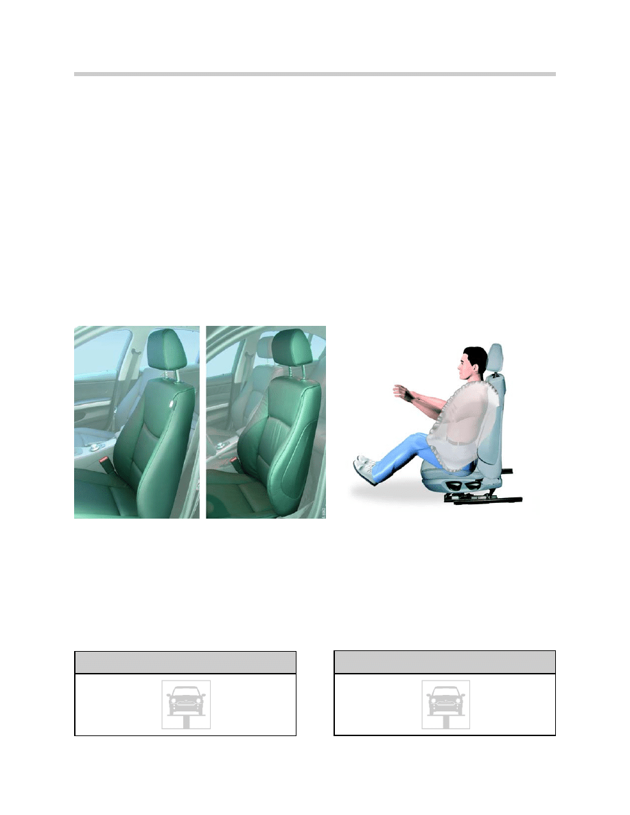
Side (Thorax) Airbag Modules
The driver and passenger side (thorax) airbags are mounted to the front seat backrest
frame and are designed to protect the front driver and front passenger during a side
impact.
The modules are side specific (i.e. a right hand module must be fitted to a right hand seat
and a left hand module must be fitted to a left hand seat). The side airbags are activated
by a control signal from the MRS control unit in the event of a side impact or a front
angled impact of sufficient severity to cause both front and side airbag deployment.
The side (thorax) airbag module is consists of a molded plastic case which houses a
folded nylon fabric bag, the gas generating capsules and an igniter squib. The rear of the
side airbag module features two studs that are used for mounting the module to the seat
frame and are secured in position by two nylon lock nuts.
The side airbag modules have a 2-pin connector under the seat where it connects to the
main harness.
15
E90 Multiple Restraint System 5
Side Airbag Module
Do not try to remove the connector at the mod-
ule end, it is a permanent connection.
Workshop Hint
If a new side airbag module shows any sign of
damage,
DO NOT USE.
Workshop Hint
16
E90 Multiple Restraint System 5
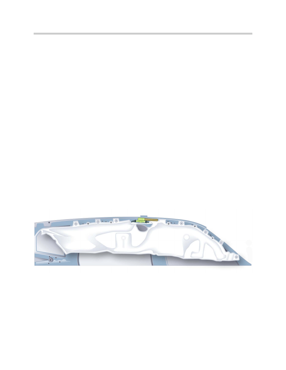
Curtain Airbag
The E90 is equipped with the same type of head protection system as the E83 (X3)
installed as standard equipment.
The curtain airbag extends all the way from the A-pillar to the C-pillar, covering the entire
side-window area. The curtain airbag inflates between the vehicle occupants and the side
windows and pillar trims.
The curtain airbag reduces the risk of occupants' heads or other extremities protruding
through the windows in a sideways collision. This leads to less severe neck backlash
forces and less severe head injuries.
Advantages of the system:
• Extended covered area for side windows front and rear.
• Protection against glass splinters and penetrating objects.
• Optimized protective area offering protection for occupants of differing sizes.
The curtain airbag is positioned along the line of roof side member, folded up. It consists
of a gas generator, the two gas nozzles and the curtain.
In the event of a “severe enough” side collision, the generator is detonated and the gas
flows through the two gas nozzles into the curtain. Simultaneous inflation of the curtain at
the front and back achieves more even deployment.
Because the curtain generators and curtain are a sealed system, the curtain airbag retains
its shape and strength for several seconds.
Side Curtain Airbag
17
E90 Multiple Restraint System 5
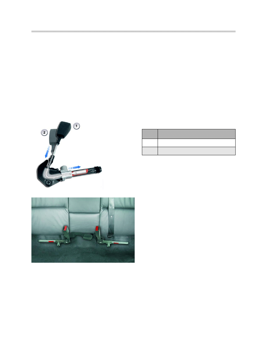
Seat Belt Pre-Tensioners
Inertia reel three point seat belts are installed on the front and rear seats. The inertia reels
are of the ALR (Automatic Locking Retractor) type. The MRS control unit deploys the
pyrotechnic seat belt pre-tensioners at a slightly lower threshold level than the front
airbags.
The two pre-tensioners are side specific, but otherwise identical. Each pre-tensioner has
a tube containing propellant and a piston. The piston is attached to a steel cable, the
opposite end of which is attached to the seat belt buckle. An igniter (squib) in the base of
the tube provides an ignition source when triggered by a fire signal from the MRS control
unit.
A “pigtail lead” with a 2-pin connector links the igniter to the vehicle’s MRS wiring and is
located on a bracket underneath the seat frame.
Index
Explanation
1
Seat Belt Buckle (fully extended)
2
Seat Belt Buckle (fully retracted)
Rear Seat Belt Tensioners
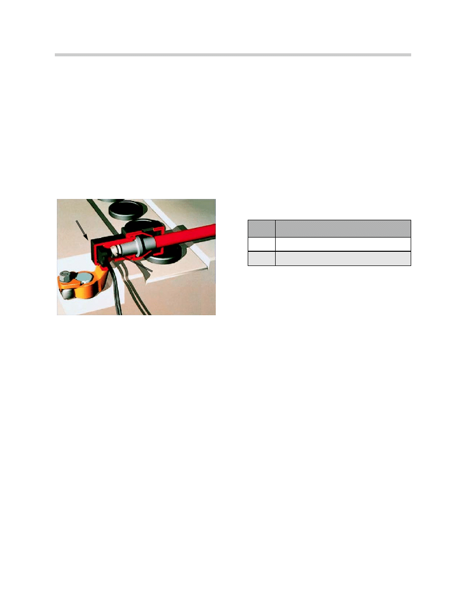
Battery Safety Terminal
The BST is installed due the battery location in the luggage compartment. The BST is
used to minimize the possibility of a short circuit to the heavy gauge B+ wire that runs the
length of the vehicle in the event of an accident.
The BST consists of a conventional clamp that is screwed onto the positive terminal from
above and connected with a hollow cylinder. A propellant charge is stored in this hollow
cylinder. Just as with the airbag and seat belt pre-tensioner, this pyrotechnic device is
controlled and ignited by the MRS5 control module. The triggering strategy is also the
same as for the triggering of the airbag, and it possesses identical protection logic. The
overall unit is enclosed in a plastic shell that captures the cable if it is forced out and locks
it so that a renewed contact is no longer possible.
18
E90 Multiple Restraint System 5
Index
Explanation
1
2-pin Connector from MRS5 Control Unit
2
Propellant Charge
1
2

19
E90 Multiple Restraint System 5
MRS 5 Control Unit
The MRS5 control unit performs the following functions:
• Crash detection and determining triggering point
• Triggering the ignition output stages
• Documentation of crash data
• System self-test
• Cyclic monitoring
• Display of system standby status
• Fault indication and fault code storage
• Fault output (diagnosis)
• Output of a crash telegram for other users in the communication system network
• Activation of the airbag indicator lamp when the passenger airbag is deactivated
Crash Detection and Determining Triggering (ignition) Point
The MRS 5 control unit determines whether a crash situation has occurred based on the
values detected by the sensors and the triggering algorithm. The threshold values of two
independent sensors must be detected in order to detect a crash. In the case of a frontal
crash for example, the acceleration values from the B-pillar satellite and from the
longitudinal acceleration sensor must be detected in the control unit.
The values serve the purpose of determining the crash severity and the crash direction.
Based on the crash severity and direction, an algorithm determines the triggering
(ignition) points of the restraint systems to be activated.
Triggering the Output Stages of the Ignition Circuits
The values from two different sensors, from the B-pillar satellite and MRS control unit
sensor must be applied in order to trigger the output stages of the ignition circuits.
Voltage is supplied to the MRS 5 control unit as from terminal R "ON" and the unit is
operational once it completes a system self test.
The ignition capacitor that serves as an energy reserve is charged by means of a
chopper-type regulator. The ignition capacitor provides the energy reserve in the event of
a crash with the power supply interrupted.
The output stages of the ignition circuit consists of a high side and a low side power
switch. The high side power switch switches the triggering (ignition) voltage, the low side
power switch switches ground (earth). The output stages of the ignition circuits are con-
trolled by the microprocessor.
The high side and low side power switches also serve the purpose of checking the igni-
tion circuits during the system self-test.
Principles of Operation

Documentation of Actuator Triggering in Terms of Time
The triggering (ignition) commands must be recorded in the event of a crash where one
or several actuators are triggered. The most important data of a crash event are stored in
the form of a crash telegram in the non-volatile memory of the control unit. Only the
development departments can read the crash telegrams.
A maximum of 3 crash telegrams can be stored. The control unit must then be replaced.
System Self-test
The MRS 5 performs a system self-test as from terminal R "ON". The airbag warning
lamp is actuated for 3 - 5 s during the system self-test.
When the system self-test is concluded and no fault has been found, the airbag warning
lamp goes out and the system is ready for operation.
Cyclic Monitoring
Once the system self-test has been successfully concluded and the system is ready for
operation, a cyclic monitoring procedure is performed for fault monitoring purposes.
Cyclic monitoring is carried out for as long as the system is at terminal R "ON".
Indication of System Operability
The system operability of the MRS 5 is indicated by the airbag warning lamp AWL going
out in the instrument cluster.
Fault Indication and Fault Code Storage
A fault in the system is indicated by the airbag warning lamp.
If a fault occurs in the MRS 5 system, the corresponding fault code is stored in a non-
volatile fault code memory. A distinction is made between internal and external faults
when entering the fault code.
Fault Output (diagnosis)
With the aid of the diagnostic tools (DIS plus, GT1), the fault code memory can be read
out via the diagnosis interface.
After rectifying the faults, the fault code memory can be cleared by means of the "clear
fault code memory" diagnosis command.
20
E90 Multiple Restraint System 5

Output of Crash Telegram
In the event of a crash involving triggering of the restraint systems, the MRS 5 control unit
sends a crash telegram to the users in the bus system network.
As a result, the respective control units perform the following functions corresponding to
the crash severity:
Deactivation of Passenger Airbags
The front and side passenger airbags must be deactivated when a child seat is mounted
on the passenger's side. This MRS utilizes an OC-3 mat for passenger seat occupancy
recognition.
Airbag deactivation is indicated by the yellow symbol lighting in the airbag indicator lamp.
Deactivation and activation of the passenger airbag is the responsibility of the vehicle driver.
Seat Belt Reminder Function
A seat belt reminder function is installed on this MRS version for the driver and passen-
ger. The Seat Belt Reminder SBR function monitors whether the driver or passenger has
fastened his/her seat belt. It not, a corresponding indicator reminds them to fasten their
seat belt. Both seat belt buckle switches are monitored separately.
If the seat belt is not worn or the seat belt is unbuckled while driving at a speed in excess
of approx. 1 km/h, there will be an audible and visual warning given.
The seat belt warning is given by:
• Fixed seat belt indicator lamp (seat belt symbol)
• Audible warning provided by the gong
21
E90 Multiple Restraint System 5
Control Unit
Function
Fuel Pump (EKP) Control Module
Switch off fuel pump
DME Control Module
Switch Off Generator
Junction Box (JB)
Release central locking
Footwell Module (FRM)
Activate hazard lights
Footwell Module (FRM)
Activate interior lights
Telematics Control Unit (if equipped)
Activate Emergency CAll

The SBR function is subdivided into two phases. The first phase is the initialization, i.e.
fastening the seat belt before driving off and during the first 200 m covered. The second
phase involves monitoring while driving, i.e. the system monitors whether the occupants
have their seat belts fastened during vehicle operation.
Phase 1 Initialization
Phase 1 begins with terminal 15 ON and remains active until the respective seat belt
contact is closed or terminal 15 OFF is detected.
At terminal 15 ON, the fixed indicator lamp for seat belt warning in the instrument cluster
is activated until the seat belt is fastened. The seat belt warning lamp requests the driver
to buckle his/her seat belt.
No warning is given over the first 200 m if the seat belt buckle is detected as open
(unbuckled). This provides the driver with the opportunity to drive out of the garage for
example and to close the door or to reposition the vehicle without the audible or visual
warning signal triggering.
An audible and visual warning signal is given after a distance of 200 m has been
exceeded and the system detects that the driver's seat belt buckle has not been
fastened or the front passenger's seat belt buckle has not been fastened and the seat
is detected as occupied.
The gong is additionally activated intermittently for maximum 90 sec or until the seat belt
is fastened . At the same time, the variable indicator lamp with the seat belt warning sym-
bol is activated. On vehicles with the central information display, a text message "Fasten
seat belt" is displayed for maximum 23 sec.
Phase 2 Monitoring During Vehicle Operation
For the driver, the transition to phase 2 takes place when the seat belt buckle switch
detects a fastened seat belt after approx. 15 sec or when covering the specified distance
(>200 m). If the front passenger seat is detected as occupied, the front passenger switch
must also detect that the passenger seat belt is fastened so as not to trigger a warning.
A visual and audible warning is triggered 15 sec after unbuckling the seat belt while driv-
ing. The gong is activated intermittently for maximum 90 sec or until the seat belt is fas-
tened again. At the same time, the seat belt warning symbol is activated.
If a warning was given for more than 90 sec, the SBR function is not activated again until
the seat belt has been fastened and unbuckled again.
22
E90 Multiple Restraint System 5
Document Outline
- Main Menu
- E90 Complete Vehicle
- E90 Suspension & Chassis Components
- E90 Voltage Supply and Bus Systems
- E90 Powertrain
- E90 Dynamic Driving Systems
- E90 General Vehicle Electrical
- E90 General Vehicle Electrical II
- E90 Driver Information Systems
- E90 Entertainment and Communication
- E90 Climate Control
- E90 Multiple Restraint System 5
- E61 Sport Wagon
- E65/66 Model Update
- Glossary
Wyszukiwarka
Podobne podstrony:
więcej podobnych podstron