P O P U L A R M E C H A N I C S
64
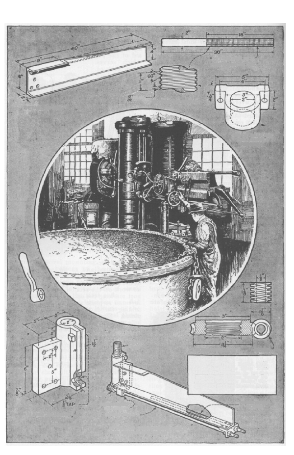
ARM BEARING
CAST IRON
DETAIL OF TRAVERSING SCREW
AND ELEVATING GEAR
WORM SHAFT
WORM-SHAFT
BEARING
WORM
TRAVERSING
SCREW
What the Giant Radial Drill
Is to the Large Shop This
Little Drill Press Is to the
Small One; It Can Easily Be
Adapted to Power Drive, Us-
ing an Ordinary Electric Drill
PIVOT
BAR
WORM-WHEEL NUT
WORM
PIVOT BEARING,
CAST IRON, 2
REQUIRED
SECTION OF THREAD
DETAIL OF ARM
FLAT
PIVOT-BAR DETAIL
4 THDS PER INCH
A Radial Drill Press for Small Shop
By J. V. ROMIG
OST mechanics, while appreciating
t h e value of the radial drill press in
the large shop, and realizing what a help
such a tool on a smaller scale would be in
the small experimental shop, look upon its
construction as beyond the scope and ca-
pacity of the small shop. Such is not the
case, however, as a glance at the accom-
panying drawings will prove. In this de-
sign, the machine work necessary has
been reduced to the m i n i m u m , and all of
it is w i t h i n the capacity of a shop equipped
with a good lathe. A drill press of this
type is capable of a much wider range of
work than the ordinary post drills and
bench drill presses found in the small
shop. As it can be swung back against
the wall when not in use, it can be used
where bench room is limited; it will drill
holes anywhere within a 38-in. radius
from the pivot bar, and thus is of special
advantage on sheet-metal work, on heavy
jobs that cannot be handled easily on ac-
count of their weight, and where holes
must be drilled in the center of pieces of
large diameter.
The arm is made of 6-in. channel iron.,
cut to the length shown in the drawing,
and with one flange cut away for a p o r -
tion of its length. To the rear end is
bolted a casting that forms the pivot bear-
ing: the dimensions of this bearing are
given in a detail, and it is split and fitted
with capscrews and a clamping lever. The
slide for the drill head is made of a 36-in.
M
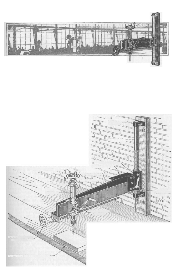
Perspective View of the Finished Radial Drill, Show-
ing the General Assembly of the Parts
length of ½ by 4-in. cold-rolled steel; this
is fastened to the arm by means of ¼-in.
flat-head machine screws, which go all the
way through and are fitted with nuts on
the inside face of the channel. Between
the slide and the arm is a filler strip of .375
by 3¼-in. cold-rolled steel 32 in. long,
machined to 3.125 in. in width. Both of
65
CAST-IRON BENCH BLOCK
INTERCHANGEABLE.
HANDWHEEL
TRAVERSING
SCREW
SPINDLE.
NUT
VERTICAL FEED
GUIDE RODS
STEEL SLIDE
WORM
ELEVATING
NUT
CHANNEL IRON
ARM BEARING
PIVOT BAR
PIVOT
BEARING
P O P U L A R M E C H A N I C S
66
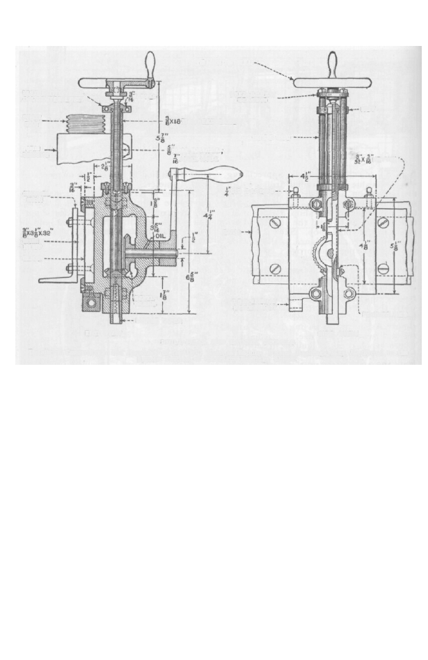
4 HANDWHEEL
FEED-SCREW
BEARING
NUT
GUIDE ROD
THD. FEED SCREW
TAPPED
FEED NUT, DIVIDED
ON CENTER LINE
PIVOT
BAR
ARM
BEARING
DIAM. SPINDLE.
AXIAL HOLE
GIB SCREWS
KEYWAY
CHANNEL
IRON
SHIM
STRIP
SLIDE
SHIM
TRAVERSING
SCREW NUT
SIDE VIEW
FEATHER KEY
MORSE TAPER
BEVEL
GEARS
END VIEW
Details of Construction and Assembly of the Drill Head or Saddle; Bronze Bushings May Be Fitted to the
Spindle Instead of the Plain Bearings Shown
DRILL-HEAD AND SADDLE DETAILS
these cold-rolled pieces must be very care-
f u l l y straightened and the edges scraped
true. It is also necessary to take care that
the slide and the pivot bearing are square
with each other.
The pivot bar is made of 2-in. cold-
rolled steel, threaded for 18 in. of its
length. The thread is of sharp V-form
at the bottom, but flattened on top, as
shown in the detail; this provides a sur-
face for the bearing, while not interfering
with the function of the screw. The
worm wheel is used to elevate the arm to
the desired height; it is made of bronze
to the dimensions given, and is actuated
by a steel worm on a shaft extending to a
bearing on the front of the arm. The
pivot bar is held against the wall by pin-
ning it in bearings at each end, which, in
turn, are bolted to a stout stringer fas-
tened to the wall by lagscrews or expan-
sion bolts. A plumb bob is used to set the
bar exactly vertical on the wall. When in
use, the arm may be held fast in any posi-
tion on the pivot bar by means of the
clamp screws.
The drill head, or saddle, is a casting,
machined to fit on the slide and drilled
and bored for the drill and hand-crank
spindles. The bearings are split; the
front half of the casting also has the bear-
ing for the crank spindle. A suitable pair
of bevel gears, of 1 to1½ ratio, are pur-
chased, and the larger gear is pinned to
the crank spindle, as also is the crank
handle; the spindle is ½ in. in diameter,
and the bearing is drilled for an oil hole
as in the drawing. The small gear is fit-
ted with a feather key, and, when in place
on the spindle, rides on a fiber washer.
The spindle is turned from good machin-
ery steel, and is bored at the lower end to
No. 1 Morse taper. A groove is turned
in the upper end to take the feed nut, and
a .437-in. hole bored axially to clear the
feed screw. The groove is highly finished.
The feed is effected by means of a split
nut of novel design, which is a nice run-
ning fit in the groove in the spindle and is
threaded internally to fit the feed screw.
It is prevented from t u r n i n g by two guide
posts, one on either side, the posts also
supporting the top bearing of the feed
mechanism. The nut must slide freely on
the posts, and is provided with an oil hole.
The posts are screwed into a steel collar
which is fastened to the top of the upper
spindle bearing; a similar collar forms the

P O P U L A R M E C H A N I C S
upper feed-screw bearing, and to the top
of the screw is pinned a small handwheel.
The spindle bearings can be fitted with
bronze bushings if desired; and this is,
in fact, preferable, as it will add to the life
of the machine.
The top of the upper saddle slide, bear-
ing on the rail, is tapped for two ¼-in. set-
screws, which are used to adjust the gib to
the slide. The gib is made of sheet brass,
bent up at each end to prevent it from
coming out, and both the upper slide and
the gib should be drilled for oil holes. A
brass or bronze nut for the traversing
screw is screwed to the lower surface of
the saddle, and a bearing for the screw
and the worm shaft is fastened to the
front of the arm. The ends of both the
screw and shaft are squared to fit an in-
terchangeable handwheel.
A good table or faceplate can be made
from an iron bench plate, and care should
be taken to see that the press and the top
of the plate are square with each other in
every direction. The best location for the
drill is near the end of the bench, so that
the drill can be swung over the end of the
latter for work that cannot be raised to
the bench. A d r i l l chuck of ½-in. capacity
is fitted to the s p i n d l e ; although the gears
are strong enough to drive drills larger
t h a n ½ in., it is s e l d o m , in the small shop,
that larger d r i l l s will be used in the ma-
chine. Larger holes, however, may be
bored with a boring bar held in the chuck.
The head may be modified with very
little trouble to make the tool power-
driven, by using an electric drill and
mounting it on a saddle designed on the
same lines as the one shown, but modi-
fied to suit the drill. If t h i s is done, the
tool would be an ideal one for the garage
or woodworking shop as well as the small
machine shop.
Wyszukiwarka
Podobne podstrony:
więcej podobnych podstron