Edition 11.01
BJA24807010001
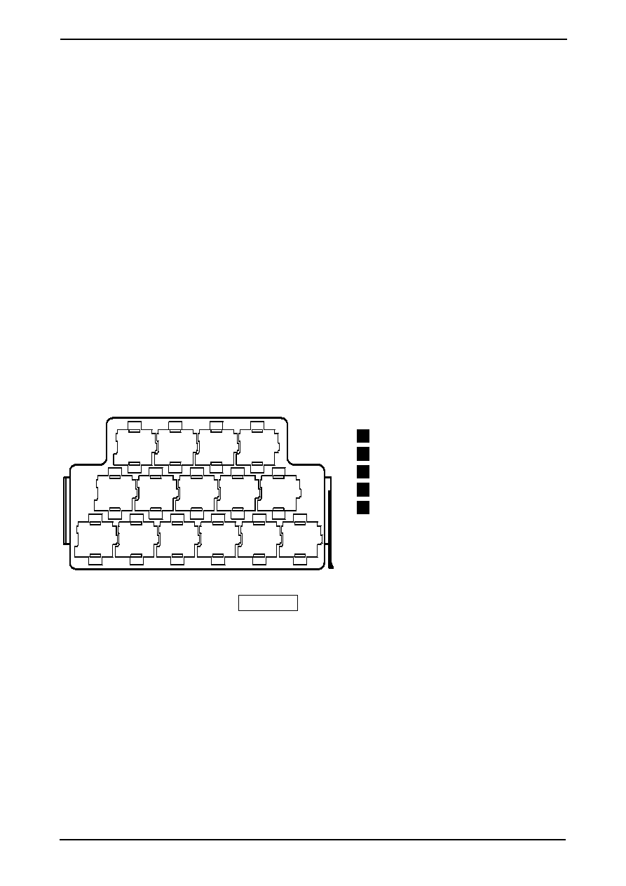
Different relays, fuses and multiple connectors fitted: see section ”Positioning”.
Fuse colours
30 A -- green
25 A -- white
20 A -- yellow
15 A -- blue
10 A -- red
7.5 A -- brown
5 A -- beige
3 A -- purple
Note:
In the brackets behind the component designation are
the production control numbers on the casing
Relays fitted to the 15 relay plate
Current flow diagrams
Glow plug relay (103)
3
1
2
3
4
5
6
7
8
9
10
11
12
13
14
15
E97--0084
Diesel direct injection system relay (109)
10
Fuel pump relay (167)
13
High heat output relay (100)
14
Low heat output relay (53)
15
Ibiza
No. 4/1
1.9 l -- TDI/74 kW, engine code letters ATD
1.9 l -- TDI/96 kW, engine code letters ASZ
from November 2001
1
2
3
4
5
6
7
8
9
10
11
12
13
14
97-42650
B
30
50
C
D+
C1
B+
G
M
6d/3
T
D
/50
W
27
T18/9
2j/1
T
bl
0.5
li/gn
0.35
2j/2
T
11a/1
T
ro/sw
2.5
ro/sw
2.5
bl
0.5
bl
0.5
br/ro
0.5
sw
25
XS4
15
ro
4
sw
35
--
+
A
ro
35
T18/8
12a/7
T
br
0.5
XS4
br
0.5
sw
25
1
98
sw
16
3/3
T
sw
16
162
S
175A
176
S
50A
P1
1
4
163
S
110A
2
*
sw
25
2
Edition 11.01
BJA24807010001
Current flow diagrams
ws = white
sw = black
ro = red
br = brown
gn = green
bl = blue
gr = grey
li
= purple
ge = yellow
or = orange
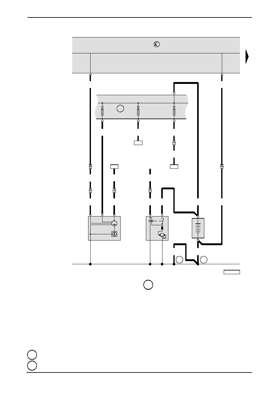
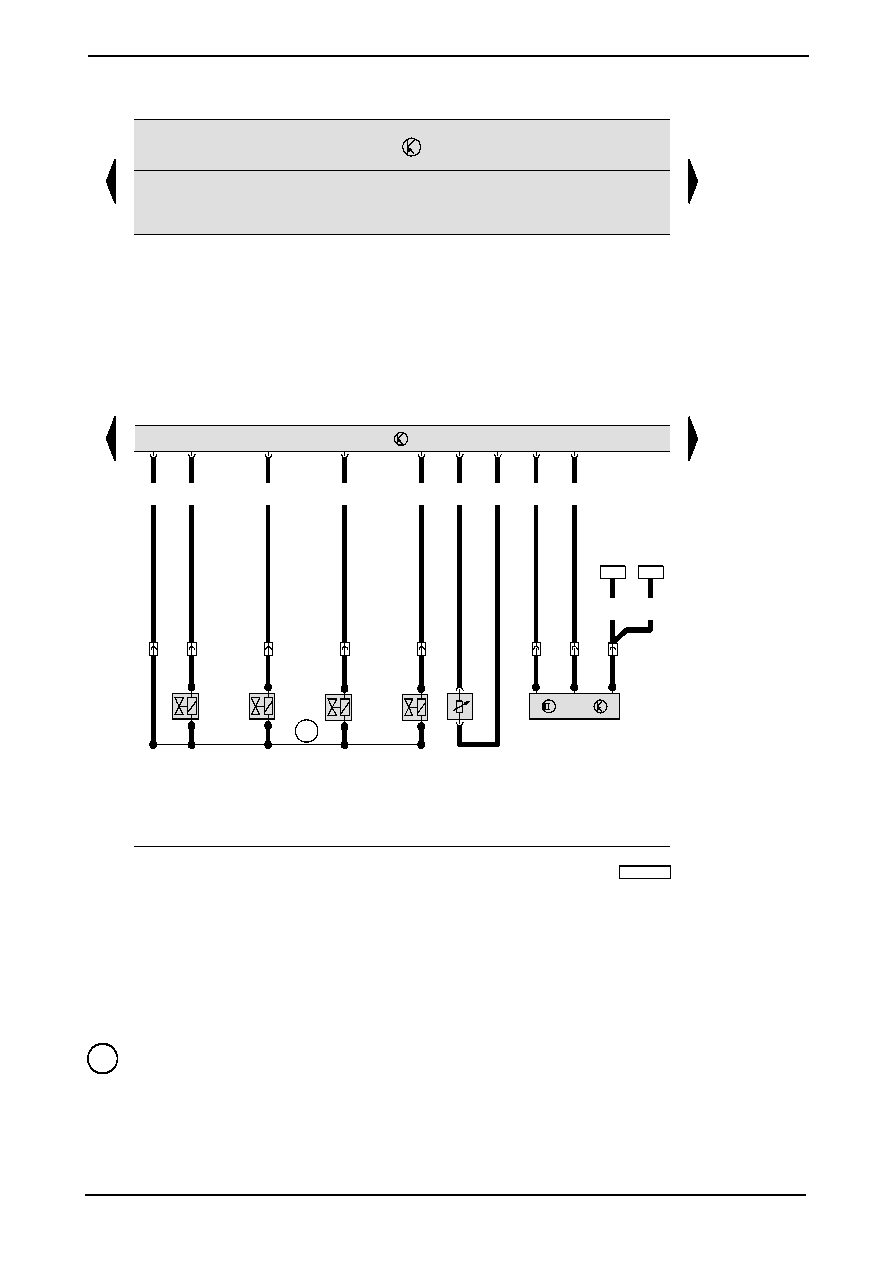
No. 4/2
Ibiza
Battery, starter motor, alternator, voltage regulator, fueseholder/battery
A
-- Battery
B
-- Starter motor
C
-- Alternator
C1
-- Voltage regulator
D
-- Ignition and starter switch
S162 -- Fuse --1-- (30) fuse holder/battery
S163 -- Fuse --2-- (30) fuse holder/battery
S176 -- Fuse --4-- (30) fuse holder/battery
T2j
-- Connector in the gearbox mounting
T3
-- Connector in the front, to the left (grey)
T6d
-- Connector in the front, to the left (blue)
T11a -- Connector in the front, to the left (white)
T12a -
Connector in the front, to the left (white)
T18 -
Connector in the vehicle voltage control unit (brown)
1
-
Earth strap, battery - bodywork
2
-- Earth strap, gearbox - bodywork
P1
-
Positive connection (30), in the fuse holder/battery
*
-- Only vehicles with automatic gearbox
T6ab/5
T6ab/1
15
16
17
18
19
20
21
22
23
24
25
26
27
28
97--42651
T121/42
T121/18
2c/1
T
111
J
52
2c/2
T
sw
2.5
sw
2.5
bl
0.5
ro/ws
6
6x/5
T
6x/4
T
ro/ws
2.5
ro/sw
2.5
ro/ws
2.5
ro/ws
2.5
11a/
T
ge/bl
0.35
ro/ws
0.35
T6ab/3
T6ab/2
11
ro
6
6x/3
T
6x/2
T
6
ro
4
T121/38
111
4
bl/ge
0.35
li/gn
0.35
J
248
T121/62
T121/81
T121/
61
D103
ro/bl
0.35
bl/sw
0.5
li/ws
0.35
br/ws
0.35
bl/sw
0.5
bl/sw
0.5
N
75
5
3
N
18
6
4
Q
6
N
239
2
1
ro
2.5
ro
2.5
ro
2.5
ro
2.5
3
85
30
86
87
bl/sw
1.5
102
bl/sw
1
14/6
T
bl/sw
0.5
bl/sw
0.5
120
56
*
**
A52
3
1
2
2
3
1
2
3
1
A151
D78
Edition 11.01
BJA24807010001
Current flow diagrams
ws = white
sw = black
ro = red
br = brown
gn = green
bl = blue
gr = grey
li
= purple
ge = yellow
or = orange
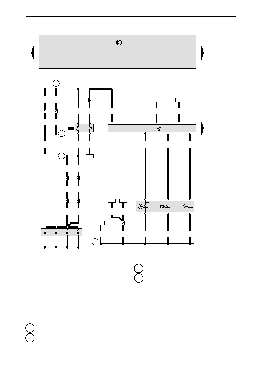
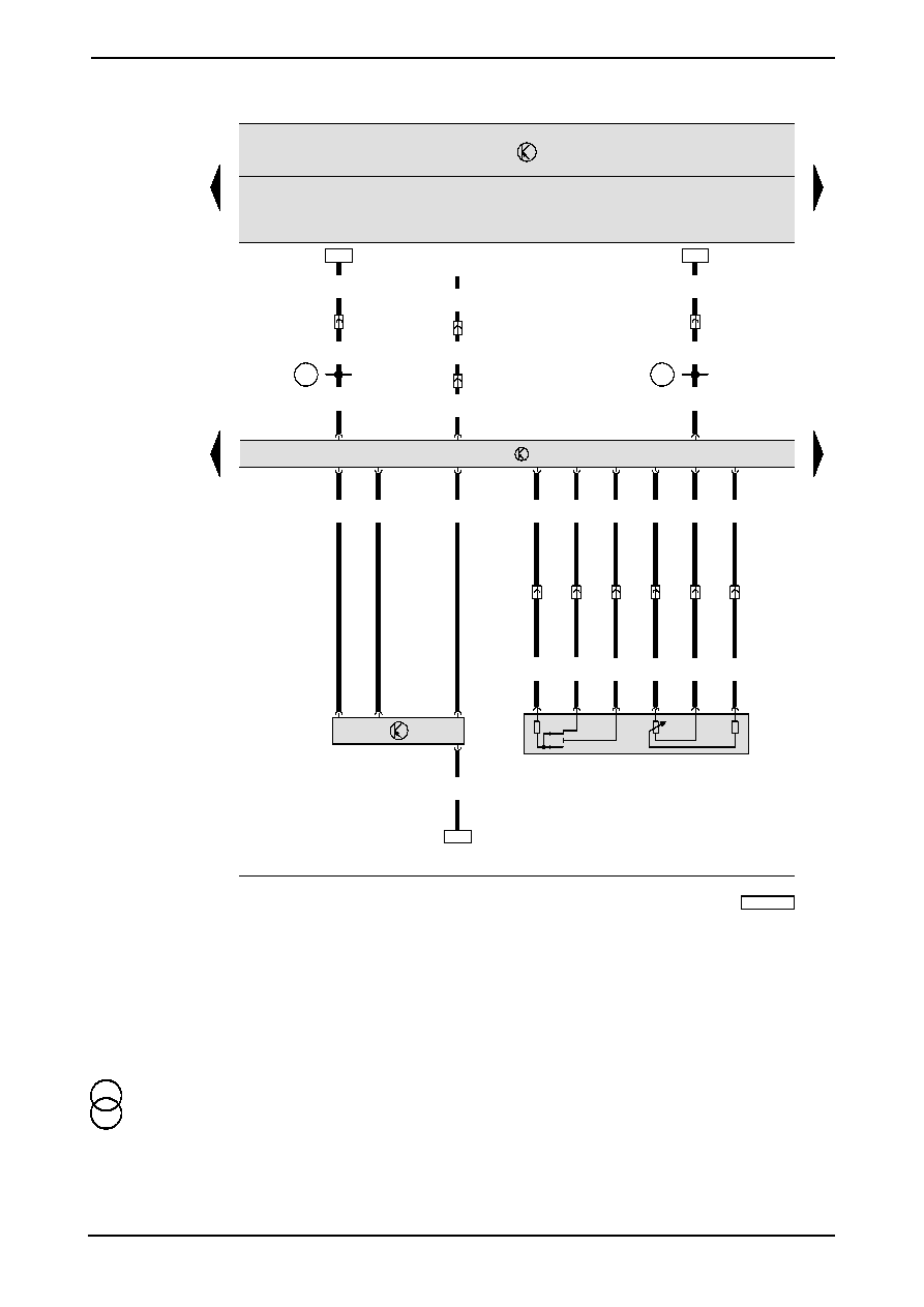
Ibiza
No. 4/3
Direct diesel injection control unit, preheating elements relay, preheating elements (engine), exhaust gas recirculation
valve
J52
-- Glow plug relay
J248 -- Direct diesel injection control unit
N18 -- Exhaust gas recirculation valve
N75 -- Solenoid valve to limit charging pressure
N239 -- Intake manifold flap change--over valve
Q6
-- Preheating elements (engine)
T2c
-- Connector in the engine compartment, to the left
(black)
T6x
-- Connector in the front, to the left (grey)
T11a -
Connector in the front, to the left (white)
T14 -
Connector in the engine compartment, to the left
(black)
A52 -- Positive connection -2- (30), instrument panel wiring
harness
A151
-- Connection -4- (87), in instrument panel wiring
harness
D78 -- Positive connection --1-- (30a), engine bay wiring
harness
D103
-- Connection -3-, engine bay wiring harness
*
-- Only vehicles with additional heating
**
-- Only vehicles without additional heating
29
30
31
32
33
34
35
36
37
38
39
40
41
42
97-42652
J
248
T121/
110
3e/2
T
3e/1
T
T121/102
G
62
2
1
3e/3
T
T121/71
T121/
52
T121/112
T121/104
T121/
73
T121/
31
G
72
2
G
71
3
4
1
T121/80
108
G
28
bl/ro
0.35
bl/ro
0.35
br/bl
0.35
br/sw
0.35
bl/sw
0.35
li/ro
0.35
sw/ge
0.35
ws
0.35
br/bl
0.35
br
0.35
sw
0.35
T121/37
sw/bl
0.35
100
11/9
T
sw/bl
1
bl/ro
0.35
6f/6
T
T121/11
br/gn
0.35
11a/2
T
bl
0.5
J
69
T9f/6
*
*
200
Edition 11.01
BJA24807010001
Current flow diagrams
ws = white
sw = black
ro = red
br = brown
gn = green
bl = blue
gr = grey
li
= purple
ge = yellow
or = orange
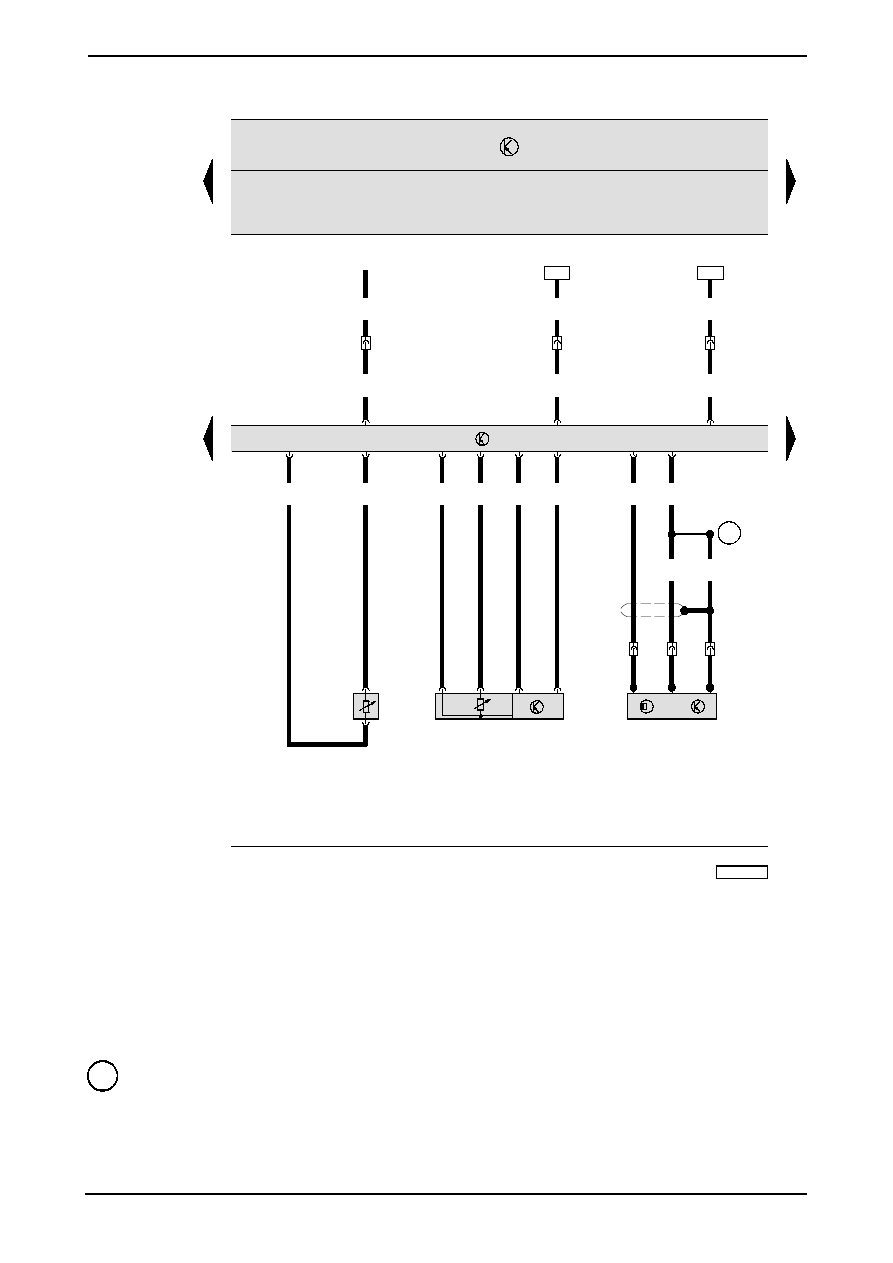
No. 4/4
Ibiza
Diesel direct injection control unit, coolant temperature sender, intake manifold pressure sender, engine revolution sender
G28 -- Engine revolution sender
G62 -- Coolant temperature sender
G71 -- Inlet manifold pressure sender
G72 -- Air intake temperature sender
J69
-- Run--on relay (radiator fan II)
J248 -- Direct diesel injection control unit
T3e
-- Connector in the engine revolution sender
T6f
-- Connector in the front, to the left (brown)
T11
-- Connector in the front, to the left (red)
T11a -- Connector in the front, to the left (white)
200
-- Earth connection (screened), engine bay wiring
harness
*
-- Only vehicleswith engine codes ASZ
43
44
45
46
47
48
49
50
51
52
53
54
55
56
97--42653
J
248
8k/5
T
T121/117
8k/3
T
T121/118
8k/2
T
8k/6
T
T121/
114
T121/116
T121/
103
T121/
121
8k/7
T
T121/
101
T121/109
G
40
G
81
1
2
T121/
111
br/ws
2.5
br/gn
2.5
br/ge
2.5
br/bl
2.5
br/ro
2.5
sw/ge
0.35
li
0.35
br/bl
0.35
3f/3
T
3f/2
T
ws/ge
0.35
3f/1
T
bl/sw
0.5
bl/sw
0.5
119
22
*
N
240
N
241
N
242
N
243
D95
**
Edition 11.01
BJA24807010001
Current flow diagrams
ws = white
sw = black
ro = red
br = brown
gn = green
bl = blue
gr = grey
li
= purple
ge = yellow
or = orange
Ibiza
No. 4/5
Direct diesel injection control unit, pump/injector valves cylinders 1, 2, 3 and 4, fuel temperature sender, hall sender
G40 -- Hall sender
G81 -- Fuel temperature sender
J248 -- Direct diesel injection control unit
N240 -- Pump/injector valve, cylinder 1
N241 -- Pump/injector valve, cylinder 2
N242 -- Pump/injector valve, cylinder 3
N243 -- Pump/injector valve, cylinder 4
T3f
-- Connector in engine bay (black)
T8k
-- Connector in engine bay (red)
D95 -- Connection (injectors) wiring harness engine bay
*
-- Only vehicles with additional heating
**
-- Only vehicles without additional heating
57
58
59
60
61
62
63
64
65
66
67
68
69
70
97-42654
T121/69
11a/6
T
11a/9
T
11b/8
T
T121/
50
11b/9
T
T121/
70
11b/7
T
G
70
4
5
3
T121/30
CAN--L
T121/6
CAN--H
T121/7
100
2
gr/ro
0.35
ro/gn
0.35
gr/ws
0.35
sw/ge
1
F
60
F
8
G
79
T121/
63
11b/
T
T121/
12
11b/
T
11b/6
T
br/bl
0.35
T121/
51
gr/bl
0.35
gn/ws
0.35
gr/ro
0.35
gn/ge
0.35
ws/bl
0.35
br/bl
0.5
gr/bl
0.5
gn/ws
0.5
gr/ro
0.5
gn/ge
0.5
ws/bl
0.5
10
11
D160
D159
or/br
0.35
or/br
0.35
or/br
0.35
or/sw
0.35
or/sw
0.35
or/sw
0.35
135
137
T121/
49
T121/68
6
5
1
3
2
4
KD
SS
J
248
T121/15
gr/ge
0.35
11b/3
T
10b/10
T
F
268
T16/3
gr/ge
0.5
gr/ge
0.5
Edition 11.01
BJA24807010001
Current flow diagrams
ws = white
sw = black
ro = red
br = brown
gn = green
bl = blue
gr = grey
li
= purple
ge = yellow
or = orange
No. 4/6
Ibiza
Direct diesel injection control unit, air mass meter, kick--down switch, idleing switch, accelerator position sender
F8
-- Kick--down switch
F60
-- Idling switch
F268 -- Heating element contact switch, additional heating
G70 -- Air mass meter
G79 -- Accelerator position sender
J248 -- Direct diesel injection control unit
T10b -- Connector behind the dash panel, to the right (black)
T11a -- Connector in the front, to the left (white)
T11b -- Connector in the front, to the left (blue)
D159
-- Connection (High--Bus), engine bay wiring harness
D160
-- Connection (Low--Bus), engine bay wiring harness
97-42655
71
72
73
74
75
76
77
78
79
80
81
82
83
84
J
248
T121/66
T121/32
sw/ro
0.35
D73
T4p/4
T4p/1
T4p/2
T4p/3
F
63
sw/ro
1
11b/4
T
sw/ro
1
B131
sw/ro
1
ro/sw
1
B111
ro/sw
1
99
D101
11b/5
T
bl/ro
1
F
sw/gn
0.35
sw/gn
0.5
sw/gn
0.5
T4m/2
T4m/3
F
36
ws/ro
0.5
6d/1
T
bl/ro
1
A99
104
bl/ro
1
T121/65
T121/14
ws
0.35
11a/10
T
T121/16
ws/ro
0.35
D166
6d/6
T
A76
gr/ws
0.35
gr/ws
0.5
gr/ws
0.5
gr/ws
0.5
T16/7
K
T121/
4
T121/5
br
2.5
br
2.5
131
br
6
29
14/7
T
121
br
2.5
br
2.5
ws
0.35
E
45
90
ro
0.5
Edition 11.01
BJA24807010001
Current flow diagrams
ws = white
sw = black
ro = red
br = brown
gn = green
bl = blue
gr = grey
li
= purple
ge = yellow
or = orange
Ibiza
No. 4/7
Direct injection diesel control unit, brake light switch, clutch pedal switch
E45
-- GRA switch
F
-- Brake light switch
F36
-- Clutch pedal switch
F63
-- Brake pedal switch
J248 -- Direct injection diesel control unit
T6d
-- Connector in the front, to the left (blue)
T11a -- Connector in the front, to the left (white)
T11b -- Connector in the front, to the left (blue)
T14
-- Connector in the engine compartment, to the left
(black)
T16
-- Connector in the glove box on the driver’s side
(diagnostic connection)
29
-- Earth point, in the engine compartment, to the left,
behind the battery (in the telescopic leg)
131
-- Earth connection --2--, engine bay wiring harness
A76 -- Connection (diagnosis cable K), instrument panel
wiring harness
A99 -- Connection -1- (87), in the dash panel insert wiring
harness
B111
-- Positive connection -1- (30a), interior wiring harness
B131
-- Connecion (54), interior wiring harness
D73 -- Positive connection (54), engine bay wiring harness
D101
-- Connection --1--, engine bay wiring harness
D166
-- Connection (diagnostic cable K), engine bay wiring
harness
85
86
87
88
89
90
91
92
93
94
95
96
97
98
97-42656
J
248
T121/2
T121/20
11/10
T
T121/
1
T121/21
T121/
22
A152
ws/li
0.35
ws/li
0.35
T8a/1
R
sw/ge
1.5
ro
0.5
ro
0.5
ro
4
ro
6
TV
2
3
sw/gr
0.35
sw/ws
0.35
11b/
T
11b/1
T
2
sw/bl
0.5
sw/br
0.5
ro
4
ro/ws
6
85
J
359
T6ag/2
T6ag/1
T6ag/3
T6ag/4
J
360
T9c/4
86
T9c/2
30
T9c/6
87
T9c/8
30
86
87
85
sw
4
ws
4
ro
4
3g/1
T
3g/2
T
3g/3
T
ro/ws
4
ro/ws
4
1
2
ro/ge
4
S
276
40A
2
1
2
S
278
40A
ro/ws
4
ro/ws
4
4
ro
10
99
104
105
sw/ge
1.5
2
sw
16
9
1
S
277
40A
*
*
*
ro
0.5
77
Z
35
*
br
10
606
15
14
*
*
1
ro
10
104
Edition 11.01
BJA24807010001
Current flow diagrams
ws = white
sw = black
ro = red
br = brown
gn = green
bl = blue
gr = grey
li
= purple
ge = yellow
or = orange
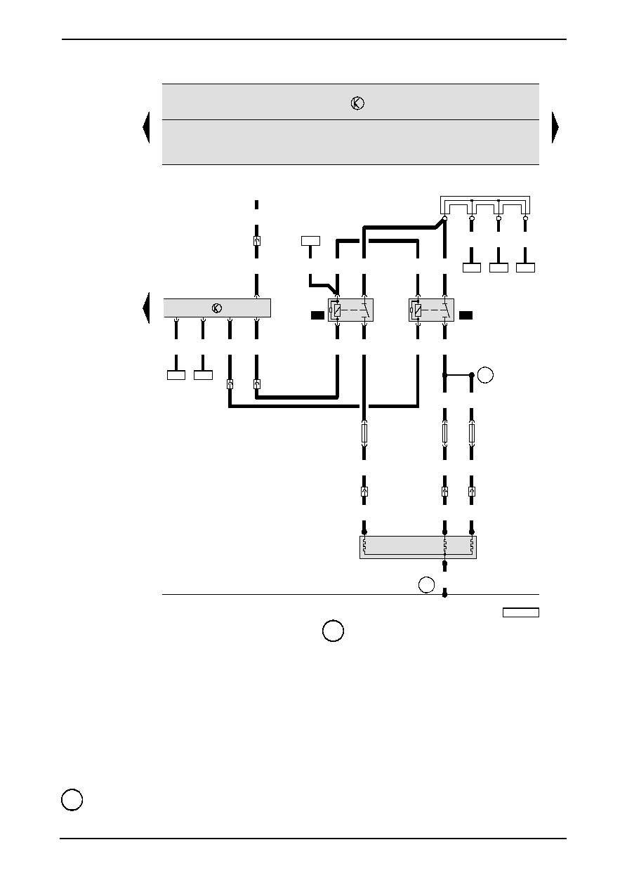
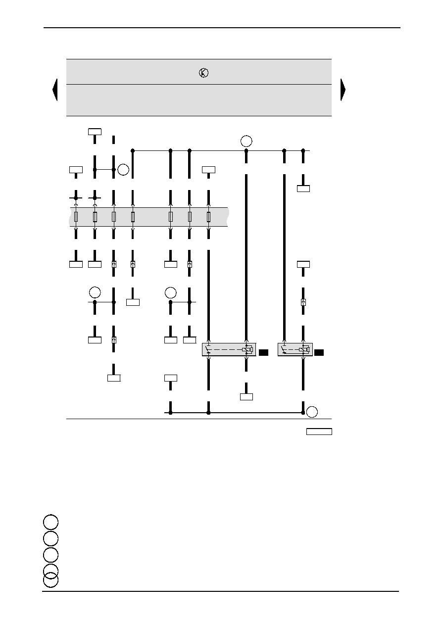
No. 4/8
Ibiza
Direct diesel injection control unit, high temperature relay, low temperature relay, additional heating heater element
J248 -- Direct diesel injection control unit
J359 -- Low temperature relay
J360 -- High temperature relay
R
-- Radio
S276 -- Heater element fuse --1--
S277 -- Heater element fuse --2--
S278 -- Heater element fuse --3--
T3g
-- Connector behind the dash panel (in the PTC heating
element)
T11
-- Connector in the front, to the left (red)
T11b -- Connector in the front, to the left (blue)
TV2 --
Cable distributor for terminal 30
Z35
-- Additional heating heater element
606
-- Earth point, below the central console, near the gear
shift lever
A152
-- Connection -5- (87), in instrument panel wiring
harness
*
-- Only vehicles with additional heating
99
100
101
102
103
104
105
106
107
108
109
110
111
112
97-42657
96
73
25
41
SB
15A
41a
41b
131
J
17
85
T6aa/3
86
T6aa/2
87
T6aa/5
30
T6aa/1
bl/ws
1.5
ro/ge
4
9/T
6/87
bl
1
41
bl/ro
0.35
J
322
2/30
ro
4
ro
2.5
6f/1
T
bl/ge
0.35
bl/ge
0.5
bl
2.5
40
SB
30A
40b
40a
ro/bl
4
4
SB
5A
4b
4a
14
SB
10A
14b
14a
13
SB
5A
13b
13a
26
SB
10A
26b
26a
bl
1
sw/ge
4
3/2
T
sw/ge
4
sw/ge
1.5
sw/ge
1.5
85
86
ro/sw
1
ro
10
78
ro/bl
1
bl/ro
1
sw/ge
1.5
11/2
T
bl/sw
1.5
17
SB
5A
17b
17a
sw
6
sw
2.5
sw
4
A15
D
/15
sw/bl
1
37
bl/sw
1
11/1
T
sw/ge
1
sw/ge
1
sw/ge
1
D52
62
D102
14/11
T
124
sw/ge
0.5
10
13
sw
0.5
114
A101
bl
0.5
19
20
A40
ro
10
97
Edition 11.01
BJA24807010001
Current flow diagrams
ws = white
sw = black
ro = red
br = brown
gn = green
bl = blue
gr = grey
li
= purple
ge = yellow
or = orange
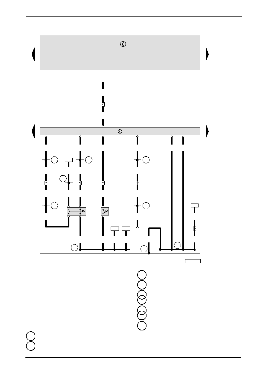
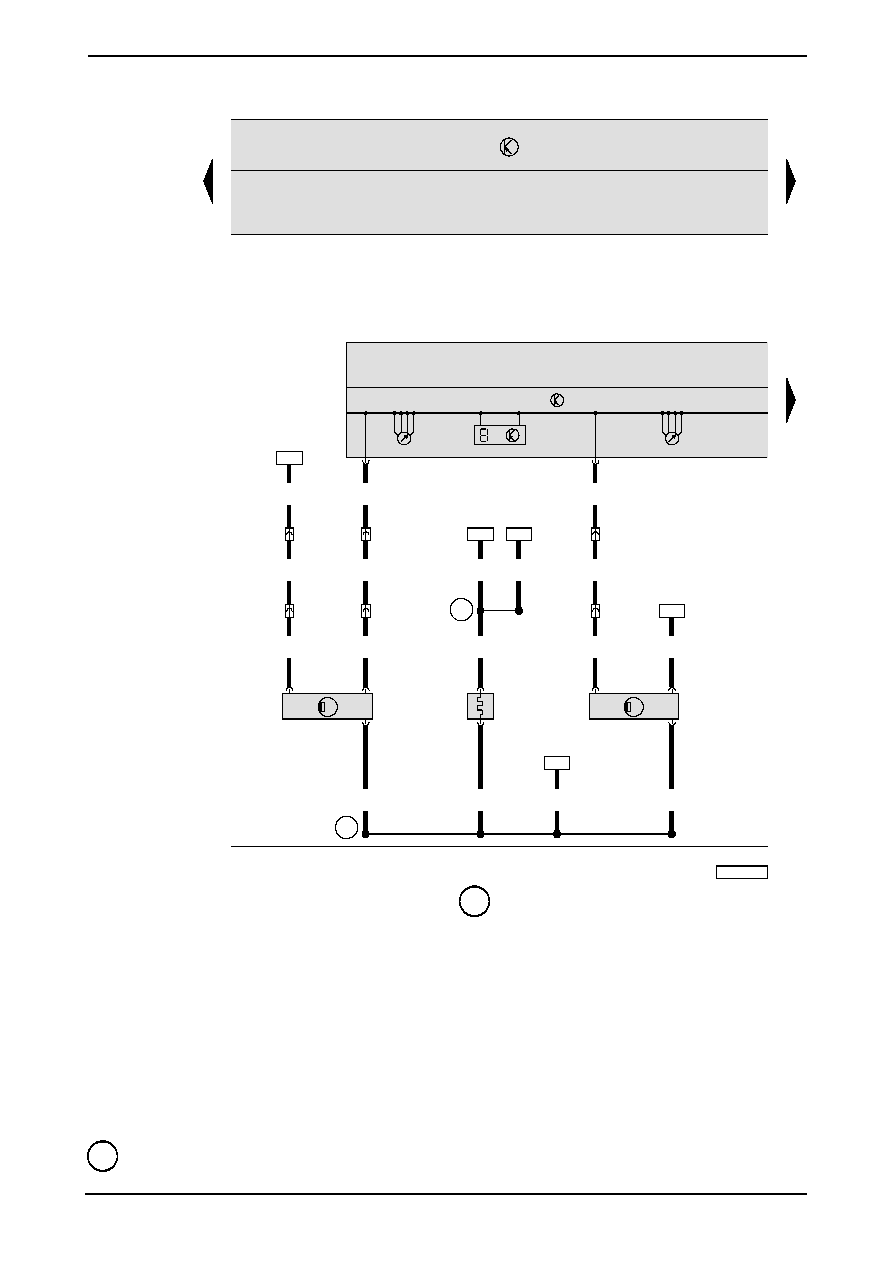
Ibiza
No. 4/9
Direct diesel injection system relay, fuel pump relay
D
-- Ignition and starter switch
J17
-- Fuel pump relay
J322 -- Diesel direct injection system relay
T3
-- Connector in the front, to the left (grey)
T6f
-- Connector in the front, to the left (brown)
T11
-- Connector in the front, to the left (red)
T14
-- Connector in the engine compartment, to the left
(black)
A15 -- Positive connection (15), instrument panel wiring
harness
A40 -- Positive connection -1- (30), in the instrument wiring
harness
A101
-- Connection --3-- (87), in instrument panel wiring
harness
D52 -- Positive connection (15a), engine bay wiring harness
D102
-- Connection --2--, engine bay wiring harness
113
114
115
116
117
118
119
120
121
122
123
124
125
126
97-42658
J
285
G
21
11/11
T
ws/bl
0.35
G
22
3
1
Y
4
K
T32/6
14/10
T
11a/3
T
14/2
T
2
sw
0.5
sw
0.5
sw
0.5
100
T32/4
6a/6
T
gn
0.35
br/gn
0.5
14/12
T
br/gn
0.5
G
266
2
3
1
101
sw/ge
0.5
br
0.5
G
1
br
0.5
ws/ro
0.5
ws/bl
0.5
N
51
1
2
*
br
2.5
55
84
bl/sw
0.5
21
br
0.5
bl/sw
0.5
bl/sw
0.5
D110
D109
Edition 11.01
BJA24807010001
Current flow diagrams
ws = white
sw = black
ro = red
br = brown
gn = green
bl = blue
gr = grey
li
= purple
ge = yellow
or = orange
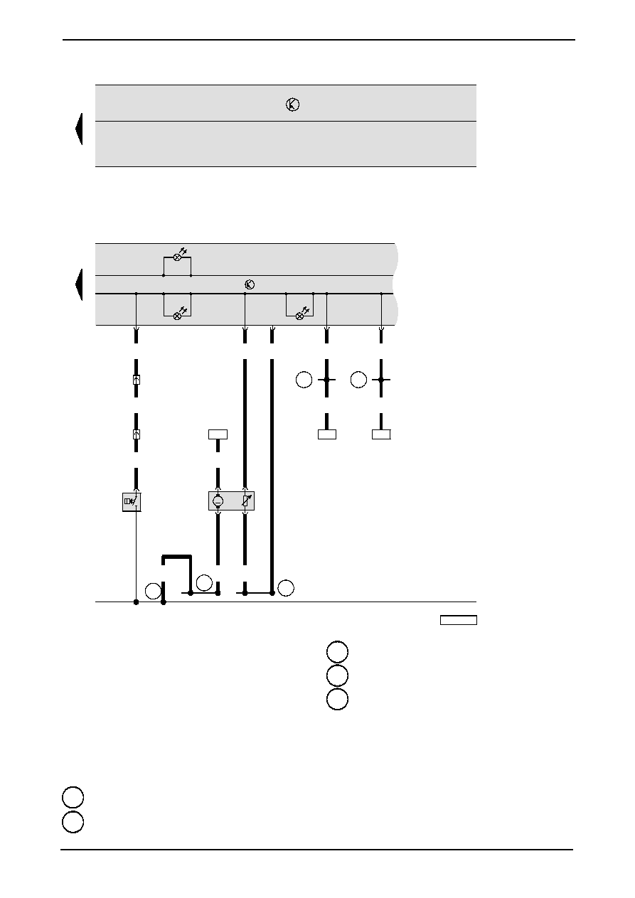
No. 4/10
Ibiza
Dash panel insert, control unit with warning lamps on the instrument panel, speedometer sender, oil level/temperature
sender
G1
-- Fuel gauge
G21 -- Speedometer
G22 -- Speedometer sender
G266 -- Oil level/temperature sender
J285 -- Control unit with warning lamps on the dash panel
insert
K
-- Dash panel insert
N51 -- Intake manifold preheating heater element
T6a
-- Connector in the front, to the left (green)
T11
-- Connector in the front, to the left (red)
T11a -- Connector in the front, to the left (white)
T14
-- Connector in the engine compartment, to the left
(black)
Y4
-- Odometer
D109
-- Connection -7-, engine bay wiring harness
D110
-- Connection -8-, engine bay wiring harness
*
-- Only vehicles with additional heating
127
128
129
130
131
132
133
134
135
136
137
138
139
140
97-42659
269
F
1
1
11/4
T
gn/sw
0.35
gn/sw
0.5
14/1
T
sw/gn/sw
0.5
li/sw
0.35
br/ws
0.5
br
1.5
bl/ws
1.5
106
or/br
0.35
or/sw
0.35
A122
A121
or/br
0.35
or/sw
0.35
59
68
J
285
K
3
K
105
K
29
K
T32/23
T32/15
T32/7
T32/8
CANL
CANH
T32/32
br/ws
0.35
51
249
br
4
G
6
G
1
3
4
2
M
Edition 11.01
BJA24807010001
Current flow diagrams
ws = white
sw = black
ro = red
br = brown
gn = green
bl = blue
gr = grey
li
= purple
ge = yellow
or = orange
Ibiza
No. 4/11
Dash panel insert, control unit with warning lamps on the instrument panel, fuel level sender, fuel pump, oil pressure
switch
F1
-- Oil pressure switch
G
-- Fuel level indicator sender
G6
-- Fuel pump (pre--supply pump)
J285 -- Control unit with warning lamps on the instrument
panel
K
-- Dash panel insert
K3
-- Alternator warning lamp
K29 -- Glow period warning lamp
K105 -- Reserve fuel warning lamp
T11
-- Connector in the front, to the left (red)
T14
-- Connector in the engine compartment, to the left
(black)
51
-- Earth point, boot, on the right
249
-- Earth connection -2-, interior wiring harness
269
-- Earth connection --1--, in the instrument panel wiring
harness
A121
-- Connection (High--Bus), instrument panel wiring
harness
A122
-- Connection (Low--Bus), instrument panel wiring
harness
Wyszukiwarka
Podobne podstrony:
Instalacja elektryczna fiesta mk5 99 02
Ursus C330 schemat instalacji elektrycznej
Schemat instalacji elektrycznej Vivaro MJ06
SUBARU LEGACY 1990 schematy instalacji elektrycznej
Lupo schemat instalacji elektrycznej 2
ZETOR 7520 10540 schemat instalacji elektrycznej[PL]
Schemat instalacji elektrycznej Vivaro MJ05
schemat instalacji elektrycznej CZ 501 502 505
Instalacja elektryczna fiesta mk5 99 02
Schemat instalacji elektrycznej Vivaro MJ04
Schemat instalacji elektrycznej SJ 410
bhp przy urządzwniach i instalacjach elektrycznych projekt 15 02 12
Urządzenia i instalacje elektryczne w przestrzeniach zagrożonych wybuchem
więcej podobnych podstron