year as our skills and habits shift.
I’ve watched the table saw take flag-
ship status from the radial arm, and
have seen more weekend warriors
outfit their shops with air compres-
sors, dust collectors, and other stuff
that used to be standard issue for
professional shops only.
Manufacturers ushered in a lot of
these changes with new tools like
the portable thickness planer and
sliding miter saw, that put big wood-
working capabilities into smaller
and more affordable packages.
I’ll try to take advantage of
improvements like these when I
can, but since I’m always on speak-
ing terms with the evil twins of
small-shop woodworking — Not
Enough Money, and Not Enough
Space — I still have to invent home-
spun solutions from time to time.
A while back it was a portable
miter saw station (also available
from PlansNOW). I don’t travel to
job sites the way contractors do, but
the portable design of that worksta-
tion does make it easier to store and
to haul around my house for a pro-
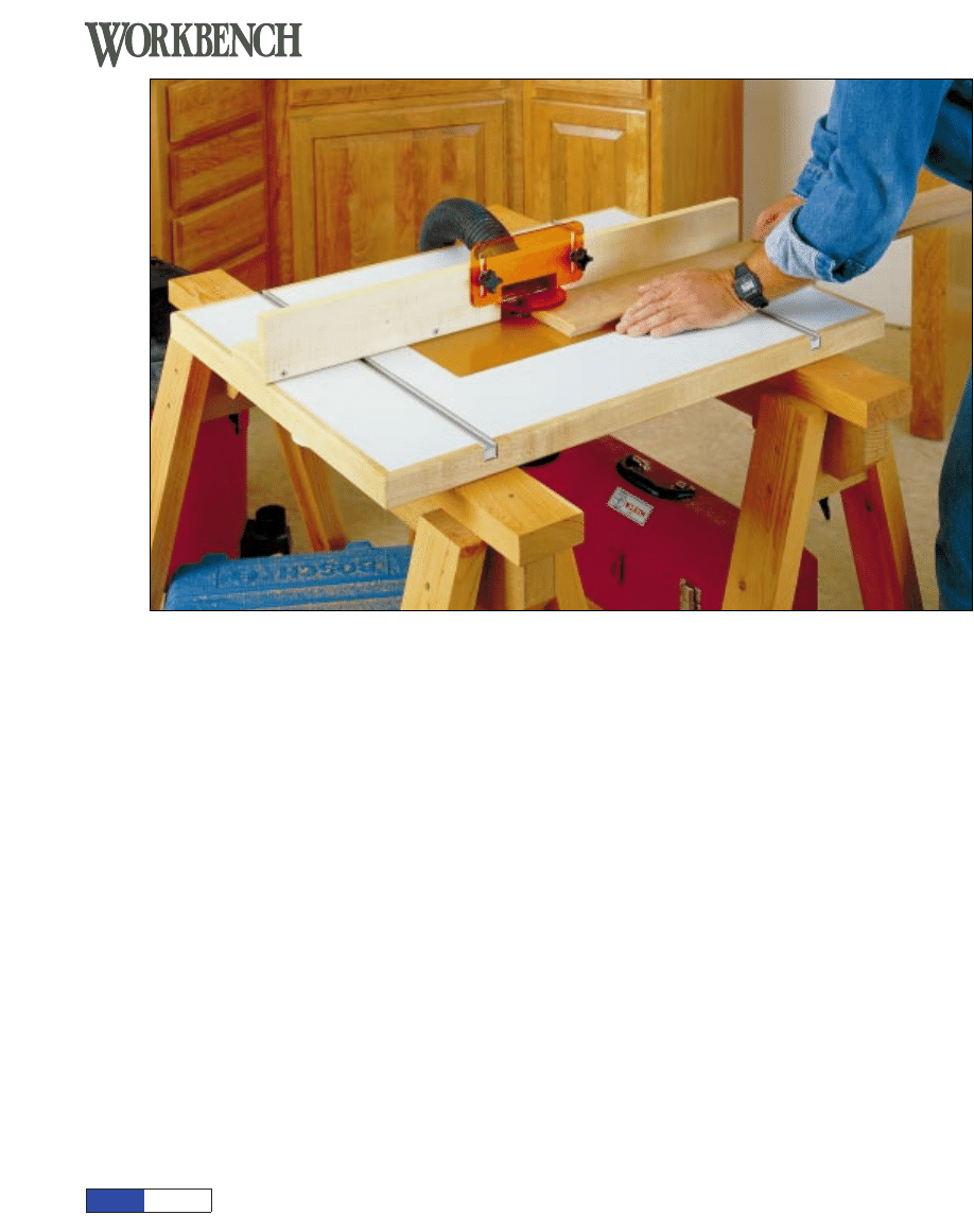
ject. This router table shares a simi-
lar platform design (it’s supported
by the same pair of sawhorses), but
I didn’t want the portability to come
at the expense of other features.
Happily, it didn’t have to — I still
ended up with a table big enough to
support large workpieces, an
adjustable fence with a dust extrac-
tion port, a cutter guard, and alu-
minum T-slot tracks for mounting
the fence and just about any jig I’d
ever want to use (Router Table
Construction View). I figured
that’s plenty in one package. If I
don’t limit my wish list of features, I
can get carried away and over-engi-
neer an otherwise simple project.
Keeping It Simple
I’ve seen my share of fancy router
tables, some with elaborate joinery
and base cabinets outfitted for stor-
ing bits and accessories. It’s not that
I don’t like them, but the trade-offs
— losing that floor space perma-
nently, and giving up an awful lot of
time to build one — make a simple
design much more practical for me.
For portability, basic is usually best.
Using a double layer of
3
/
4
" ply-
Portable Router Table
Over the past couple of decades
I’ve noticed how home wood-
working shops, including mine,
have evolved. The roster of
“must-have” tools and equip-
ment changes from year to
plans
N O W
page 1
© August Home Publishing Co.
MAGAZINE
from
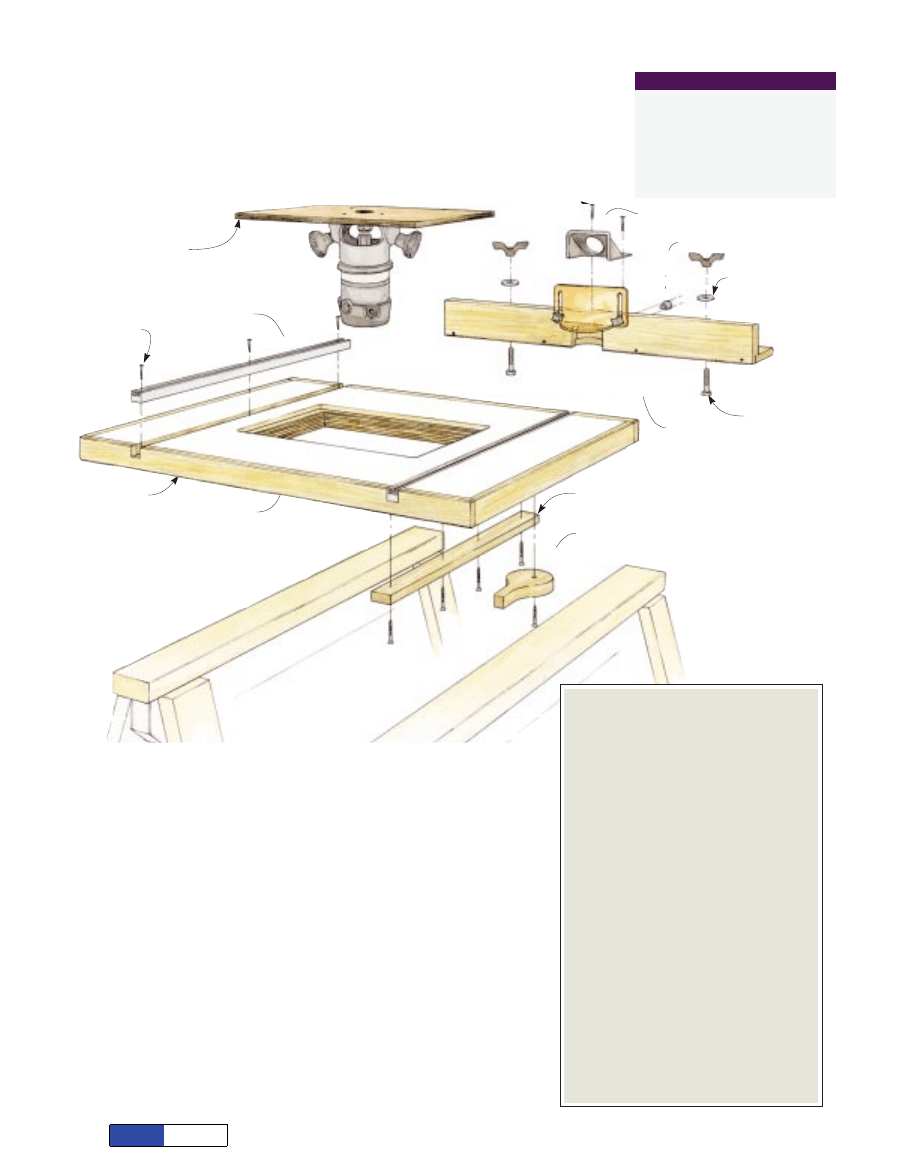
Table insert plate
" x 10 " x 15 "
(phenolic plastic)
#/8
!/4
!/2
T-slot track
" x
" x 24"
(aluminum)
#/4
#/4
Pan-head
sheet-metal screw
#6 x
"
#/4
Pan-head
sheet-metal screw
#6 x
"
#/4
Maple edging
Table platform
(Plywood sandwich covered
on both sides with plastic
laminate, edged with hardwood.)
FHWS
#8 x 1 "
!/4
FHWS
#8 x 1 "
!/2
Cam lever
" x 3" x 5"
#/4
Cleat
" x 1 " x 20"
#/4
!/2
Hex head bolt
" -20 x 1 "
!/4
!/2
Star knob
"-18 with 1"-long
threaded stud.
%/16
Cutter guard
(polycarbonate)
Flat washer
"
!/4
Wing knob
"-20
!/4
T-nut
"-18
(screw-flange type)
%/16
Dust
extraction
hood
wood for the table might seem like
overkill, but a layered top makes a
lot of sense for a project like this.
First, it adds strength and weight
but not bulk, so it helps dampen the
router’s vibration without sacrific-
ing the table’s portability. Second,
it’s more stable, especially since I
covered it top and bottom with plas-
tic laminate. The high-pressure lam-
inate makes for a durable and low-
friction work surface. Don’t suc-
cumb to temptation and cover only
the top of the table — an exposed
underside will react a lot more to
changes in humidity, making it
almost impossible for the platform
to stay flat over time.
Fix Yourself a Sandwich
As with most projects, the building
process for this one flows easier if
you start with the big stuff and end
with the details. I began by cutting
the plywood for the “sandwich” top.
Normally I’d treat the assembly of
the platform — cutting and gluing
up the plywood, and covering it with
laminate — as two separate proce-
dures, but it actually works better to
mix them up a bit in this case.
Because I applied hardwood edging
to the platform, I needed the two
plywood panels to be exactly the
same size and aligned with their
edges perfectly flush. As it turns
out, I used my laminate-trimming
tools and techniques to do this.
Router Table Construction View
OVERALL SIZE: 5
3
/
4
"H ×24"W × 32"L
What You’ll Need
Lumber
(1) Half-sheet of
3
/
4
" plywood
(1) Half-sheet of plastic laminate
(10) lin. ft. of
1
/
2
" × 1
1
/
2
" maple
(9) lin. ft. of
3
/
4
" × 3
1
/
2
" maple
Hardware
(1) Insert plate
3
/
8
" × 10
1
/
4
" × 15
1
/
2
"
(1) Cutter guard (polycarbonate)
(1) Dust extraction hood
(2)
3
/
4
" ×
3
/
4
" × 24" T-slot tracks
(2)
1
/
4
"-20 wing knobs
(2)
5
/
16
"-18 star knobs w/ 1" stud
(2)
1
/
4
"-20 × 1
1
/
2
" hex-head bolts
(2)
5
/
16
"-18 T-nuts with #4 screws
(2)
1
/
4
" flat washers
(2)
5
/
16
" flat washers
(6) #6 ×
3
/
4
" pan-head sheet metal screws
(2) #8 ×
3
/
4
" pan-head sheet metal screws
(25) #8 × 1
1
/
4
" flat-head wood screws
(2) #8 × 1
1
/
2
" flat-head wood screws
Portable router table
A kit has been assembled for this pro-
ject that includes the accessories, hard-
ware, and fasteners listed below.
Order #3307100.
To order, call Workbench at (800) 311-3994.
WORKBENCH PROJECT SUPPLIES
plans
N O W
page 2
© August Home Publishing Co.
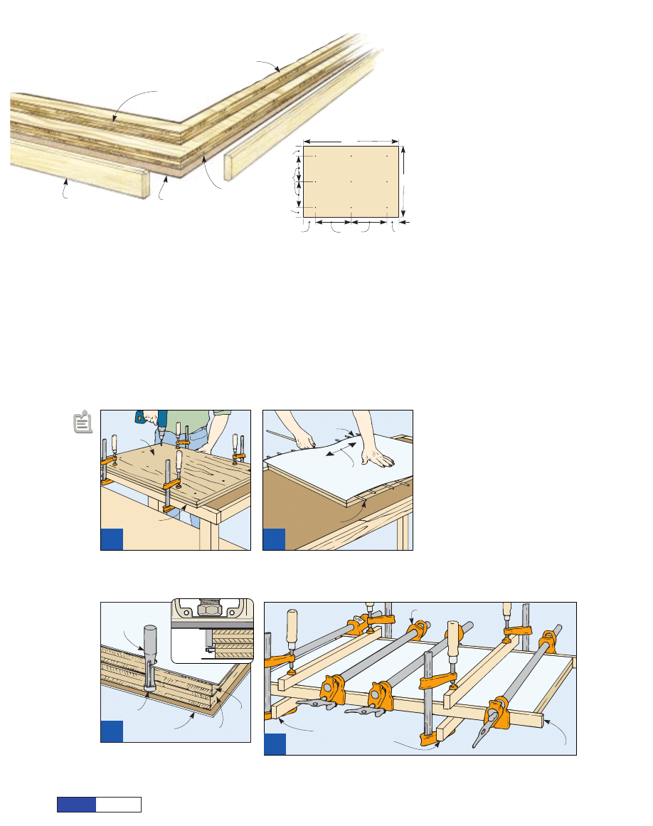
Maple edging
" x 1 ",
cut to length.
!/2
!/2
Bottom layer
(plastic laminate)
Bottom panel
" x 23" x 31"
#/4
Top panel
" x 23 " x 31 "
(plywood)
#/4
!/4
!/4
Top layer
(plastic laminate)
Plastic
laminate
Press from
center out.
Use wood dowels
or slats for spacers;
remove one at a time.
2
W
Wh
heen
n tth
hee cco
on
ntta
acctt cceem
meen
ntt o
on
n tth
hee lla
am
miin
na
attee
a
an
nd
d p
pllyyw
wo
oo
od
d iiss d
drryy,, p
po
ossiittiio
on
n tth
heem
m w
wiitth
h
ssp
pa
acceerrss iin
n b
beettw
weeeen
n,, tth
heen
n p
prreessss iin
ntto
o p
plla
accee..
Start by cutting one plywood
panel to the required 23" × 31" size.
Mark this as the bottom panel, then
drill and countersink for the screws
that attach it to the top panel
(Laminated Top Assembly View
and Fastener Layout Detail).
Next, cut the top plywood panel to
23
1
/
4
" × 31
1
/
4
", so it will overhang
the bottom panel by about
1
/
8
" along
each edge. Use a bench top or other
flat surface as a base to glue and
clamp the assembly upside-down,
then fasten the panels together with
screws (Figure 1). Check to make
sure all the screw heads are fully
countersunk, and give the glue
some time to set up — an hour
should do it.
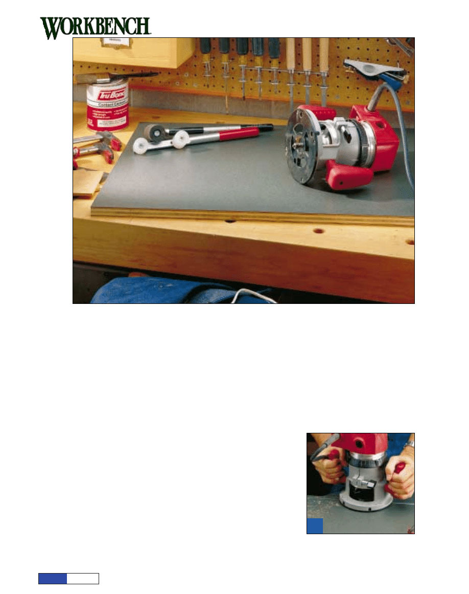
Bring on the Laminate
We recently detailed the basic steps
involved in applying plastic lami-
nates (see
Laying Laminates
at the
end of this article), but I can outline
the process here.
First, cut two laminate pieces
slightly larger than the plywood,
say an extra inch along each edge.
Then brush a couple of coats of con-
tact cement on one piece of lami-
nate and on one face of the plywood
sandwich, and set each aside to dry.
When the adhesive has dried to a
slight tack, use wood spacers or
dowels to separate the coated sur-
faces while you position the lami-
nate. Then press the laminate down
as you remove the spacers, working
from the center of the panel out
(Figure 2). Use pressure from a
roller or a wooden block and ham-
mer to seat the laminate. Then turn
the platform over and apply contact
cement to the other plywood face
and the second piece of laminate.
Allow drying time, then apply the
other laminate piece the same way.
With the top and bottom surfaces
laminated, you can use a router to
do the trimming. This technique
requires trimming the laminate and
the oversize plywood piece at the
same time, which will be too much
for a typical
1
/
4
"-shank laminate trim
bit. You’ll fare better here using a
flush-trim bit with a
1
/
2
" shank and
1"-long carbide flutes. Make the
first pass with the platform top-side
up (Figure 3). Then flip the sand-
wich over to trim the bottom lami-
nate flush with the plywood.
Done properly, this simple tech-
nique gives you an assembly of four
layers, all perfectly sized and
aligned with each other.
Flush trim bit with
" shank
!/2
Laminate on
underside
Guide
bearing
Bottom
Top
3
R
Ro
ou
utt tth
hee u
up
pp
peerr lla
am
miin
na
attee a
an
nd
d tto
op
p p
pllyyw
wo
oo
od
d
lla
ayyeerr ffllu
ussh
h w
wiitth
h tth
hee llo
ow
weerr p
pllyyw
wo
oo
od
d.. T
Th
heen
n
fflliip
p tth
hee tta
ab
bllee tto
o ttrriim
m tth
hee b
bo
otttto
om
m lla
am
miin
na
attee..
Clamp every 12" or less.
Overhang will
cover edging on ends.
“Keepers” prevent edging from
shifting during glue-up.
4
C
Clla
am
mp
p sso
om
mee ““kkeeeep
peerr”” b
bo
oa
arrd
dss iin
n p
plla
accee tto
o h
ho
olld
d tth
hee h
ha
arrd
dw
wo
oo
od
d eed
dggiin
ngg ffllu
ussh
h w
wiitth
h tth
hee lla
am
mii--
n
na
attee ssu
urrffa
acceess.. D
Do
o tth
hee ffrro
on
ntt a
an
nd
d rreea
arr eed
dggeess ffiirrsstt,, a
allllo
ow
wiin
ngg a
a
9
9
//
1
16
6
"" o
ovveerrh
ha
an
ngg a
att eea
acch
h een
nd
d..
Clamp
plywood layers
to flat bench top.
Bottom
panel
1
U
Ussiin
ngg a
a fflla
att b
been
ncch
h tto
op
p a
ass a
a rreeffeerreen
nccee ssu
urr--
ffa
accee,, ggllu
uee a
an
nd
d ssccrreew
w tth
hee ttw
wo
o lla
ayyeerrss o
off
3
3
//
4
4
""
p
pllyyw
wo
oo
od
d tto
oggeetth
heerr ffo
orr tth
hee p
plla
attffo
orrm
m..
Laminated Top
Assembly View
11 "
%/8
Bottom
plywood
panel
8 "
!/2
3 "
&/8
3 "
&/8
23"
31"
3"
3"
Fastener
Layout Detail
plans
N O W
page 3
© August Home Publishing Co.
Banding the Edges
Now that you’ve managed to get all
those crisp, square edges on your
laminated assembly, you’ll want to
protect them with solid wood edg-
ing. I ripped some
1
/
2
"-thick hard
maple for this. When you cut this
stock to length, the end pieces
should be 23" (equal to the width of
the plywood), and the front and
back edging should be 32
1
/
8
" (the
plywood length plus 1
1
/
8
"). The
extra length is for the overlap
where the ends of the edging pieces
butt together, plus a margin to trim.
To make sure the edging didn’t
creep under clamping pressure, I
clamped some 1x “keepers” on both
the top and bottom of the platform
(Figure 4). Apply the front and
back edging first, leaving
9
/
16
"
exposed at each end. If you want to
pull the clamps off sooner, you can
drill and drive some screws to hold
the edging in place, but glue alone
will hold fine once it sets up.
If the wood edging sneaks above
the laminate surface during glue-
up, you can sand it flush with a rab-
beted sanding block (Pro Tip).
The vertical face of the block keeps
the 90° angle intact while the nar-
row ledge automatically limits the
sanding area. That way you can’t
overreach and scratch the laminate.
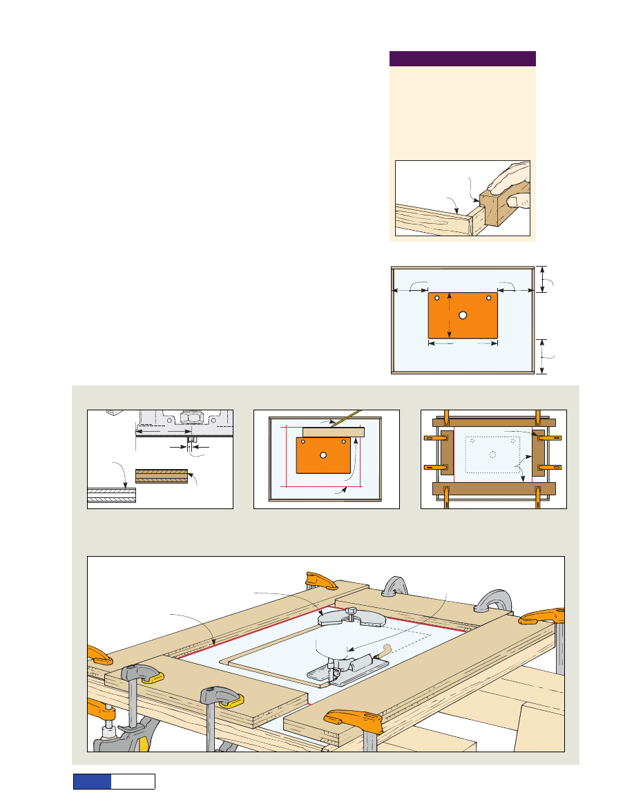
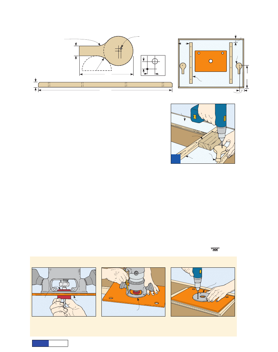
Adding the Insert Plate
Once I’d cleaned up the edging, I
routed an outline in the top for the
3
/
8
"-thick phenolic plastic insert. I
installed it toward the rear of the
table to give me a larger support
area in front of the cutter, though
you can vary this to your preference
(Insert Position Detail).
I’ve seen a lot of different meth-
ods for making the opening and
ledge for the table insert, and you
may have a favorite. If not, the tech-
nique shown below provides accu-
rate results without much fuss
(Insert Installation Procedure).
8 "
!/4
8 "
!/4
7 "
#/4
6"
10 "
!/4
15 "
!/2
Front
Insert Position Detail
PRO TIP
Sanding Block for Edges
Cut a rabbeted block to sand the
edging flush without scratching
the laminate. Spray adhesive will
bond sandpaper onto the ledge,
and you can trim it with a knife.
Rabbeted block limits
reach of sandpaper.
Wood edging
Insert Installation Procedure
Step D: Rout
"-wide x
"-deep
groove, keeping router base
against guide boards.
!/2
#/8
Index line
Step E: Use a jig saw to cut
along inside edge of groove to
remove center waste.
Gauge board
Index line
Pencil
Guide boards
Clamp
R
r
Guide
board
Gauge board
(width=R minus r)
S
Stteep
p A
A:: S
Su
ub
bttrra
acctt tth
hee b
biitt rra
ad
diiu
uss ((rr)) ffrro
om
m
tth
hee rro
ou
utteerr b
ba
assee rra
ad
diiu
uss ((R
R)) tto
o ggeett tth
hee
w
wiid
dtth
h o
off yyo
ou
urr gga
au
uggee b
bo
oa
arrd
d..
S
Stteep
p B
B:: P
Po
ossiittiio
on
n tth
hee iin
nsseerrtt o
on
n tth
hee tta
ab
bllee
w
wiitth
h d
do
ou
ub
bllee--ssiid
deed
d tta
ap
pee a
an
nd
d u
ussee tth
hee gga
au
uggee
b
bo
oa
arrd
d tto
o m
ma
arrkk iin
nd
deexx lliin
neess a
arro
ou
un
nd
d iitt..
S
Stteep
p C
C:: C
Clla
am
mp
p ggu
uiid
dee b
bo
oa
arrd
dss iin
n p
plla
accee
a
allo
on
ngg tth
hee iin
nd
deexx lliin
neess.. S
Sm
ma
allll gga
ap
pss a
att tth
hee
cco
orrn
neerrss w
wo
on
n’’tt a
affffeecctt rro
ou
utteerr ttrra
avveell..
plans
N O W
page 4
© August Home Publishing Co.
Wing knob
"-20
!/4
Washer
"
!/4
Hex-head bolt
"-20 x 1 "
!/4
!/2
FHWS
#8 x 1 "
!/4
Fence
Guard
Washer
"
%/16
Star knob
"-18
%/16
T-nut
"
%/16
PHSMS
#4 x
"
#/8
FHWS
#8 x 1 "
!/4
PHSMS
#8 x
"
#/4
Dust
hood
Base
Installing the T-tracks
Before you set your router aside
you can cut the dadoes for the alu-
minum T-tracks. This hardware
makes the fence adjustment easy
and reliable, plus it lets you mount
featherboards and other acces-
sories with a minimum of setup.
A single board clamped in place
would do for a guide, but I wanted
a method that prevented the router
from moving off the intended cut.
To do this, I built a simple jig that
keeps the router base captive on
two sides (A Jig for Routing
Accurate Dadoes). Using a
1
/
2
"
bit for the first passes, and then a
3
/
4
" bit for the final pass, reduces
the chance of chipping out the lam-
inate. When both dadoes are rout-
ed, screw the T-tracks in place.
Adding a Versatile Fence
Like the rest of this project, the
fence I designed is textbook simple
but has the features I wanted
(Fence Assembly View, Fence
Assembly Details). I found off-
the-shelf components for the guard
and dust-extraction hood, so the
fence body itself, the base, and two
corner braces are the only wood
components I needed to fabricate.
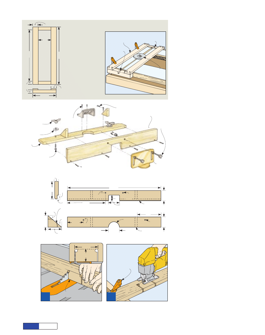
Aside from cutting the pieces to
size and drilling for hardware, the
only real machining for the fence
involves making the opening
(called the throat) that provides
clearance for the router bits. I
made layout marks on the fence,
drilled a
1
/
2
" hole inside each cor-
ner of the throat opening, and
made the vertical cuts on the table
saw (Figure 5). Then I used a jig
saw to remove the waste piece
(Figure 6). I also used the jig saw
to cut the half-round opening in the
fence base.
After adding those details, a cou-
ple of passes on the table saw will
cut the rabbet along the bottom
rear edge of the fence, and you can
drill and countersink for the assem-
bly screws. You’ll also need holes in
the fence base (for the T-track
bolts) and near the throat opening
for the two studded knobs that
Clamp fence face
to bench top.
6
A
A jjiigg ssa
aw
w w
wiillll m
ma
akkee ssh
ho
orrtt w
wo
orrkk o
off tth
hee lla
asstt
ccu
utt ffo
orr tth
hee tth
hrro
oa
att o
op
peen
niin
ngg iin
n ffrro
on
ntt o
off tth
hee
ffeen
nccee,, a
an
nd
d o
off tth
hee ccu
utto
ou
utt iin
n tth
hee b
ba
assee..
Fence body,
guided by miter gauge.
5
A
Afftteerr d
drriilllliin
ngg h
ho
olleess tto
o m
ma
arrkk tth
hee cco
orrn
neerrss o
off
tth
hee ffeen
nccee’’ss tth
hrro
oa
att o
op
peen
niin
ngg,, m
ma
akkee tth
hee vveerrttii--
cca
all ccu
uttss o
on
n tth
hee tta
ab
bllee ssa
aw
w..
32"
3 "
!/2
3 "
!/2
3 "
#/4
!/4" chamfer
#/4"
1 "
!/4
13"
5 "
!/2
2"
3 "
#/4
8"
Brace location
%/16"-dia.
hole
1 "
radius
&/8
#/8"-dia.
hole
#/4"
#/4"
3 "
!/2
!/4"
3 "
!/4
#/4"
Counterbore and drill
for mounting screws.
#/4"
2
#/4"
27"
24"
11"
2 "
!/2
6"
2 "
!/2
1 "
!/2
Fence
Assembly View
A Jig for Routing Accurate Dadoes
Align jig with
end of table top.
Router stays
captive in jig.
!/2" dado
roughed in.
#/4" finished
dado
Fence Assembly Details
3 "
#/4
2"
Note: This jig is made
using scrap 2x2 stock
for the ends and
" x 2 "
material for the sides. It is
sized to fit a 6"-diameter
router base. Measure your
router base and make the
jig to fit. When using the jig,
rough out the dadoes with
a
" straight bit, then
make the final pass with
a
" bit.
!/2
!/2
!/2
#/4
F
Feen
nccee
(Front View)
F
Feen
nccee
(End View)
B
Brra
accee
(Side View)
B
Ba
assee (Top View)
plans
N O W
page 5
© August Home Publishing Co.
secure the guard. To accommodate
those threaded studs, I used
5
/
16
"
T-nuts installed through the back
of the fence. I built my fence using
hard maple, so instead of trying to
pound in a pronged T-nut I used the
screw-flange type, which installs
more easily in really dense woods.
To get the small triangular
braces, I used a miter saw and cut
them off the end of a longer board.
After drilling them for screws, I
glued up the fence assembly and
fastened everything together.
Before I mounted the fence and
got ready to use the table, I still had
a couple of details to take care of.
First, I had to make and install the
cleats and cam levers on the under-
side of the table (Cleat and Cam
Lever Details). The cleats help
establish the placement of the
sawhorses under the table, and the
cam levers provide pressure
against the sides of the sawhorse
top plates to keep the table from
sliding around. I placed the cleats
near the insert opening, spaced far
enough apart to keep the sawhorse
legs from interfering with each
other. Then I used a scrap 2x4 block
as a spacer and fastened each cam
lever with a screw (Figure 7).
Keeping the cam levers to the out-
side makes them easy to reach, and
by pivoting under the table edge
they remain out of harm’s way
when locked. When they’re
unlocked, the protruding handles
let me know the platform isn’t
secured to the sawhorses.
Mounting the Router
Though a truly concentric router
mount isn’t critical for most work, I
still aimed for precision when I
mounted the router base. Rather
than eyeball it, I borrowed a tech-
nique from a friend who’d used the
same type of table insert before
(Mounting the Router Base).
Thinking ahead, my buddy took
time to measure the diameter of the
clearance hole in the insert. It mea-
sured 1
3
/
4
", so he maneuvered a
hole saw of that size up through the
phenolic plate and inserted the
1
/
4
"
pilot bit into the collet of a router on
the other side. Then it was a simple
matter of tracing around the
router’s base (minus the sub-base),
marking the screw locations, and
drilling the holes in the insert plate.
It turned out to be a fitting tech-
nique to end the project — direct,
accurate, and simple.
Drill
" hole
for screw. Offset
from center
"
as shown below.
#/16
!/4
Compass set at
1 " radius creates
head of cam and
contours of handle.
!/2
#/4"
1"
!/4"
!/4"
5"
1 "
radius
!/2
20"
7"
1 "
#/4
Cleat
Cam
10"
2"
Cleat and Cam Lever Details
Note: Router
sub-base removed.
1 "hole saw;
pilot bit fits
in collet.
#/4
Insert plate
F
Feeeed
diin
ngg a
a h
ho
ollee ssa
aw
w u
up
p tth
hrro
ou
uggh
h tth
hee iin
nsseerrtt
p
prro
ovviid
deess a
a p
piillo
ott tto
o cceen
ntteerr tth
hee rro
ou
utteerr b
ba
assee..
N
No
o h
ho
ollee ssa
aw
w?? JJu
usstt m
meea
assu
urree cca
arreeffu
ullllyy..
Router with
sub-base removed.
W
Wiitth
h tth
hee rro
ou
utteerr p
po
ossiittiio
on
need
d w
wh
heerree yyo
ou
u
w
wa
an
ntt iitt,, ttrra
accee a
arro
ou
un
nd
d tth
hee b
ba
assee a
an
nd
d m
ma
arrkk
tth
hee llo
occa
attiio
on
nss ffo
orr tth
hee m
mo
ou
un
nttiin
ngg ssccrreew
wss..
Use sub-base
to confirm
screw locations.
D
Drriillll a
an
nd
d cco
ou
un
ntteerrssiin
nkk h
ho
olleess ffo
orr tth
hee m
mo
ou
un
ntt--
iin
ngg ssccrreew
wss.. D
Drriilllliin
ngg a
an
nd
d iin
nsstta
alllliin
ngg o
on
nee a
att a
a
ttiim
mee w
wiillll een
nssu
urree cco
orrrreecctt a
alliiggn
nm
meen
ntt..
Underside
of platform
2x4 spacer
block
Cam lever
Cleat
7
S
Sccrreew
w tth
hee cca
am
m lleevveerrss tto
o tth
hee u
un
nd
deerrssiid
dee o
off
tth
hee p
plla
attffo
orrm
m.. W
Wh
heen
n llo
occkkeed
d,, tth
hee lleevveerrss
ssw
wiin
ngg u
un
nd
deerr tth
hee een
nd
dss o
off tth
hee rro
ou
utteerr tta
ab
bllee..
Mounting the Router Base
C
Clleea
att (Side View)
plans
N O W
page 6
© August Home Publishing Co.
granite or marble. Working with
most of these alternative materials
requires tools and techniques that
depart far from my normal wood-
working routine, but plastics and
high-pressure decorative lami-
nates are an exception. They can
be machined with normal carbide
blades and cutters. The differ-
ences? Laminates are thinner and
more brittle than wood. Cutting
takes some care, and adhesives
and gluing methods also vary.
Learning the Basics
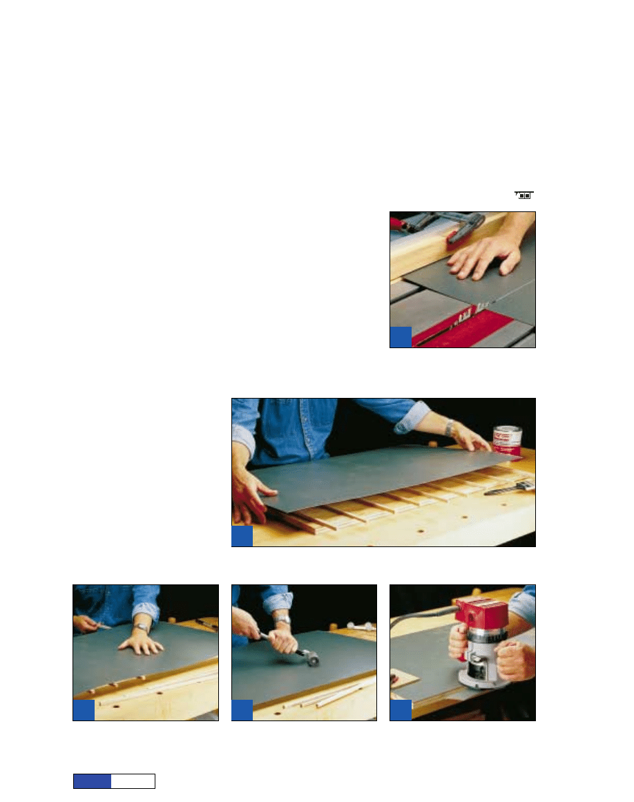
The first hurdle you’ll encounter
with decorative laminate is cutting
the material to size. For most pro-
jects, you’ll want to cut the piece
oversize and trim it with a router
once it’s glued to the substrate
(the panel you use as a gluing
base). I like to leave the laminate
at least 1" oversize along each
edge to give me a comfortable
margin for trimming.
You can cut the rough laminate
blank freehand with a router, as
long as you provide support to
keep the laminate flat
(Figure 1).
The table saw also works fine, but
you’ll need a kerfed wood guide to
keep the laminate from sliding
under your rip fence (Figure 2).
Your next challenge will be mak-
ing the stuff stick where you want.
Even though the core of “plastic”
laminate is really layers of kraft
paper (similar to brown shopping
bags, and also made from wood
fiber), conventional gluing meth-
ods don’t work very well. That’s
because the kraft paper is impreg-
Laying Laminates
Wood always ranks among my
top material choices when it
comes to projects, but I often
add other ingredients — steel or
brass hardware, maybe even
ceramic tile, glass, or some nice
With the rough size marked on the face of
the laminate, support the material near the
line and rout it with a straight bit.
1
1
plans
N O W
page 7
© 1998, August Home Publishing Co.
from
magazine
6
6
A flush-trim router bit, guided by a bearing,
will shear the laminate off along the edges.
Watch for voids in the substrate.
3
3
After you apply contact cement to both the laminate and substrate and let it dry, set clean
spacers onto the substrate. Then position the laminate roughly in place.
Starting at the center of the panel, remove
the spacers and press the laminate down.
The contact cement will bond instantly.
Laminates slide under most fences, so if
you cut the material on the table saw, use a
kerfed wood fence to guide the edge.
5
5
A J-roller helps ensure a strong cement
bond. A double-wheel roller (in background)
can do the edges after trimming.
nated with phenolic plastic resin.
Large furniture and cabinet shops
with full-sheet presses can use
ordinary white or yellow glue, but
for the rest of us, contact cement
works best.
Glue-up: One Shot
You’ll find contact cements with
either solvent-based or water-
borne formulas, and application
methods include brushing, rolling,
and spraying. On really porous
materials you may need two coats
to provide adequate coverage.
The best substrates are engi-
neered wood panels, such as parti-
cleboard, plywood, or medium-
density fiberboard (MDF), that
don’t move as much as solid wood.
Apply the adhesive to both sur-
faces to be joined, but don’t put
them together right away. Allow
the cement time to air-dry (the
sheen will change from glossy to
matte) and to develop a slight tack.
Don’t be fooled by the weak grab
on your finger, though — contact
cement is designed to cling tena-
ciously to itself, bonding instantly
when the two coated surfaces
make contact (hence the name).
You don’t need clamps, but you
have to get it right the first time.
After the cement has set up on
both the laminate and the panel,
you can put the pieces together. I
use thin wood strips as spacers to
hold the material apart until I posi-
tion the laminate (Figure 3).
(Venetian blind slats and wood
dowels are alternatives.)
Once the positioning is correct,
remove the center spacers and
press the laminate down, working
toward each end and removing the
spacers as you go (Figure 4). To
ensure a good bond, I also use
light hammer blows on a wood
block, or pressure from a J-roller,
to seat the laminate completely
(Figure 5). Be careful not to crack
the overhanging laminate at the
edges — you want a clean trim.
Trimming and Edging
With most laminated panels, you’ll
want to trim the excess laminate
flush with the edges of the sub-
strate. A bearing-guided flush-trim
router bit is the surest way to get a
clean edge (Figure 6). The bit’s
carbide flutes shear the laminate
from the edge so there’s none of
the tearout common with sawing
through the face.
There’s another technique I use
when I don’t have a flush-trim bit
handy. I bond an oversize laminate
blank to an oversize substrate,
then cut the panel to size on the
table saw (always with the lami-
nate side up to avoid chipping).
High pressure laminates offer a
durable and easy-to-clean surface
for a lot of projects, not to mention
a wild variety of colors and tex-
tures. They’re easy to apply, and
you can opt for different edge
treatments, including wood mold-
ing that matches your project.
2
2
4
4
plans
N O W
page 8
© 1998, August Home Publishing Co.
Wyszukiwarka
Podobne podstrony:
Router table plans
CNC ROUTER PLANS 5
CNC ROUTER PLANS 4
2 Woodworking Plans Standing Router Table
Router Table Fence Plans
CNC ROUTER PLANS 2
CNC ROUTER PLANS 1
CNC ROUTER PLANS 3
akademia cisco ccna semestr 2 podstawowe wiadomosci o routerach i routingu
6 4 1 2 Packet Tracer Configure Initial Router Settings Instructions
Aktualizacja routera
Przetaktowywanie zegara CPU platformy RouterBoard z serii 500
Konfiguracja routerow CISCO podstawy
MikroTik jako router bezprzewodowy(1)
cennik modemow i routera w ofercie Internetu CP ST 13 06 2011
podsieci i konfiguracja routera
Router, technik informatyk, soisk utk
lynksys router konfiguracja
2004 10 024 033 BEZPRZEWODOWE ROUTERY SIECIOWE
więcej podobnych podstron