
VEHICLE SPEED CONTROL SYSTEM
CONTENTS
page
page
GENERAL INFORMATION
INTRODUCTION . . . . . . . . . . . . . . . . . . . . . . . . . 1
DESCRIPTION AND OPERATION
POWERTRAIN CONTROL MODULE (PCM) . . . . 2
SERVO CABLE . . . . . . . . . . . . . . . . . . . . . . . . . . 2
SPEED CONTROL SERVO . . . . . . . . . . . . . . . . . . 1
SPEED CONTROL SWITCHES . . . . . . . . . . . . . . 1
STOP LAMP SWITCH . . . . . . . . . . . . . . . . . . . . . 1
VACUUM RESERVOIR . . . . . . . . . . . . . . . . . . . . 2
VEHICLE SPEED SENSOR . . . . . . . . . . . . . . . . . 2
DIAGNOSIS AND TESTING
ON-BOARD DIAGNOSTICS TEST . . . . . . . . . . . . 2
POWERTRAIN CONTROL MODULE (PCM) . . . . 7
ROAD TEST . . . . . . . . . . . . . . . . . . . . . . . . . . . . 2
SPEED CONTROL ELECTRICAL TEST . . . . . . . . 6
REMOVAL AND INSTALLATION
POWERTRAIN CONTROL MODULE . . . . . . . . . . 9
SERVO CABLE . . . . . . . . . . . . . . . . . . . . . . . . . . 8
SPEED CONTROL SERVO . . . . . . . . . . . . . . . . . . 7
SPEED CONTROL SWITCHES . . . . . . . . . . . . . . 8
STOP LAMP SWITCH . . . . . . . . . . . . . . . . . . . . . 8
VACUUM RESERVOIR . . . . . . . . . . . . . . . . . . . . 9
VEHICLE SPEED SENSOR . . . . . . . . . . . . . . . . . 9
SPECIFICATIONS
TORQUE . . . . . . . . . . . . . . . . . . . . . . . . . . . . . . . 9
GENERAL INFORMATION
INTRODUCTION
The vehicle speed control system is electronically
controlled and vacuum operated. The system is
designed to operate between approximately 35 and
85 mph (56 and 137 km/h). Following are general
descriptions of the major components in the speed
control system. Refer to Group 8W, Wiring Diagrams
for complete circuit descriptions and wiring dia-
grams.
DESCRIPTION AND OPERATION
SPEED CONTROL SERVO
The speed control servo is located in the engine
compartment, mounted to a bracket on the right
inner fender. The servo unit consists of a solenoid
valve body, a vacuum servo and the mounting
bracket. The PCM controls the solenoid valve body.
The solenoid valve body controls the application and
release of vacuum to the diaphragm of the vacuum
servo. The servo unit cannot be repaired and is ser-
viced only as a complete assembly.
SPEED CONTROL SWITCHES
Two separate speed control switch modules are
mounted on the steering wheel to the left and right
side of the driver’s airbag module. Within the two
switch modules, five momentary contact switches,
supporting seven different speed control functions
are used. The outputs from these switches are fil-
tered into one input. The Powertrain Control Module
(PCM) determines which output has been applied
through resistive multiplexing. The input circuit
voltage is measured by the PCM to determine which
switch function has been selected.
A speed control indicator lamp, located on the
instrument panel cluster is energized by the PCM via
the CCD Bus. This occurs when speed control system
power has been turned ON, and the engine is run-
ning.
The two switch modules are labeled: ON/OFF, SET,
RESUME/ACCEL, CANCEL and COAST. Refer to
the owner’s manual for more information on speed
control switch functions and setting procedures. The
individual switches cannot be repaired. If one indi-
vidual switch fails, the switch module must be
replaced.
STOP LAMP SWITCH
Vehicles equipped with the speed control option use
a dual function stop lamp switch. The switch is
mounted in the same location as the conventional
stop lamp switch, on the brake pedal mounting
bracket under the instrument panel. The PCM mon-
itors the state of the dual function stop lamp switch.
Refer to Group 5, Brakes for more information on
stop lamp switch service and adjustment procedures.
ZJ
VEHICLE SPEED CONTROL SYSTEM
8H - 1

SERVO CABLE
The speed control servo cable is connected between
the speed control vacuum servo diaphragm and the
throttle body control linkage. This cable causes the
throttle control linkage to open or close the throttle
valve in response to movement of the vacuum servo
diaphragm.
POWERTRAIN CONTROL MODULE (PCM)
The speed control electronic control circuitry is
integrated
into
the
Powertrain
Control
Module
(PCM). The PCM is located in the engine compart-
ment behind the coolant recovery tank. The PCM
speed
control
functions
are
monitored
by
the
On-Board Diagnostics (OBD). All OBD-sensed sys-
tems are monitored by the PCM. Each monitored cir-
cuit is assigned a Diagnostic Trouble Code (DTC).
The PCM will store a DTC in electronic memory for
certain failures it detects. See On-Board Diagnostic
Tests in this group for more information. The PCM
cannot be repaired and must be replaced if faulty.
VACUUM RESERVOIR
The vacuum reservoir is mounted below the bat-
tery tray. The reservoir contains a one-way check
valve to trap engine vacuum in the reservoir. When
engine vacuum drops, as in climbing a grade while
driving, the reservoir supplies the vacuum needed to
maintain proper speed control operation. The vacuum
reservoir cannot be repaired and must be replaced if
faulty.
VEHICLE SPEED SENSOR
The Vehicle Speed Sensor (VSS) is a pulse genera-
tor mounted to an adapter near the transmission out-
put shaft. The sensor is driven through the adapter
by a speedometer pinion gear. The VSS pulse signal
is monitored by the PCM speed control circuitry to
determine vehicle speed and to maintain speed con-
trol set speed. Refer to the appropriate Powertrain
Diagnostic Procedures manual for diagnosis and test-
ing of this component. Refer to Group 14, Fuel Sys-
tem for removal/installation procedures.
DIAGNOSIS AND TESTING
ROAD TEST
Perform a vehicle road test to verify reports of
speed control system malfunction. The road test
should include attention to the speedometer.
The cause of any speedometer problems should be
corrected before proceeding. Refer to Group 8E,
Instrument Panel and Gauges for speedometer diag-
nosis.
If a road test verifies a system problem and the
speedometer operates properly, check for:
• A misadjusted brake (stop) lamp switch. This
could also cause an intermittent problem.
• Loose or corroded electrical connections at the
servo. Corrosion should be removed from electrical
terminals and a light coating of Mopar MultiPurpose
Grease, or equivalent, applied.
• Loose or leaking vacuum hoses or connections.
• Secure attachment of both ends of the speed con-
trol servo cable.
• Smooth operation of throttle linkage and throttle
body air valve.
CAUTION:
When test probing for voltage or conti-
nuity at electrical connectors, care must be taken
not to damage connector, terminals or seals. If
these components are damaged, intermittent or
complete system failure may occur.
ON-BOARD DIAGNOSTICS TEST
The Powertrain Control Module (PCM) monitors
critical input and output circuits of the speed control
system making sure they are operational. A Diagnos-
tic Trouble Code (DTC) is assigned to each input and
output circuit monitored by the On-Board Diagnostic
(OBD) system. Some circuits are checked continu-
ously and some are checked only under certain con-
ditions.
If the OBD system senses that a monitored circuit
is bad, it will put a DTC into electronic memory. The
DTC will stay in electronic memory as long as the
circuit continues to be bad. The PCM is programmed
to clear the memory after 50 engine starts if the
problem does not occur again.
DIAGNOSTIC TROUBLE CODES
Diagnostic Trouble Codes (DTC’s) are used to help
identify a faulty circuit. A DTC does not identify
which component in a circuit is bad. Thus, a DTC
should be treated as a symptom, not as the cause for
the problem. In some cases, because of the design of
the diagnostic test procedure, a DTC can be the rea-
son for another DTC to be set. Therefore, it is impor-
tant that the test procedures be followed in sequence
to understand what caused a DTC to be set.
A DTC can be displayed in three different ways:
• a two-digit number flashed on the Malfunction
Indicator (Check Engine) Lamp
• a two-digit number displayed on the vehicle
odometer
• a description of the DTC can be read using the
DRB scan tool
Refer to Group 25, Emission Control System for
more DTC information.
Refer to the following Speed Control Diagnostic
Trouble Code chart for DTC’s which apply to the
speed control system. Refer to the appropriate Pow-
8H - 2
VEHICLE SPEED CONTROL SYSTEM
ZJ
DESCRIPTION AND OPERATION (Continued)
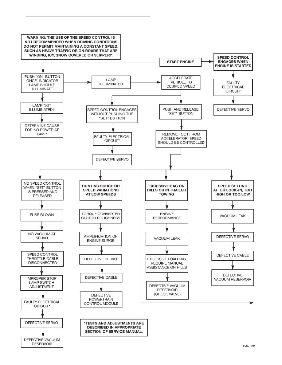
DIAGNOSIS CHART 1
ZJ
VEHICLE SPEED CONTROL SYSTEM
8H - 3
DIAGNOSIS AND TESTING (Continued)
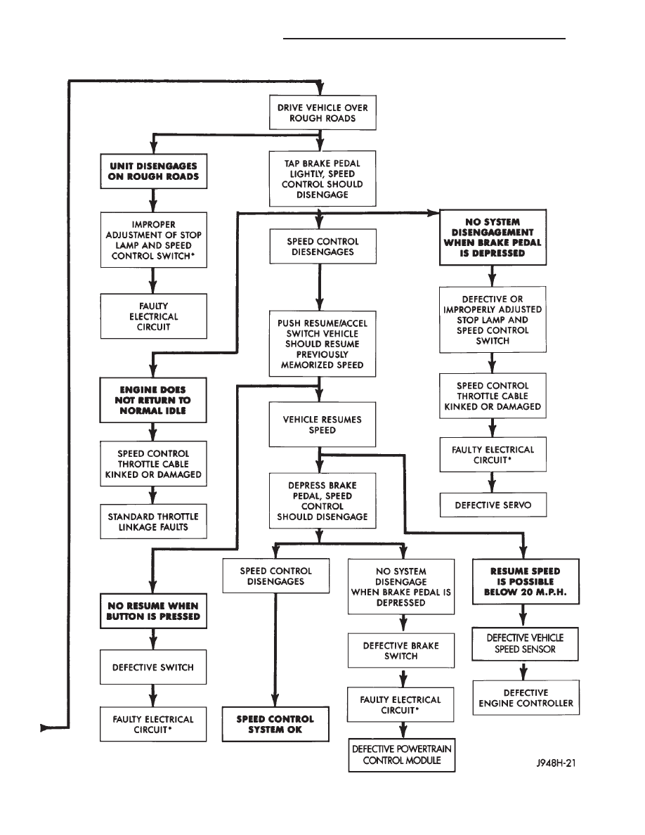
DIAGNOSIS CHART 2
8H - 4
VEHICLE SPEED CONTROL SYSTEM
ZJ
DIAGNOSIS AND TESTING (Continued)

ertrain Diagnostic Procedures manual to diagnose an
on-board diagnostic system trouble code.
RETRIEVING DIAGNOSTIC TROUBLE CODES
To start this function, cycle the ignition switch ON-
OFF-ON-OFF-ON within 5 seconds. This will cause
any DTC stored in the PCM memory to be displayed.
The instrument panel mounted malfunction indicator
(Check Engine) lamp will display a DTC by flashing
on and off. There is a short pause between flashes
and a longer pause between digits. All DTC’s dis-
played are two-digit numbers, with an approximate
four-second pause between codes.
An example of a DTC is as follows:
(1) Lamp on for 2 seconds, then turns off.
(2) Lamp flashes 1 time pauses and then flashes 5
times.
(3) Lamp pauses for 4 seconds, flashes 3 times,
pauses, then flashes 4 times.
While the lamp is flashing, a two-digit number will
also be displayed on the vehicle odometer.
The three DTC’s are 15, 34 and 77. Any number of
DTC’s can be displayed, as long as they are in mem-
ory. The lamp will flash until all stored DTC’s are
displayed. A DTC code number 55 signifies the end of
tests.
If a DTC number 15, 34 or 77 is observed, refer to
the appropriate Powertrain Diagnostic Procedures
manual. Correct any problems found in your diagno-
sis, then recheck for a DTC after corrections are com-
pleted. Use the DRB scan tool to erase a DTC after
repair.
SPEED CONTROL DIAGNOSTIC TROUBLE CODES
Diagnostic
Trouble Code
DRB Scan Tool Display
Description of Diagnostic Trouble Code
15**
No Vehicle Speed Sensor Signal
No vehicle distance (speed) sensor signal
detected during road load conditions.
34*
S/C Switch High or Low
MUX S/C Switch High or Low
77*
S/C Pow. Ckt.
Speed Control Power Circuit Problem
55*
N/A
Completion of fault code display on Check
Engine Lamp.
* Check Engine Lamp will not illuminate at all times if this Diagnostic Trouble Code was recorded. Cycle ignition key
as described in manual and observe code flashed by Check Engine Lamp.
** Check Engine Lamp will illuminate during engine operation if this Diagnostic Trouble Code was recorded.
ZJ
VEHICLE SPEED CONTROL SYSTEM
8H - 5
DIAGNOSIS AND TESTING (Continued)
SPEED CONTROL ELECTRICAL TEST
Two different test methods may be used to check
the electronic speed control system. One involves
using the DRB scan tool. If this test method is
desired, refer to the appropriate Powertrain Diagnos-
tic Procedures service manual.
The other test method will involve the use of a
volt/ohm meter. The volt/ohm meter method is
described within the tests on the following pages.
Refer to Group 8W, Wiring Diagrams for speed con-
trol electrical schematics and connector location.
CAUTION:
When test probing for voltage or conti-
nuity at electrical connectors, care must be taken
not to damage connector, terminals or seals. If
these components are damaged, intermittent or
complete system failure may occur.
When electrical connections are removed, corrosion
should be removed from electrical terminals and a
light coating of Mopar Multi-Purpose Grease, or
equivalent, should be applied.
Inspect connectors for damaged terminals. A poor
electrical connection can cause a complete or inter-
mittent malfunction. For this reason, a poor connec-
tion
may
be
misdiagnosed
as
a
component
malfunction.
VEHICLE SPEED SENSOR
For diagnosis and testing of the speed sensor, refer
to the appropriate Powertrain Diagnostic Procedures
service manual.
SPEED CONTROL SWITCHES
For complete speed control system diagnosis, refer
to the appropriate Powertrain Diagnostic Procedures
manual. To test each of the speed control switches
only, refer to the following:
WARNING:
BEFORE ATTEMPTING TO DIAGNOSE,
REMOVE OR INSTALL ANY AIRBAG SYSTEM OR
RELATED STEERING WHEEL AND STEERING COL-
UMN COMPONENTS, YOU MUST FIRST DISCON-
NECT AND ISOLATE THE BATTERY NEGATIVE
(GROUND) CABLE. WAIT 2 MINUTES FOR SYSTEM
CAPACITOR TO DISCHARGE BEFORE FURTHER
SYSTEM SERVICE. FAILURE TO DO SO COULD
RESULT IN ACCIDENTAL AIRBAG DEPLOYMENT
AND POSSIBLE PERSONAL INJURY.
(1) Disconnect negative battery cable. Wait 2 min-
utes for airbag system capacitor to discharge.
(2) Remove the two speed control switch modules
from steering wheel. Refer to the removal/installation
section for procedures.
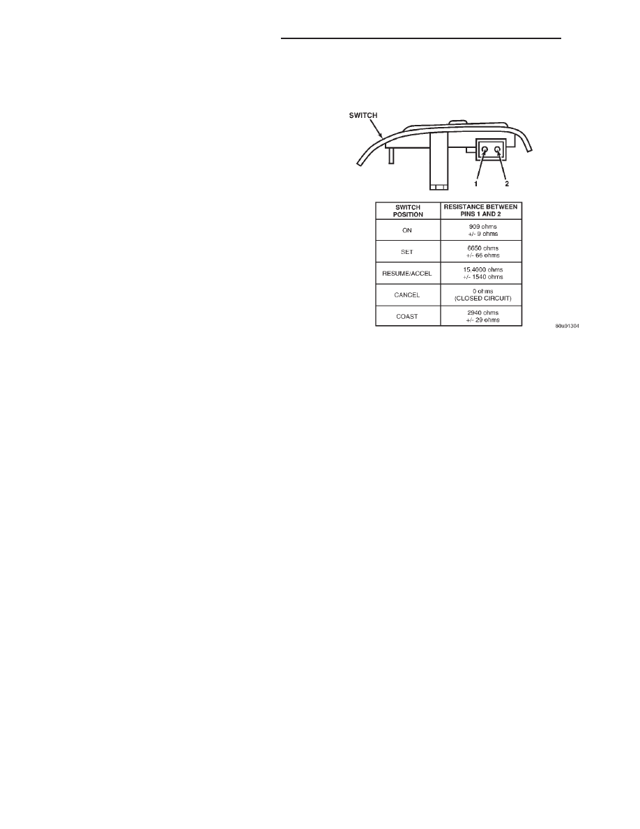
(3) Check continuity of each individual speed con-
trol switch module as shown in chart (Fig. 1). If OK,
reinstall switch. If not OK, replace switch module
assembly.
STOP LAMP SWITCH
For continuity checks and switch adjustment, refer
to Group 5, Brakes.
VACUUM SUPPLY TEST
(1) Disconnect vacuum hose at speed control servo
and install a vacuum gauge into the disconnected
hose.
(2) Start engine and observe gauge at idle. Vac-
uum gauge should read at least ten inches of mer-
cury.
(3) If vacuum is less than ten inches of mercury,
determine source of leak. Check vacuum line to
engine for leaks. Also check actual engine intake
manifold vacuum. If manifold vacuum does not meet
this requirement, check for poor engine performance
and repair as necessary.
(4) If vacuum line to engine is not leaking, check
for leak at reservoir. Disconnect vacuum line at res-
ervoir and connect a hand-operated vacuum pump to
reservoir fitting. Reservoir vacuum should not bleed
off. If vacuum is being lost, replace reservoir.
SPEED CONTROL SERVO
For complete speed control system diagnosis, refer
to the appropriate Powertrain Diagnostic Procedures
manual. To test the speed control servo only, refer to
the following:
The engine must be started and running for the
following voltage tests.
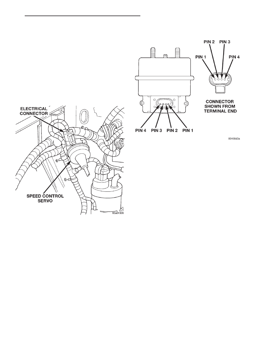
(1) Start engine.
(2) Disconnect 4–way electrical connector at servo
(Fig. 2).
Fig. 1 Speed Control Switch Continuity
8H - 6
VEHICLE SPEED CONTROL SYSTEM
ZJ
DIAGNOSIS AND TESTING (Continued)
(3) Turn speed control switch to ON position.
(4) Check for battery voltage at pin–3 of wiring
harness 4–way connector (Fig. 3). This is the 12 volt
feed from the stoplamp switch. When the brake pedal
is depressed, voltage should not be present at pin–3.
If voltage is not present with brake pedal not
depressed, check for continuity between servo and
stop lamp switch. Also check stop lamp switch
adjustment. Refer to Group 5, Brakes for procedures.
(5) Connect a small gauge jumper wire between
the disconnected servo harness 4–way connector
pin–3, and pin–3 on the servo. Check for battery volt-
age at pins–1, 2 and 4 of the servo. If battery voltage
is not at these pins, replace the servo.
(6) Turn ignition switch to OFF position. Check for
continuity
between
disconnected
servo
harness
4–way connector pin–4 and a good ground. There
should be continuity. If not OK, repair open circuit to
ground as required.
POWERTRAIN CONTROL MODULE (PCM)
For complete PCM diagnosis on the speed control
system, refer to the DRB scan tool and the appropri-
ate Powertrain Diagnostic Procedures manual.
REMOVAL AND INSTALLATION
SPEED CONTROL SERVO
4.0L ENGINES—REMOVAL/INSTALLATION
(1) Disconnect vacuum hose at servo.
(2) Unplug electrical connector at servo.
(3) Remove 2 nuts holding servo cable sleeve.
(4) Pull speed control cable sleeve away from servo
to expose cable retaining clip.
(5) Remove clip attaching cable to servo.
(6) Remove servo from mounting bracket.
(7) Reverse removal procedures to install. Block
throttle to full open position to align hole in cable
connector with hole in servo pin and install retaining
clip. Tighten servo mounting nuts to 8.5 N·m (75 in.
lbs.).
CAUTION:
The cable sleeve must be installed on
the OUTSIDE face of the bracket to avoid possible
binding of the cable.
5.2L ENGINES—REMOVAL/INSTALLATION
(1) Disconnect vacuum hose at servo.
(2) Unplug electrical connector at servo.
(3) Remove 2 nuts from servo mounting bracket.
(4) Remove and discard push nuts on servo studs.
(5) Remove servo from mounting bracket.
(6) Pull speed control cable sleeve away from servo
to expose cable retaining clip.
(7) Remove clip attaching cable to servo.
(8) Reverse removal procedures to install. Block
throttle to full open position to align hole in cable
connector with hole in servo pin and install retaining
clip. Install new push nuts on servo studs. Tighten
servo mounting nuts to 8.5 N·m (75 in. lbs.).
CAUTION:
The cable sleeve must be installed
BETWEEN the servo and bracket to avoid possible
binding of the cable.
Fig. 2 Servo Electrical Connector Location
Fig. 3 Servo 4–Way Harness Connector
ZJ
VEHICLE SPEED CONTROL SYSTEM
8H - 7
DIAGNOSIS AND TESTING (Continued)
SPEED CONTROL SWITCHES
REMOVAL/INSTALLATION
WARNING:
BEFORE BEGINNING ANY AIRBAG
SYSTEM COMPONENT REMOVAL OR INSTALLA-
TION, REMOVE AND ISOLATE THE NEGATIVE (-)
CABLE FROM THE BATTERY. THIS IS THE ONLY
SURE WAY TO DISABLE THE AIRBAG SYSTEM.
THEN WAIT TWO MINUTES FOR SYSTEM CAPACI-
TOR TO DISCHARGE BEFORE FURTHER SYSTEM
SERVICE. FAILURE TO DO THIS COULD RESULT IN
ACCIDENTAL AIRBAG DEPLOYMENT AND POSSI-
BLE INJURY.
(1) Disconnect and isolate negative battery cable.
(2) Remove airbag module. Refer to Group 8M for
procedures.
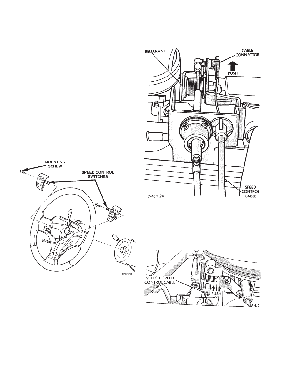
(3) Remove
switch-to-steering
wheel
mounting
screw (Fig. 4).
(4) Remove switch.
(5) Reverse removal procedures to install.
STOP LAMP SWITCH
Refer to Group 5, Brakes for removal/installation
and adjustment procedures.
SERVO CABLE
REMOVAL/INSTALLATION
(1) 4.0L
Engine:
Using
finger
pressure
only,
remove speed control cable connector at throttle body
bellcrank pin by pushing connector off the bellcrank
towards the drivers side of vehicle (Fig. 5). DO NOT
try to pull connector off perpendicular to the
bellcrank pin. Connector will be broken.
(2) 5.2L
Engine:
Using
finger
pressure
only,
remove speed control cable connector at throttle body
bellcrank by pushing connector rearward off the
bellcrank pin (Fig. 6). DO NOT try to pull connec-
tor off perpendicular to the bellcrank pin. Con-
nector will be broken.
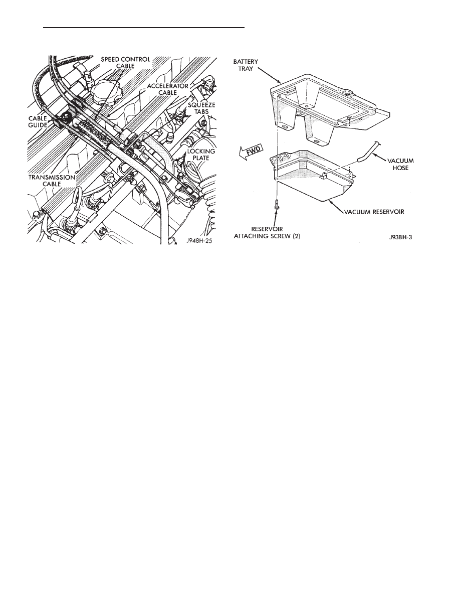
(3) 4.0L Engine: Remove cable from cable guide at
top of valve cover (Fig. 7).
(4) Squeeze 2 tabs on sides of speed control cable
at throttle body mounting bracket (locking plate) and
push out of bracket.
Fig. 4 Speed Control Switches
Fig. 5 Cable at Bell Crank—4.0L Engine
Fig. 6 Cable at Bell Crank—5.2L V-8 Engine
8H - 8
VEHICLE SPEED CONTROL SYSTEM
ZJ
REMOVAL AND INSTALLATION (Continued)
(5) Remove servo cable from servo. Refer to Speed
Control Servo removal and installation in this group.
(6) Reverse removal procedures to install.
POWERTRAIN CONTROL MODULE
For Removal/Installation refer to Group 14, Fuel
Injection System.
VACUUM RESERVOIR
REMOVAL/INSTALLATION
(1) Disconnect both battery cables, negative cable
first.
(2) Remove battery holddowns.
(3) Remove battery from battery tray.
(4) Remove 5 bolts securing battery tray.
(5) Pull up battery tray and remove vacuum line
from reservoir (Fig. 8).
(6) Remove 2 screws holding reservoir to battery
tray.
(7) Reverse removal procedures to install. Tighten
hardware as follows:
• vacuum reservoir mounting bolts to 3 N·m (30
in. lbs.)
• battery tray mounting bolts to 10 N·m (90 in.
lbs.)
• battery holddown bolts to 10 N·m (90 in. lbs.)
• battery cable clamp bolts to 8.5 N·m (75 in. lbs.).
VEHICLE SPEED SENSOR
For Removal/Installation of the Vehicle Speed Sen-
sor refer to Group 21, Transaxle..
SPECIFICATIONS
TORQUE
Description
Torque
Servo Mounting Bracket-to-Servo
Nuts. . . . . . . . . . . . . . . . . . . . .8.5 N·m (75 in. lbs.)
Servo Mounting Bracket-to-Body
Nuts . . . . . . . . . . . . . . . . . . . . . .5 N·m (47 in. lbs.)
Switch Module Mounting
Screws . . . . . . . . . . . . . . . . . . .1.5 N·m (15 in. lbs.)
Vacuum Reservoir Mounting
Bolts . . . . . . . . . . . . . . . . . . . . . .4 N·m (35 in. lbs.)
Fig. 7 Cable Guide/Locking Plate—4.0L Engine
Fig. 8 Vacuum Reservoir
ZJ
VEHICLE SPEED CONTROL SYSTEM
8H - 9
REMOVAL AND INSTALLATION (Continued)

Document Outline
- VEHICLE SPEED CONTROL SYSTEM
- GENERAL INFORMATION
- DESCRIPTION AND OPERATION
- DIAGNOSIS AND TESTING
- REMOVAL AND INSTALLATION
- SPECIFICATIONS
Wyszukiwarka
Podobne podstrony:
93ZJ Secc 8H Vehicle Speed Control System
96ZJ 8Q VEHICLE THEFT SECURITY SYSTEMS
80 Vehicle Control System
80 Vehicle Control System
96ZJ 25 EMISSION CONTROL SYSTEMS
80 Vehicle Control System
80 Vehicle Control System
Control System Toolbox
10 Emission control system
07 emission control system
10 Engine Control System
ENGINE CONTROL SYSTEM
530 Speed controllers 1202 EN
10 Engine Control System
Core Wall Survey Control System for High Rise Buildings
Air Control System
Microprocessor Control System for PWM IGBT Inverter Feeding Three Phase Induction Motor
Control Systems Simulation using Matlab and Simulink
opis Control System XControl XC XV
więcej podobnych podstron