
1
Electric Automatic
Temperature Regulating Valve
(PID Control)
NT2.120.001JS
INSTRUCTION MANUAL
Nanjing TP Thermal Engineering CO.,LTD.

2
Table of Contents
Chapter1 General Specification
Chapter2 Structure and Function
Instrumentation and Wiring
Operation Mechanism
Main Technical Parameters
Chapter3 Specification of Main Devices
Valve Body
Sensor
Electric Temperature Controller
Notice of Installing
Chapter4 System Operation
Starting
Method of Change Set Temperature
Operating process
Chapter5 Maintenance
Chapter6 Trouble Shooting
Chapter1 General Specification
Electric Automatic Temperature Regulating Valve (briefly called as Elect. Valve) are mainly used for
temperature auto-control of lubricant or fresh water in cooling system of power units in marine and other kinds
of ships, and also widely used in diesel engine, air compressors, lubricating equipment, generator sets etc. Our
products have the features of high accuracy, setting temperature easily, having alarm function. It is easy to be
centralized controlled by computer.
Chapter2 Structure and Function
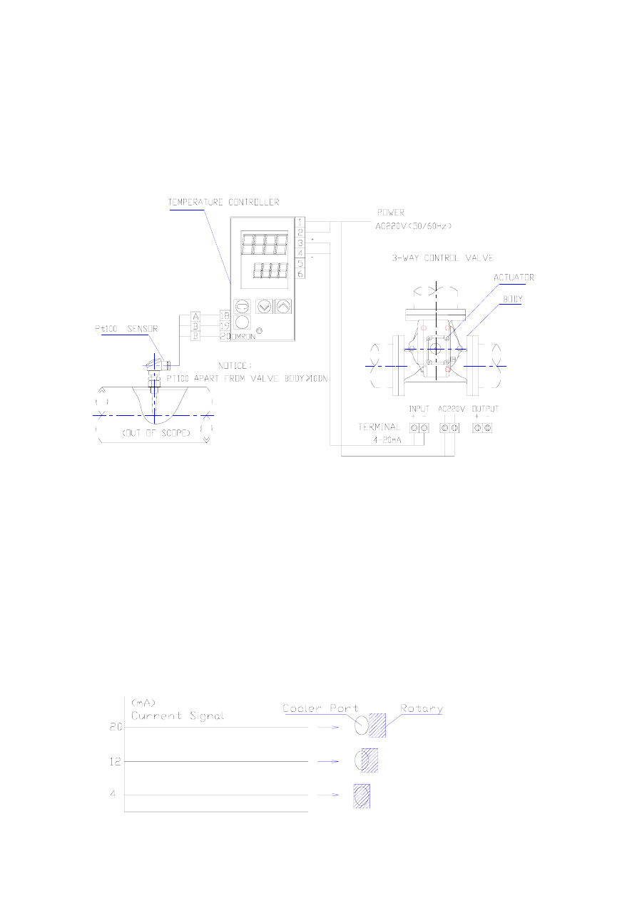
1. Instrumentation and Electrical Wiring Diagram
2. Operation Mechanism
The sensor (Platinum Resistance Thermometer) installed to the particular position for the desired control
in the piping detected the temperature of applied fluid to generate the resistance the which corresponds to each
temperature controller. The resistance value thus reaching the temperature controller causes the output current
4 mA to 20 mA to be delivered to the electrical motor. The signal current is then input to the positioner at the
main body driving section.
The rotor of the driving section is rotated in proportion to the signal currents, so that the flow rates on
both side B and side C are changed by the aperture adjustment at the said two sides made every moment in
accordance with the temperature variation.
As for the control by the temperature controller, advanced PID control with two degrees of freedom is
employed. The controller needs the shortest rise time, does not allow overshooting, and resumes a stabilized
condition very fast in the event of disturbance.
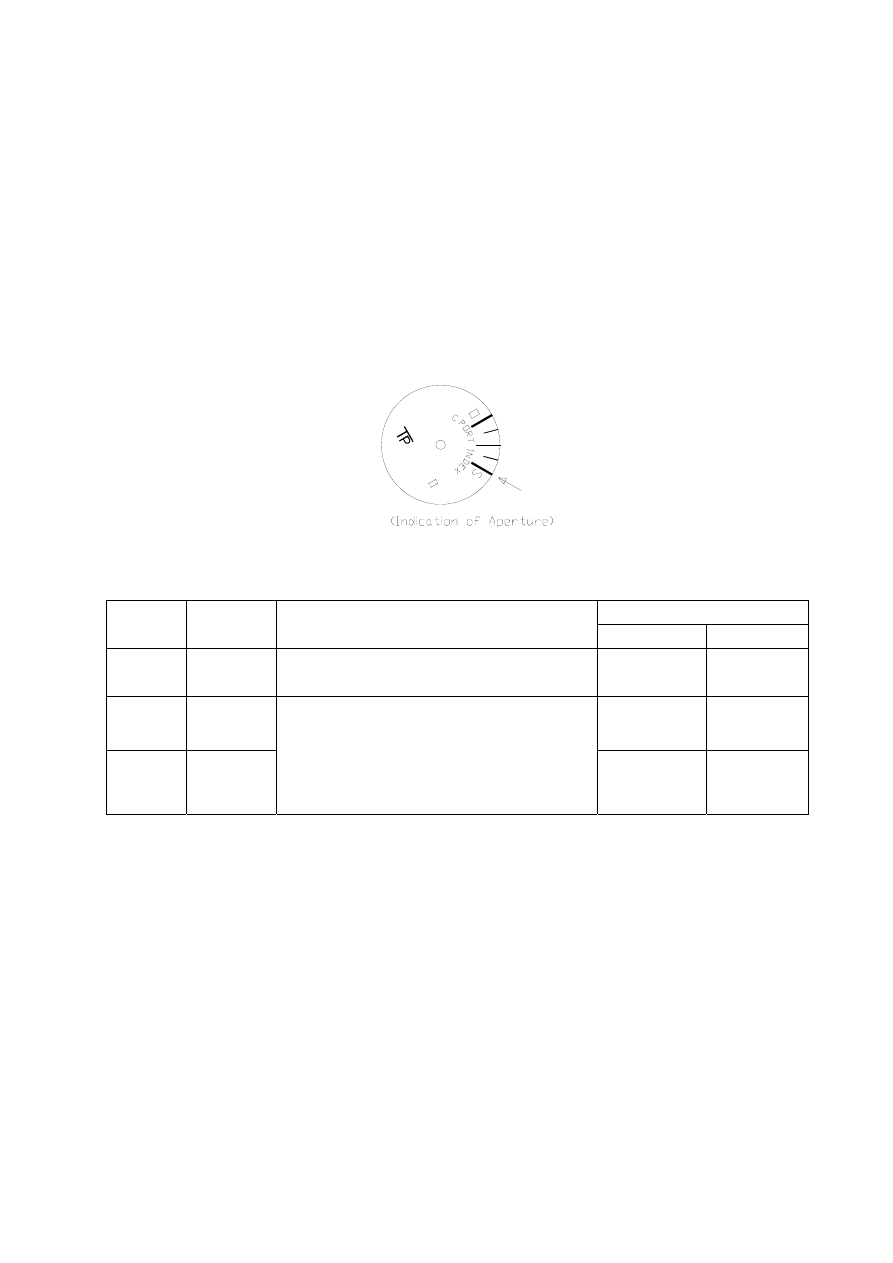
(*)Relationship Between Signal Currents and Aperture(In Case of Reverse Action)
3
3.
Main Technical Parameters
3.1 Working medium: Fresh water, Lubricant, Seawater;
3.2 The insensitivity of the Elect. Valve is not than 1℃;
3.3 The relative leakage of the Elect. valve for rotating type isn’t more than 3%;
3.4
The max working pressure of the Elect. valve is 1.0Mpa;
3.5 The Elect. Valve can be controlled manually;
3.6 The Elect. Valve works under the conditions:
a. Ambient Temperature:0~+55℃;
b. Ambient Humidity: 95%±3%;
c. Fog of oil and salt;
d. The rake and swing of each direction 22.5°,cycle 10s;
e. Shaking:frequency 2~13.2Hz,range 1mm;frequency 13.2~100Hz,acceleration 1G。
Chapter3 Specification of Main Devices
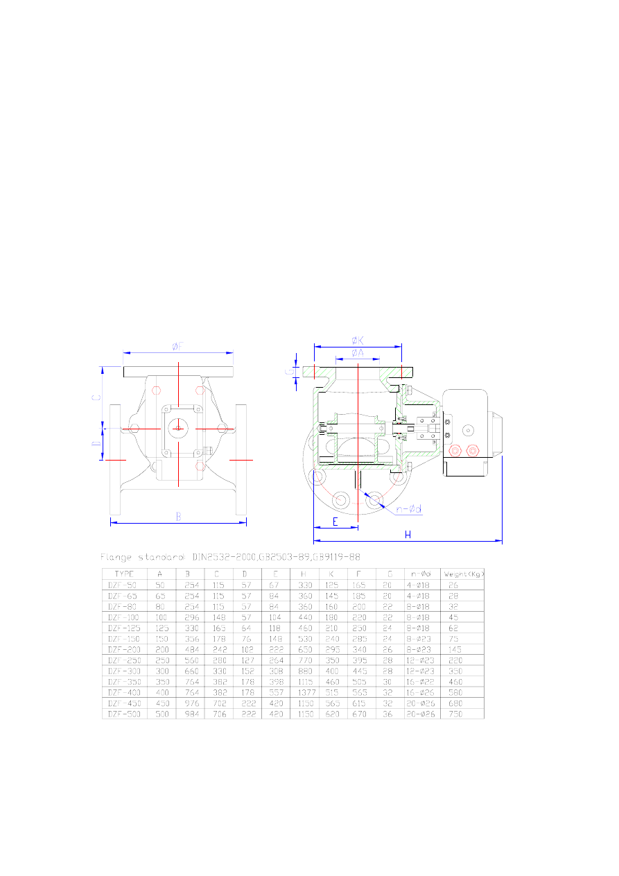
1. Valve Body
1.1 Outline, Installation and Main Sizes
4
1.2 The rated pressure of body is 1.0MPa,the pressure of test is 1.5MPa(5min)。
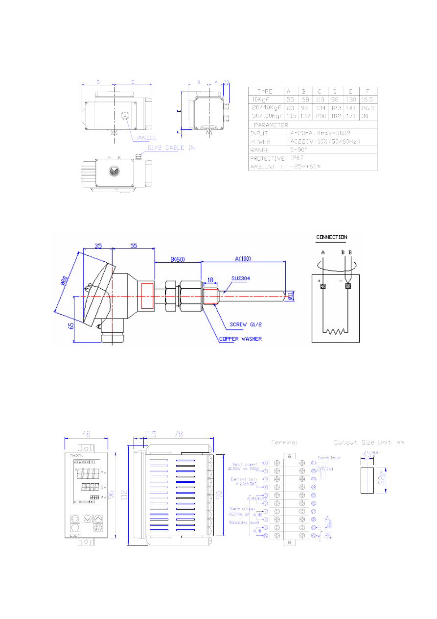
1.3 The main technical parameter of the electronic actuator:
2. Sensor
2.1 Sensor is imported from Japan (PT100), with stainless steel socket. It’s outline is:
2.2 Technical parameter:
a. Range of temperature:0~+200℃;
b. Class of accuracy:B, △t=±(0.3+0.005|t|) ;
c. Class of protective: IP65;
3. Electric Temperature Controller
5

6
※NOTICE OF INSTALLING:
1. For installation in pipeline, over-force of pipe should be avoided in case the valve deformed.
2. The situation of valve is benefit to operate and service.
3. The pipe that the valve wants to be fixed must be thoroughly cleaned, and have no any foreign matter.
4. The electrical wire is must correct fully, otherwise maybe cause another component damaged.
Chapter4 System Operating
1. Starting
※Before turning on power, correct wiring and power type must be confirmed!
After turning on power, the temperature controller displays the previous value of temperature (PV) and
the setting value (SV).
NOTICE: According to “the temperature controller setup table (apex 1)”, the basic parameters of
temperature controller have been setup and locked before delivery. User do not setup it again, otherwise it
could cause the system to be out of order.
2. Method of Change Set Temperature
If the setting value of temperature needs changing, only push “↑” or “↓” key, OK!
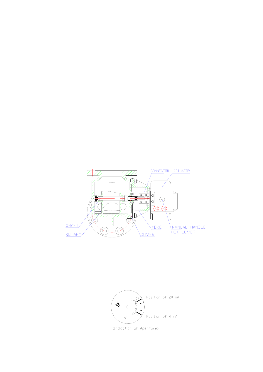
3. Actuator’s indication of opening degree
It indicates the relation of rotary to port C. “S”is port C closed fully. “O”is port C opened fully. The
middle indication is port C and port B opens half each other.
4. Working process
At beginning, the temperature of liquid is lower. PV<SV, port C is closed fully. Liquid flows from port A
to port B.
With the temperature rising, PV>SV, port C opens a little slowly and port B closes a little slowly. Liquid
flows from port A=port (B+C).
At last, PV is approaching SV. The system is stable.
Chapter5 Maintenance
Regular inspection
For keeping stable performance for years it is necessary to regularly inspect the valve system in the following
manner.
(1)Shutting off power ,regularly inspect the valve system using the manual lever(once a month). (The
manual lever must turn lightly with the valve gully open or closed.)
(2)Regularly overhaul the inside of the valve(once a year). In the case of seawater specifications, conduct
overhaul inspection twice a year to check conditions of rust. An O-ring (The bye ton) is used for sealing the
shaft. Change the O-ring when occurs water leakage due to its qualitative deterioration or wearing.(For its size,
see the last page.)
Method to overhaul the side of valves
(1)Seeing the opening degree indication of the electronic actuator, set Ⅰ-type to “S” side and Ⅱ-type to
“O” side . This can be done either by changing set values of the electronic temperature regulator or by
operating the manual lever, shutting off the power for the electronic actuator.
(2)Shut off the power for the electronic actuator and drain off the water inside the valve.
(3)Remove all 4 connecting metal fastening bolts.
(4)Remove yoke fitting bolts(valve side).
(5)Remove the electronic actuator together with yoke.
(6)Remove all cover fastening bolts.
(7)Take out the inner assembly together with the upper cover. Thus, disassembling the inside is completed.
So, follow the procedures given the below.
(8)Check if there is any rust or foreign matter inside the main unit. If any, take it out.
(9)Check if there is any foreign matter or abnormality on the upper cover and inner assembly.
(10)Check if there is any other abnormality(e.g. bending of shaft defective bearings, etc.).
(11)Insert the inner assembly together with the upper cover into the main unit.(Be sure to insert the cover
seal together).
(12)Fit cover fastening bolts(excluding bolts for the yoke).
(13)Install the electronic actuator and yoke and fasten their bolts.
(14)Turning the shaft, adjust the setting mark “.” of the shaft setting mark “.” of the electronic actuator.
(15)Fasten the connecting metal with 4 bolts.
(16)Turn on the power switch and the valve will function again with opening degrees to automatically
respond to signals and regulate the temperature accordingly.
The way of operating an drive part lever
When the temperature rises, it I possible to do manual lever operation in the time with power supply
malfunction, others malfunction.
(1)It makes a power supply off.
(2)It puts hexagon wrench in the manual operation part (the 6 corner hole) of actuator and it operates it.
Because it maintains in the fixed position, turn a lever in opening degrees with the temperature to want to
control.
(3)On the power supply when automatic results when extraordinary cause is removed and when results,
valve opening degrees does a temperature control in opening degrees which followed a signal automatically
about any position by the manual operation.
Chapter 6 Trouble shooting
When the temperature is abnormally high (for the case of reverse function)
(1)Is the electronic temperature controller transmitting control output? If transmitted, it must be less than
20mA. If it stays unchanged at 20mA,it can be said that the electronic temperature controller is out of order
and needs checking. (See the item concerning “Abnormality of the electronic temperature controller” in last
page)
(2)If the electronic temperature controller does not function properly while its control output is normal , it
7
can be considered that it is malfunctioning because of foreign matter, rust, etc. In such a case, follow the
instructions of Chapter 5 (Maintenance and Inspection.)
When it is found that the malfunction is not attributable to foreign matter or rust, it can be considered that
there exits some abnormality in the cooling capacity or the circulating water. So, check both accordingly.
Further, in case of the emergency it is possible to regulate temperature using the manual lever (see
“Method to handle the driving part lever” Chapter 5)
When the temperature is abnormally low (for the case of reverse function)
(1)Is the electronic temperature controller transmitting control output? If transmitted, it must be over than
4mA. If it stays unchanged at 4mA,it can be said that the electronic temperature controller is out of order and
needs checking. (See the item concerning “Abnormality of the electronic temperature controller” in last page)
(2)When the temperature is low while the opening degree indication is “S”, it can be considered that there
exist some other some other causes(in the piping system, etc.) So, check such accordingly.
When it is suspected that there has occurred a failure
Phenomenon: Nothing is indicated while the power switch is turned on.
Output (failure)
Display 1
Cause
Countermeasure
Control signal
Alarm output
5Err
Input
failure
Check the connection wiring of the sensor, and
check the type of the sensor.
no
High Temp.
yes
E111
Memory
failure
no no
HErr HB
failure
Turn off the power switch, and turn on again, if
failure code displays stilly. Thus the electronic
temperature controller needs checking.
If display is correctly, it can be said that
because of the noise, and check it.
no no
Nanjing TP Thermal Engineering CO.,LTD.
Adress:Nanjing Economic & Technological Development Zone No.6-1 Xingwen Road
Tel:025-85803553,85804180
Fax:025-85803776,85804180
P.C.:210038
8
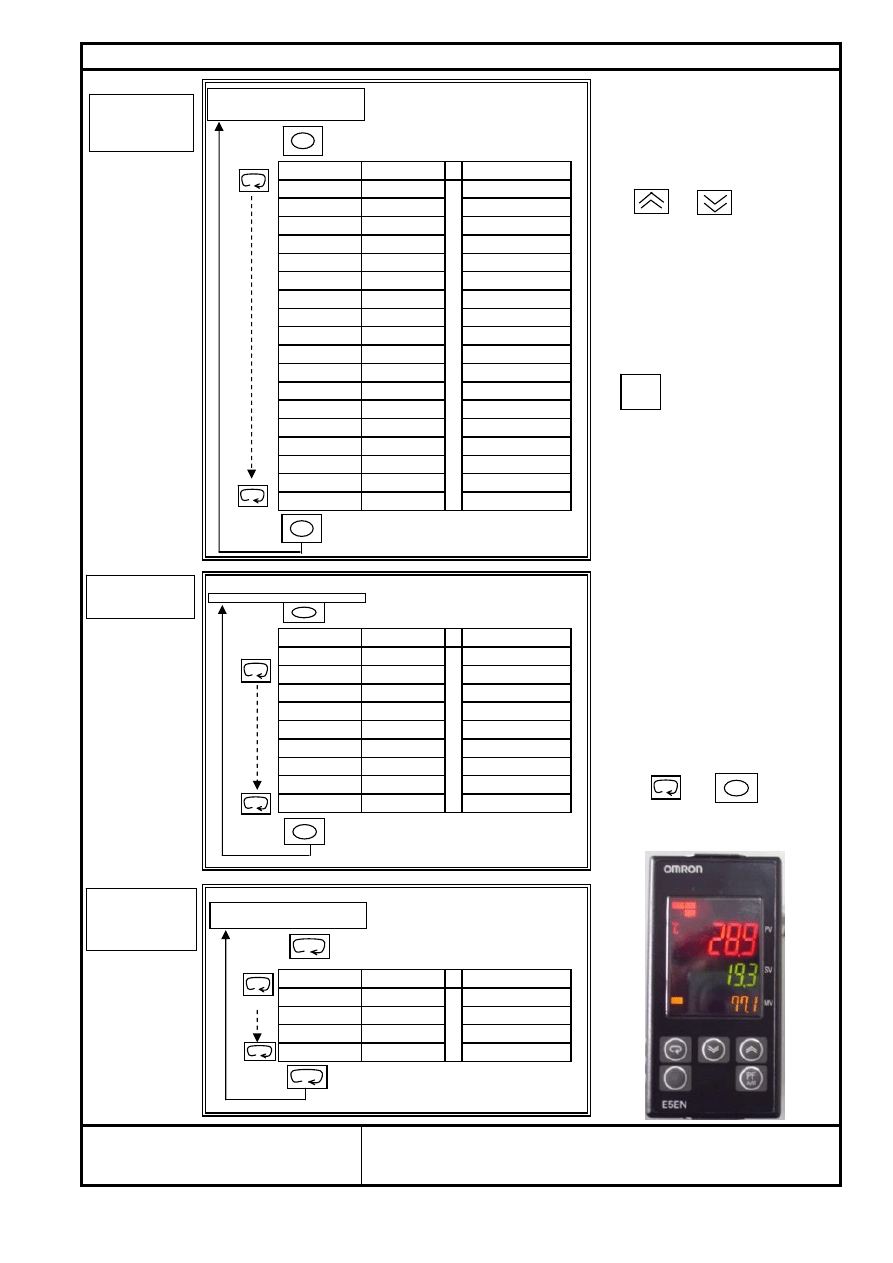
Temp. Controller Initial Setting(before delivery)
Note:
1、Each setting value varied by
display code
setting value
meaning
“upper”“down”key;
IN-t
3
input type
d-U
C
unit ℃/F
SL-H
500
upper limit
SL-L
-199.9
lower limit
2、Display value is setting value,
CNtL
PId
control type
and do not press any key to approval.
S-HC
StNd
standard
St
oFF
self-turning
3、Commissioning is prohibited in
PtRN
oFF
program pattern
the course of the two keys at the same
OREV
oR-d
direct operation
same time, otherwise they will enter
ALt 1
2
alarm 1 type
the state Dead.
ALH1
0.2
alarm 1 hysteresis
ALt 2
2
alarm 2 type
4、 Function key/auto/manual
ALH2
0.2
alarm 2 hysteresis
ALt 3
2
alarm 3 type
key press this function key to operate
ALH3
0.2
alarm 3 hysteresis
the function set with the PF setting .
tR-t
oFF
transfer output type
o1-t
4-20
liner output type
AMoV
0
5、In the initial interface.Regulate
"upper" and "down" key to Change
the temperature setting SV.
6、MV,Shows that the percentage
output.
display code
setting value
meaning
7.(protect level)
L.AdJ
adjustment level
1.OAPT(operation/adjustment): 2
At
oFF
AT cancel
2.ICPT(initial/communication): 2
IN5
0
input shift
3.WTPT(setting change): off
P
15
proportional band
4.PRLP(move to protect level): 0
I 100
integral
time
d
25
derivative time
SPRt
oFF
SP ramp set value
8、Unlock:
OL-H
105
Press and 3 seconds
OL-L
-5
1.OAPT(operation/adjustment): 0
2.ICPT (initial/communication): 0
display code
setting value
meaning
R-5
RUN
run/off
AL-1
5.0
deviation limit
AL-2
5.0
deviation limit
AL-3
5.0
deviation limit
CO.,Ltd
Temp.Controller Type:
E5EN-C3T-N
Nanjing TP Thermal Engineering
Hold down for at least 1 second
Hold down for at least 3 seconds
Press less than 1 second
Press less than 1 second
Press less than 1 second
Press less than 1 second
operation level
Initinal
setting
Adjustment
level
ti
l
l
operation level
Alarm value
setting
PF
A/M
Document Outline
Wyszukiwarka
Podobne podstrony:
08 INSTRUCTION MANUAL TEMPERATURE CONTROL VALVE 12160 3078
DJ F1 S1 Instruction Manual
Electrical Safety Student Manual
Electronic Flight Instruments System, Lotnicze różności
BSA Instruction Manual D14
Instruction Manual
ICOM instruction manual[1]
DJ F1 S1 Instruction Manual
09 INSTRUCTION MANUAL OIL PUMP 12143 3055 E
MALOWANIE LINJI easylineedge instruction manual
Electrolux ER 7326 C Manual
Electrolux ER 9096 B Manual
Instrukcja (manual) wymiany linek hamulca ręcznego (pomocniczego, awaryjnego) fiat punto I (1,1)
Electrolux ERB4010AC Instrukcja
102003BGA Reballing Instruction Manual
Electrolux ERB 4032 Manual
#0449 – Using an Instruction Manual
06 INSTRUCTION MANUAL FUEL OIL FILTER 12153 3188 E
07c John Ashbery The Instruction Manual
więcej podobnych podstron