
Copyright © 1997 Cisco Systems, Inc. All Rights Reserved.
Page 1 of 25
White Paper
Enabling Enterprise Multihoming
with Cisco IOS Network Address
Translation (NAT)
Praveen Akkiraju, Cisco Consulting Engineering
Kevin Delgadillo, Cisco IOS Product Marketing
Yakov Rekhter, Cisco Fellow
Introduction
An enterprise may wish to acquire its Internet connectivity from more than one Internet Service Provider (ISP) for several reasons.
Maintaining connectivity via more than one ISP can be viewed as a way to increase the reliability of Internet connectivity. Such
multiply connected enterprises are referred to as being “multi-homed.” When connectivity through one of the ISPs fails, connectivity
via the other ISP(s) enables the enterprise to preserve its connectivity to the Internet. In addition to providing more reliable
connectivity, maintaining connectivity via more than one ISP also enables the enterprise to distribute load among multiple
connections. For enterprises that span wide geographical areas, this could also enable better (more optimal) routing.
The above considerations, combined with the decreasing prices for the Internet connectivity, motivate more and more
enterprises to become multi-homed. At the same time, the routing overhead that such enterprises impose on the Internet routing
system becomes more and more significant. Scaling the Internet, and being able to support a growing number of such enterprises
demands scalable mechanism(s) to contain this overhead. We assume that an approach where routers in the “default-free” zone of
the Internet would be required to maintain a route for every multi-homed enterprise that is connected to multiple ISPs does not
provide an adequate scaling. Moreover, given the nature of the Internet, this paper assumes that any approach to handle routing
for such enterprises must minimize the amount of coordination among ISPs, and especially the ISPs that are not directly connected
to these enterprises.
[RFC2260] describes an address allocation and routing scheme for multi-homed enterprises that has fairly good scaling
properties. However, the scheme proposed in [RFC2260] is not without its own drawbacks. To being with, it requires renumbering
part of an enterprise when the enterprise changes one of its ISPs. In addition, it requires renumbering part of an enterprise when the
enterprise first becomes multi-homed. In addition, the ability of an enterprise to distribute load across multiple connections to ISPs
is determined largely by the address assignment inside an enterprise. This could be viewed as making load distribution fairly rigid
and inflexible. Controlling load distribution via address assignment also adds complexity to addressing schemes used inside an
enterprise.
In this paper we describe how Network Address Translators (NATs) can be used to address the deficiencies previously
discussed, while at the same time facilitate scalable routing for multi-homed multi-provider connectivity. The scheme described in
this paper (a) does not require enterprise host renumbering when changing ISPs, and (b) allows load distribution that does not
depend on the address assignment scheme inside an enterprise. To provide connectivity failover, the scheme described in this paper
uses the mechanisms similar to the ones described in [RFC2260]. The scheme described in this paper is equally applicable to both
IPv4 and IPv6.
Copyright © 1997 Cisco Systems, Inc. All Rights Reserved.
Page 2 of 25
Address Allocation and Routing
A multi-homed enterprise connected to a set of ISPs is allocated a block of addresses (address prefix) by each of these ISPs (e.g., an
enterprise connected to N ISPs would get N different blocks). We refer to these addresses as “inside global addresses”. The
allocation of inside global addresses from the ISPs to the enterprise could be based on the “address-lending” policy as described in
[RFC 2008]. Such addresses would be allocated out of a block of addresses that the ISP would use for lending to its customers. A
NAT that connects an enterprise to an ISP uses BGP to advertise to the ISP direct reachability to the inside global addresses obtained
from that ISP. The ISP aggregates this reachability information for all of its customers into a single route, thus eliminating the need
to carry within the “default-free” zone of the Internet a route for each multi-homed enterprise. A NAT acts as an enterprise border
router - it has an External BGP (EBGP) peering session with one or more of the ISP’s routers, as well as an Internal BGP (IBGP)
peering sessions with other NATs inside the enterprise.
The scheme described in this paper places no constraints on the address allocation inside an enterprise. Address allocation
inside an enterprise could use either globally unique addresses, or addresses out of the “private” address space as described in RFC
1918, or even addresses allocated and used by some other enterprise connected to the Internet. We refer to addresses used for
allocation inside an enterprise as “inside local addresses”.
In addition to the inside local and inside global addresses, an enterprise must allocate to each of its NATs a block of addresses
(address prefix) that does not overlap with both the inside local addresses and with any of the (globally unique) addresses in the
Internet. We refer to these addresses as “outside local addresses”. The outside local addresses could be allocated out of the private
address space (if the enterprise uses private address space for its inside local addresses, the enterprise has to put aside a portion of
the private address space for the use as its outside local addresses). An enterprise NAT advertises into the enterprise routing direct
reachability to the outside local addresses allocated to the NAT. That is the only routing information that the NAT advertises into
the enterprise routing. Thus, the enterprise routing carries routes to all of its internal destinations, plus routes to the outside local
addresses allocated to all the NATs of the enterprise, but no other routes.
Figure 1
Multi-homed Enterprise
ns.foo.com
10.20.20.10 (IL)
foo.com
10/8 (IL)
Host
x.foo.com
10.1.1.1 (IL)
DNS
NAT1
NAT2
193.17/16 (OG)
isp2.com
ISP
domain
140.16/16 (OG)
isp1.com
ISP
domain
Outside Local
Address Pool
192.168.2/24 (OL)
Inside Global
Address Pool
193.17.15/24 (IG)
Outside Local
Address Pool
192.168.1/24 (OL)
Inside Global
Address Pool
140.16.10/24 (IG)
EBGP
EBGP
Inside
Outside
IBGP

Copyright © 1997 Cisco Systems, Inc. All Rights Reserved.
Page 3 of 25
As an illustration consider the example shown in Figure 1, where an enterprise ìfoo.comî is connected to two ISPs, ISP1, and
ISP2. ISP1 allocates out of its 140.16/16 address block a sub-block 140.16.10/24 to the enterprise. Likewise, ISP2 allocates out of
its 193.17/16 address block a sub-block 193.17.15/24 to the enterprise. Both 140.16.10/24 and 193.17.15/24 are inside global
addresses of the enterprise. NAT1 that connects the enterprise to ISP1 advertises to ISP1 direct reachability to 140.16.10/24.
Likewise, NAT2 that connects the enterprise to ISP2 advertises to ISP2 direct reachability to 193.17.15/24.
For its outside local addresses the enterprise uses addresses out of the private address space. For NAT1 the enterprise allocates
192.168.1/24 block, and for NAT2 the enterprise allocates 192.168.2/24 block. NAT1 advertises into the enterprise routing direct
reachability to 192.168.1/24, and NAT2 advertises into the enterprise routing direct reachability to 192.168.2/24.
In this paper we assume that the enterprise uses address block 10/8 for its inside local addresses.
Overview of Operations
Essential to the scheme proposed in this paper is the concept of a Network Address Translator (NAT), as described in RFC 1631.
We expect that a reader is well familiar with the basic operations of a NAT. One important distinction between what is described
in RFC 1631 and this paper is that we assume that a NAT can perform translation of both source and destination IP addresses in
a packet. The translation is performed by using the address translation table maintained by the NAT. Moreover, we assume that the
address translation functionality is augmented with some of the Application Layer Gateways (ALGs) functionality for applications
that carry IP addresses as part of their application data stream. Specifically, we assume that a NAT implements the ALG
functionality for the DNS protocol (defined in RFC 1034 and RFC 1035). We expect that a reader is well familiar with the basic
operations of DNS.
Address Translation Table
The address translation table maintained by a NAT consists of two types of entries: inside address translation, and outside address
translation. Each entry consists of two components: local address and global address.
The local address component of an inside address translation type entry is an address taken out of the inside local addresses
block. We refer to such an address as an “inside local address” (IL address). The global address component of such an entry is an
address taken out of the inside global addresses block allocated to the NAT. We refer to such an address as an “inside global
address” (IG address).
The local address component of an outside address translation type entry is an address taken out of the outside local addresses
block allocated to the NAT. We refer to such an address as an “outside local address” (OL address). Finally, the global address
component of such an entry is an address of a host outside the enterprise. We refer to such an address as an “outside global address”
(OG address).
To summarize:
• Inside Local (IL)—The IP address assigned to a host within an enterprise. This address may be globally unique, allocated out of
the private address space defined in RFC 1918, or may be officially allocated to some other enterprise.
• Inside Global (IG)—The IP address of a host within an enterprise, as it appears in the Internet. These addresses are allocated from
a globally-unique address space, typically provided by the ISP.
• Outside Local (OL)—The IP address of a host outside an enterprise as it appears within the enterprise. These addresses can be
allocated from the RFC 1918 space if desired.
• Outside Global (OG)—The IP address of a host outside the enterprise, as it appears in the Internet. These addresses are allocated
from a globally-unique address space.

Copyright © 1997 Cisco Systems, Inc. All Rights Reserved.
Page 4 of 25
Populating the Address Translation Table—Overview
Essential to the operations of a NAT are procedures for populating its address translation table. This section presents an overview
of these procedures. The subsequent sections (“Handling Data Packets”, and “Handling DNS messages”) provide detailed
description of these procedures.
• Outside address translation type entry:
– created as a result of processing either DNS Responses of data packets originated outside an enterprise
– if the entry is created as a result of processing a DNS Response, the OG address in the entry is set to the address carried in the
A RR of the DNS Response
– if the entry is created as a result of processing a data packet, the OG address in the entry is set to the IP source address in the
packet
– the OL address in the entry is taken from the outside local address block
• Inside address translation type entry:
– created as a result of processing either DNS Responses of data packets originated inside an enterprise
– if the entry is created as a result of processing a DNS Response, the IL address in the entry is set fo the address carried in the
A RR of the DNS Response
– if the entry is created as a result of processing a data packet, the IL address in the entry is set fo the IP source address in the
packet
– the IG address in the entry is taken from the inside global address block
Handling Data Packets
The following describes how a NAT handles an IP packet originated either inside or outside the enterprise. It describes only the
procedures related to the address translation. The rest of the NAT operations follows the procedures described in RFC 1631.
Processing a packet originated inside an enterprise
When a NAT receives a packet originated inside an enterprise, the NAT first searches its address translation table for the outside
address translation type entry whose OL address is equal to the destination IP address in the packet. If no such entry is found, the
packet is discarded. If such an entry is found, the NAT replaces the destination address in the packet with the OG address from the
found entry.
The next step in processing the packet is to search the address translation table for the inside address translation type entry
whose IL address is equal to the source IP address in the packet. If such an entry is found, the NAT replaces the source address in
the packet with the IG address from the found entry. If no entry is found, the NAT (a) creates a new inside address translation type
entry, (b) sets the IL address in the entry to the source address in the packet, (c) allocates an address out of the inside global addresses
block allocated to the NAT, and (d) sets the IG address in the entry to the allocated address. After that the NAT replaces the source
address in the packet with the IG address from the newly created entry.
Processing a packet originated outside an enterprise
When a NAT receives a packet originated outside an enterprise, the NAT first searches its address translation table for the inside
address translation type entry whose IG address is equal to the destination IP address in the packet. If no such entry is found, the
packet is discarded. If such an entry is found, the NAT replaces the destination address with the IL address from the found entry.
The next step in processing the packet is to search the address translation table for the outside address translation type entry
whose OG address is equal to the source IP address in the packet. If such an entry is found, the NAT replaces the source address
with the OL address from the found entry. If no entry is found, the NAT (a) creates a new outside address translation type entry,
(b) sets the OG address in the entry to the source address in the packet, (c) allocates an address out of the outside local addresses
block allocated to the NAT, and (d) sets the OL address in the entry to the allocated address. After that the NAT replaces the source
address in the packet with the OL address from the newly created entry.

Copyright © 1997 Cisco Systems, Inc. All Rights Reserved.
Page 5 of 25
Handling DNS Messages
Handling DNS messages (both Query and Response) by a NAT follows the procedures for handling IP data packets (as previously
described. Handling DNS messages may also involve modifying these messages. Specifically, the Question section of a DNS message
is modified if the section contains a query for a PTR Resource Record (RR). The Answer or the Additional section is modified if the
section contains either Inverse “Pointer” (PTR) RRs or Address (A) RRs. In addition, handling DNS Response messages that carry
A RRs (either in the Answer, or in the Additional section) may result in creation of new entries in the address translation table of
the NAT (based on the information carried by A RRs).
Handling PTR RRs in the Question Section
When a NAT receives a DNS Query that originates inside the enterprise, and the Question section contains a query for a PTR RR,
the NAT searches its address translation table for the outside address translation type entry whose OL address is equal to the address
carried in the Question section. If no such entry is found the message is discarded. If the entry is found, then the address in the
Question section is replaced with the OG address of the found entry.
When a NAT receives a DNS Query that originates outside the enterprise, and the Question section contains a query for a PTR
RR, the NAT searches its address translation table for the inside address translation type entry whose IG address is equal to the
address carried in the Question section. If no such entry is found the message is discarded. If the entry is found, then the address in
the Question section is replaced with the IL address of the found entry.
When a NAT receives a DNS Response that originates inside the enterprise, and the Question section contains a query for a
PTR RR, the NAT searches its address translation table for the inside address translation type entry whose IL address is equal to
the address carried in the Question section. If no such entry is found the message is discarded. If the entry is found, then the address
in the Question section is replaced with the IG address of the found entry.
When a NAT receives a DNS Response that originates outside the enterprise, and the Question section contains a query for a
PTR RR, the NAT searches its address translation table for the outside address translation type entry whose OG address is equal
to the address carried in the Question section. If no such entry is found the message is discarded. If the entry is found, then the
address in the Question section is replaced with the OL address of the found entry.
Handling PTR RRs in the Answer or Additional Section of DNS Response
When a NAT receives a DNS Response that originates inside the enterprise, and the Response contains a PTR RR, the NAT searches
its address translation table for the inside address translation type entry whose IL address is equal to the address carried in the PTR
RR. If no such entry is found the message is discarded. If the entry is found, then the address in the PTR RR is replaced with the IG
address of the found entry.
When a NAT receives a DNS Response that originates outside the enterprise, and the Response contains a PTR RR, the NAT
searches its address translation table for the outside address translation type entry whose NOG address is equal to the address
carried in the PTR RR. If no such entry is found the message is discarded. If the entry is found, then the address in the PTR RR is
replaced with the OL address of the found entry.
Handling A RRs in the Answer or Additional Section
When a NAT receives a DNS Response originated outside an enterprise, and the Response carries A RRs (either in the Answer on
in the Additional section), the NAT checks whether its address translation table has the outside address translation type entry whose
OG address is equal to the address carried in the A RR of the Response (regardless of whether the RR is carried in the Answer or
in the Additional section of the message). If such an entry is found, the NAT replaces the address in the A RR with the OL address
from the found entry. If no such entry is found the NAT (a) creates a new outside address translation type entry, (b) sets the OG
address of the entry to the address carried in the A RR, (c) allocates an address out of its outside local addresses block, (d) sets the
OL address to the allocated address, and (e) replaces the address in the A RR with the OL address.
When a NAT receives a DNS Response originated inside an enterprise, and the Response carries A RRs (either in the Answer
on in the Additional section), the NAT checks whether its address translation table has the inside address translation type entry
whose IL address is equal to the address carried in the A RR of the Response (regardless of whether the RR is carried in the Answer

Copyright © 1997 Cisco Systems, Inc. All Rights Reserved.
Page 6 of 25
or in the Additional section of the message). If such an entry is found, the NAT replaces the address in the A RR with the IG address
from the entry. Otherwise, the NAT (a) creates a new inside address translation type entry, (b) sets the IL address of the entry to the
address carried in the A RR, (c) allocates an address out of its inside global addresses, (d) sets the IG address to the allocated address,
and (e) replaces the address in the A RR with the IG address.
Providing Non-disruptive Fallback Connectivity
To provide a non-disruptive fallback connectivity, we use one of the methods described in [RFC2260]. The following briefly
discusses how these methods could be used in conjuction with NATs.
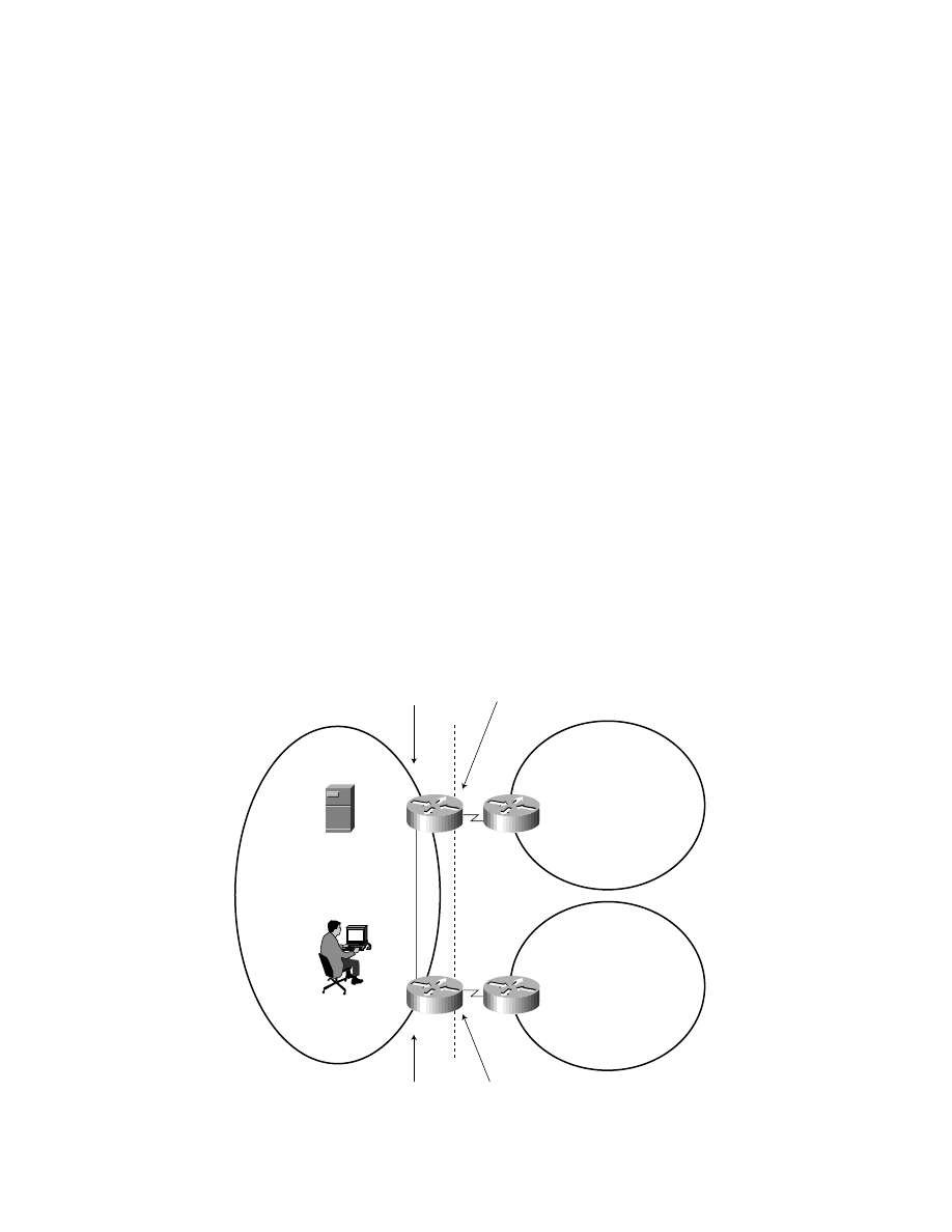
Method 1: “Auto Route Injection”
Consider an example shown in Figure 2. Denote the enterprise border router that connects the enterprise to ISP-A as ENT-BR-A;
denote the enterprise border router that connects the enterprise to ISP-B as ENT-BR-B. Denote the ISP border router that connects
ISP-A to the Enterprise as ISP-BR-A; denote the ISP border router that connects ISP-B to the Enterprise as ISP-BR-B. Denote the
inside global address block that ISP-A allocated to the enterprise as Prefix A; denote the inside global address block that ISP-B
allocated to the enterprise as Prefix B.
Figure 2
“Auto Route Injection”—Steady State
When the set of routes ENT-BR-A receives from ISP-BR-A (via EBGP) has a non-empty intersection with the set of routes ENT-BR-A
receives from ISP-BR-B (via IBGP), ENT-BR-A advertises to ISP-BR-A only the reachability to Prefix A. When the intersection
becomes empty, ENT-BR-A would advertise to ISP-BR-A reachability to both Prefix A and Prefix B. (See Figure 3, where
connectivity between ENT-BR-B and ISP-BR-B is lost). This approach is known as “auto route injection” and would continue for
as long as this connectivity remains down. Once the intersection becomes non-empty, ENT-BR-A would stop advertising
reachability to Prefix B to ISP-BR-A (but would still continue to advertise reachability to Prefix A to ISP-BR-A).
ENT-BR-B
ENT-BR-A
EBGP
ISP A
Enterprise
ISP-BR-B
ISP-BR-A
ISP B
Prefix A
Prefix B
EBGP
IBGP
NAT
NAT

Copyright © 1997 Cisco Systems, Inc. All Rights Reserved.
Page 7 of 25
Figure 3
“Auto Route Injection”—Broken Connection
The approach described above is predicated on the assumption that an enterprise border router has a mechanism(s) by which
it could determine (a) whether the connectivity to the Internet through some other border router of that enterprise is up or down,
and (b) the address prefix that was allocated to the enterprise by the ISP connected to the other border router. One such possible
mechanism could be provided by BGP. In this case, border routers within the enterprise would maintain an IBGP peering
relationship with each other. Whenever one border router determines that the intersection between the set of reachable destinations
it receives via its EBGP (from its directly connected ISP) peers and the set of reachable destinations it receives from another border
router (in the same enterprise) via IBGP is empty, the border router would start advertising to its external peer reachability to the
address prefix that was allocated to the enterprise by the ISP connected to the other border router. The other border router would
advertise (via IBGP) the address prefix that was allocated to the enterprise by the ISP connected to that router.
Each NAT in addition to advertising into the enterprise routing direct reachability to the outside local addresses allocated to
the NAT (as described in “Address Allocation and Routing”), also has to advertise into the enterprise routing direct reachability to
the outside global addresses allocated to the NAT. That, in turn, implies that none of the addresses in the outside global addresses
allocated to the NAT could be used by inside local addresses. This is necessary to avoid disruption of transport connections in the
presence of connectivity failure between the enterprise and its ISPs. In addition, a NAT should inject into the enterprise routing a
default route as long as the NAT determines that it has connectivity to the Internet.
In this method, in a steady state, routes “injected” by the enterprise into its ISPs are aggregated by these ISPs, and are not
propagated into the “default-free” zone of the Internet. It can be argued that, when connectivity is lost, as shown in Figure 3, this
method would result in injecting additional routing information into the “default-free” zone of the Internet. However, one could
observe that the probability of all multi-homed enterprises in the Internet concurrently losing connectivity to the Internet through
one or more of their ISPs is fairly small. Thus on average the number of additional routes in the “default-free” zone of the Internet
due to multi-homed enterprises is expected to be a small fraction of the total number of such enterprises.
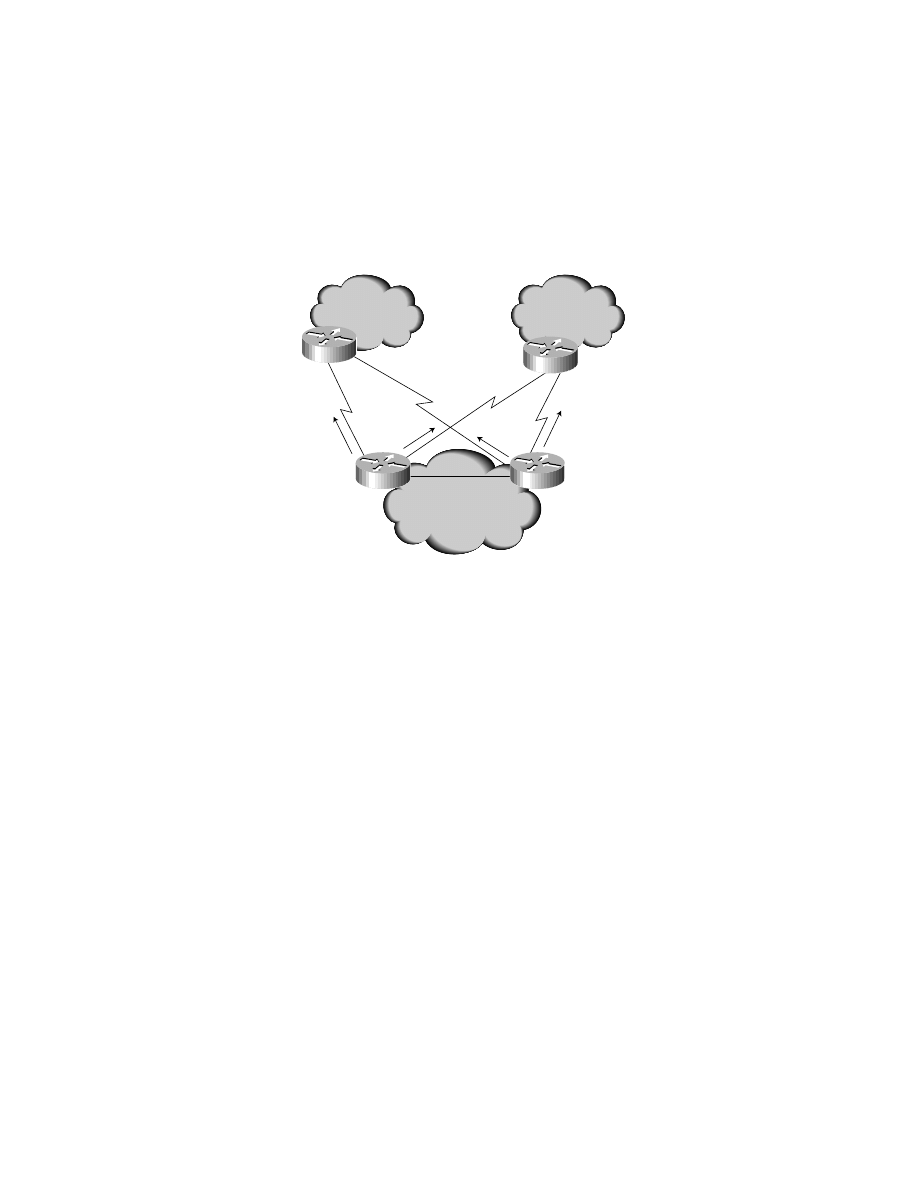
Method 2: “Non-Direct” BGP Peering
The approach described in the previous section allows to significantly reduce the routing overhead in the “default-free” zone of the
Internet due to multi-homed enterprises. The approach described in this section allows to completely eliminate this overhead.
An enterprise border router would maintain EBGP peering not just with the directly connected border router of an ISP, but
with the border router(s) in one or more ISPs that have their border routers directly connected to the other border routers within
the enterprise. Such peering is referred to as “non-direct” EBGP peering. See Figure 4 for a diagram of such a peering arrangement.
ENT-BR-B
ENT-BR-A
EBGP
NAT
NAT
ISP A
Enterprise
ISP-BR-A
ISP B
Prefix A
+
Prefix B
IBGP
Copyright © 1997 Cisco Systems, Inc. All Rights Reserved.
Page 8 of 25
An ISP that maintains both direct and non-direct EBGP peering with a particular enterprise would advertise the same set of
routes over both of these peerings. An enterprise border router that maintains either direct or non-direct peering with an ISP
advertises to that ISP reachability to the address prefix that was allocated by that ISP to the enterprise. Within the ISP, routes received
over direct peering should be preferred over routes received over non-direct peering. Likewise, within the enterprise routes received
over direct peering should be preferred over routes received over non-direct peering. Forwarding along a route received over
non-direct peering should be accomplished via encapsulation [GRE].
Figure 4
“Non-Direct” EBGP Peering—Steady State
As an illustration consider an enterprise connected to two ISPs, as shown in Figure 2. ISP-A and ISP-B. Denote the enterprise border
router that connects the enterprise to ISP-A as E-BR-A, and the ISP-A border router that is connected to ENT-BR-A as ISP-BR-A;
denote the enterprise border router that connects the enterprise to ISP-B as ENT-BR-B, and the ISP-B border router that is connected
to E-BR-B as ISP-BR-B. Denote the inside global addresses block that ISP-A allocated to the enterprise as Prefix A; denote the inside
global addresses block that ISP-B allocated to the enterprise as Prefix B. ENT-BR-A maintains direct EBGP peering with ISP-BR-A
and advertises reachability to Prefix A over that peering. ENT-BR-A also maintain a non-direct EBGP peering with ISP-BR-B and
advertises reachability to Prefix B over that peering. ENT-BR-B maintains direct EBGP peering with ISP-BR-B, and advertises
reachability to Prefix B over that peering. ENT-BR-B also maintains a non-direct EBGP peering with ISP-BR-A, and advertises
reachability to Prefix A over that peering.
When connectivity between the enterprise and both of its ISPs (ISP-A and ISP-B) is up, traffic destined to hosts whose addresses
were assigned out of Prefix A would flow through ISP-A to ISP-BR-A to ENT-BR-A, and then into the enterprise. Likewise, traffic
destined to hosts whose addresses were assigned out of Prefix B would flow through ISP-B to ISP-BR-B to ENT-BR-B, and then into
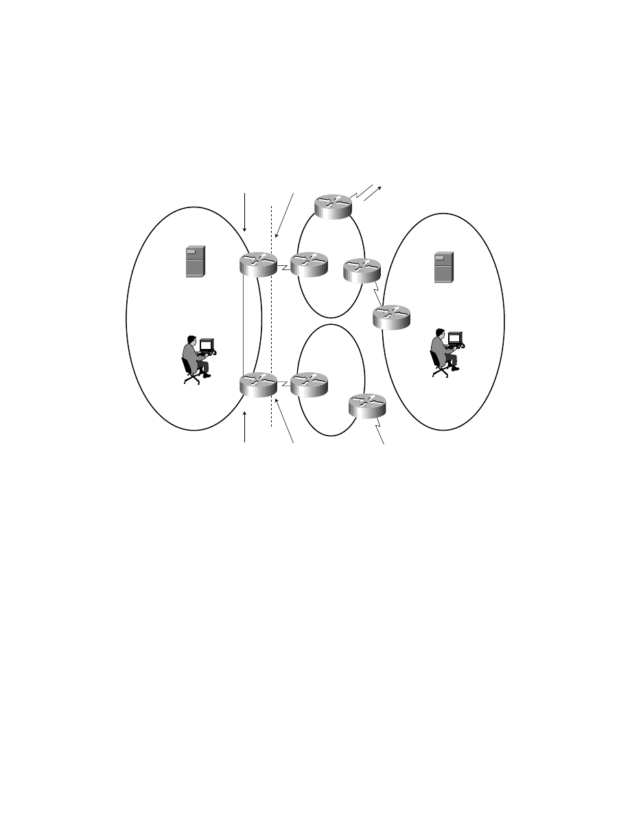
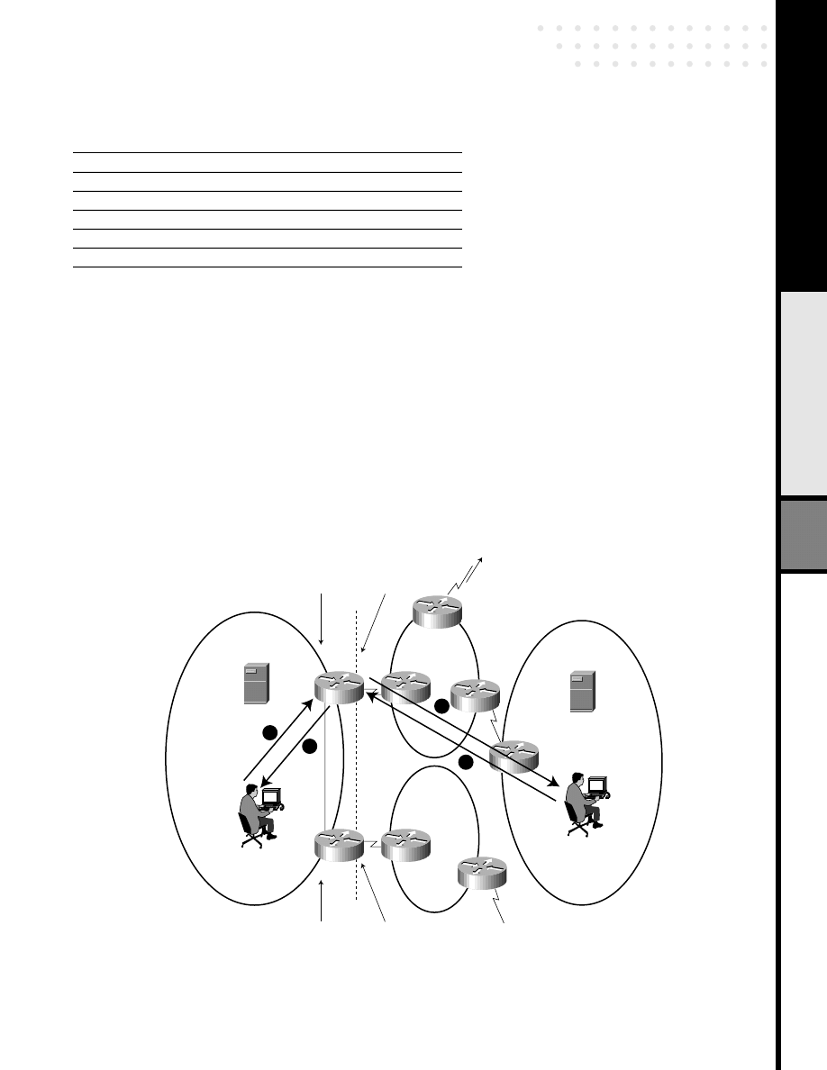
the enterprise. Now consider what would happen when connectivity between ISP-BR-B and ENT-BR-B goes down. In this case
traffic to hosts whose addresses were assigned out of Prefix A would be handled as before. But traffic to hosts whose addresses were
assigned out of Prefix B would flow through ISP-B to ISP-BR-B, ISP-BR-B would encapsulate this traffic and send it to ENT-BR-A,
where the traffic will get decapsulated and then be sent into the enterprise. See Figure 5.
ENT-BR-B
ENT-BR-A
EBGP
ISP A
Enterprise
ISP-BR-B
ISP-BR-A
ISP B
Prefix A
Prefix B
Prefix A
Prefix B
EBGP
IBGP
NAT
NAT

Copyright © 1997 Cisco Systems, Inc. All Rights Reserved.
Page 9 of 25
Figure 5
“Non-Direct” EBGP Peering—Broken Connection
Each NAT in addition to advertising into the enterprise routing direct reachability to the outside local addresses allocated to the
NAT (as described in “Address Allocation and Routing”), also has to advertise into the enterprise routing direct reachability to the
outside global addresses allocated to the NAT. That, in turn, implies that none of the addresses in the outside global addresses
allocated to the NAT could be used by inside local addresses. This is necessary to avoid disruption of transport connections in the
presence of connectivity failure between the enterprise and its ISPs. In addition, a NAT should inject into the enterprise routing a
default route as long as the NAT determines that it has connectivity to the Internet.
Observe that with this scheme there is no additional routing information due to multi-homed enterprises that has to be carried
in the “default-free” zone of the Internet. In addition this scheme does not degrade in the presence of ISPs that filter out routes based
on the length of their address prefixes.
Note also that the set of routers within an ISP that maintain non-direct peering with the border routers within an enterprise
does not have to be restricted to the ISP’s border routers that have direct peering with the enterprise’s border routers. The non-direct
peering could be maintained with any router within the ISP. Doing this could improve the overall robustness in the presence of
failures within the ISP.
Enterprise Hosts that are Outside the Enterprise Network
A DNS zone associated with an enterprise may include one or more hosts that are outside of the enterprise network, i.e. they are
not behind the NATs of the enterprise. To support communication with these hosts, the address translation table of each NAT that
connects the enterprise to the Internet is configured with one inside and one outside address translation type entry per each such
host. In the inside address translation entry the IL address is set to an address from the NAT’s outside local addresses, and the IG
address is set to the IP address of the host. In the outside address translation entry the OL address is set to the IG address of the
inside address translation entry, and the OG address is set to the IL address of the inside address translation entry.
The DNS entry for such host (both A and PTR RR) use the IP address of the host.
ENT-BR-B
ENT-BR-A
EBGP
ISP A
Enterprise
ISP-BR-B
Traffic flows
through GRE
tunnel
ISP-BR-A
ISP B
Prefix A
Prefix B
IBGP
NAT
NAT
Copyright © 1997 Cisco Systems, Inc. All Rights Reserved.
Page 10 of 25
Examples of Operations
In this section we present several examples that illustrate operations of the scheme described in this paper. We use the example
shown in Figure 6 (an extension of Figure 1).
Figure 6
Example multi-homed topology
NAT Configuration
The following commands identify the pool of inside global and outside local addresses available for assignment to NAT1. Also
shown are the required interface commands.
ip nat pool iga 140.16.10.1 140.16.10.254 netmask 255.255.255.0
ip nat pool ola 192.168.1.1 192.168.1.254 netmask 255.255.255.0
ip nat inside source list 1 nat pool iga
ip nat outside source list 2 nat pool ola
access-list 1 permit 10.0.0.0 0.255.255.255
access-list 2 permit any
!
interface s 0
! Link to Upstream ISP
ip address <address> <netmask>
ip nat outside
interface e 0
! Link to Internal Network
ip address <address> <netmask>
ip nat inside
!
ip route 192.168.1.0 255.255.255.0 serial 0; Default route from in-> out
ns.foo.com
10.20.20.10 (IL)
ns.bar.com
35.1.1.42 (OG)
foo.com
10/8 (IL)
bar.com
isp1.com
isp2.com
Host
x.foo.com
10.1.1.1 (IL)
Host
y.bar.com
16.10.10.2 (OG)
DNS
NAT1
NAT2
DNS
140.16/16 (OG)
193.17/16 (OG)
To external DNS at
128.9.0.107 (OG)
(to another ISP
or enterprise)
Outside Local
Address Pool
192.168.2/24 (OL)
Inside Global
Address Pool
193.17.15/24 (IG)
Outside Local
Address Pool
192.168.1/24 (OL)
Inside Global
Address Pool
140.16.10/24 (IG)
EBGP
EBGP
Inside
Outside
IBGP

Copyright © 1997 Cisco Systems, Inc. All Rights Reserved.
Page 11 of 25
The following commands on NAT1 are necessary for the DNS bootstrapping.
! mapping for the internal DNS server
ip nat inside source static 10.20.20.10 140.16.10.254
! mapping for the forwarder
ip nat outside source static 128.9.0.107 192.168.1.254
The following commands on NAT1 are necessary to advertise into interior routing (OSPF) direct reachability to the outside local
addresses.
router ospf 1
redistribute static
ip route 192.168.1.0 255.255.255.0 null 0
The following commands identify the pool of inside global and outside local addresses available for assignment to NAT2. Also
shown are the required interface commands.
ip nat pool iga 193.17.15.1 193.17.15.254 netmask 255.255.255.0
ip nat pool ola 192.168.2.1 192.168.2.254 netmask 255.255.255.0
ip nat inside source list 1 nat pool ola
ip nat outside source list 2 nat pool iga
!
access-list 1 permit 10.0.0.0 0.255.255.255
access-list 2 permit any
!
interface s 0
! Link to Upstream ISP
ip address <address> <netmask>
ip nat outside
interface e 0
! Link to Internal Network
ip address <address> <netmask>
ip nat inside
!
ip route 192.168.2.0 255.255.255.0 serial 0; Default route from in-> out
The following commands on NAT2 are necessary for the DNS bootstrapping.
! mapping for the internal DNS server
ip nat inside source static 10.20.20.10 193.17.15.250
! mapping for the forwarder
ip nat outside source static 128.9.0.107 192.168.2.254
The following commands on NAT2 are necessary to advertise into interior routing (OSPF) direct reachability to the outside local
addresses.
router ospf 1
redistribute static
ip route 192.168.2.0 255.255.255.0 null 0

Copyright © 1997 Cisco Systems, Inc. All Rights Reserved.
Page 12 of 25
Mapping for DNS Servers
The address translation tables maintained by NATs have to be preconfigured to enable communication between the DNS server(s)
within the enterprise, and the DNS server(s) that outside the enterprise that the DNS server(s) within the enterprise use to resolve
DNS queries.
We assume the following DNS scenario throughout this paper:
1. Clients in the foo.com domain use ns.foo.com as their default DNS server.
2. All DNS queries which cannot be handled out of the ns.foo.com cache are forwarded, either through NAT1 or NAT2, to an
external DNS server at 128.9.0.107 (OG).
3. The ns.foo.com DNS server provides recursive resolution.
4. Clients in the bar.com domain use ns.bar.com as their default DNS server.
5. The ns.bar.com DNS server provides recursive resolution.
DNS Configuration
Shown below are the DNS files for the DNS server (ns.foo.com) inside the enterprise that is authoritative for the foo.com zone. Note
that these configuration files do not fully represent all the necessary configuration that may be needed in an operational
environment.
Setting Up a Boot File
Here we configure db.foo as the database for local host name to address mappings, db.10 as the database for local address to host
name mapping.
;
BSDI
$Id: named.boot.sample,v 2.1 1996/01/16 17:39:49 polk Exp $
;
@(#)named.boot8.1 (Berkeley) 6/9/93
directory/etc/namedb
primary foo.com
db.foo
primary10.in-addr.arpa
db.10
;
; the following two lines are for handling queries for PTR RRs for hosts outside the
; enterprise
primary1.168.192.in-addr.arpa
db.192.168.1
primary2.168.192.in-addr.arpa
db.192.168.2
;
forwarders
192.168.1.254 192.168.2.254; Outside Local addresses
options
forward-only
;
primary 0.0.127.in-addr.arpa localhost.rev
db.foo file
The file db.foo contains the name to address mappings for hosts within the enterprise
;
@
IN
SOA
ns.foo.com.hostmaster.ns.foo.com. (
2
; Serial number
3600
; Refresh every 2 days
3600
; Retry every hour
3600
; Expire every 20 days
3600
(?)
Minimum 2 days

Copyright © 1997 Cisco Systems, Inc. All Rights Reserved.
Page 13 of 25
;
; Name Servers
foo.com.
IN
NS
ns.foo.com.
;
; Addresses
ns.foo.com.
IN
A
10.20.20.10
; Inside Local address
;
x.foo.com.
IN
A
10.1.1.1
; Inside Local address
;
nat1-ns.foo.com.
IN
A
192.168.1.254
; Outside Local address
nat2-ns.foo.com.
IN
A
192.168.2.254
; Outside Local address
db.10 File
The file db.10 contains mapping of internal local addresses to host names.
;
; Reverse address resolution for local network addresses
;
@
IN
SOA
ns.foo.com.
hostmaster.ns.foo.com. (
2
; Serial number
600
; Refresh every 2 days
3600
; Retry every hour
600
; Expire every 20 days
600(?) Minimum 2 days
;
; Name Servers
10.in-addr.arpa.
IN
NS
ns.foo.com.
;
; Addresses
10.20.20.10.in-addr.arpa
IN
PTR
ns.foo.com.
1.1.1.10.in-addr.arpa
IN
PTR
x.foo.com.
;
db.192.168.1
The file db.192.168.1 contains information needed to resolve DNS Queries for PTR RRs that are originated within the enterprise:
;
; Reverse address resolution for local network addresses
;
@
IN
SOA
nat1-ns.foo.com.hostmaster.nat1-ns.foo.com. (
2
; Serial number
600
; Refresh every 2 days
3600
; Retry every hour
600
; Expire every 20 days
600(?) Minimum 2 days
;
1.168.192.in-addr.arpa.IN
NS
nat1-ns.foo.com.

Copyright © 1997 Cisco Systems, Inc. All Rights Reserved.
Page 14 of 25
db.192.168.2
The file db.192.168.2 contains information needed to resolve DNS Queries for PTR RRs that are originated within the enterprise:
;
; Reverse address resolution for local network addresses
;
@
IN
SOA
nat2-ns.foo.com.hostmaster.nat2-ns.foo.com. (
2
; Serial number
600
; Refresh every 2 days
3600
; Retry every hour
600
; Expire every 20 days
600(?) Minimum 2 days
;
2.168.192.in-addr.arpa.IN
NS
nat2-ns.foo.com.
When the NATs are configured as previously described, the address translation table maintained by NAT1 contains the following
entries:
Table 1 NAT1 Table
The first pair of entries in the table enable the ns.foo.com DNS server to be reachable to external hosts via the IG address
140.16.10.254. The second pair of entries in the table enable clients in the foo.com domain to reach their default external DNS
server via OL address 192.168.1.254.
Likewise, the address translation table maintained by NAT2 contains the following entries:
Table 2 NAT2 Table
Setting Up the “Glue”
To delegate the subdomain that corresponds to the 140.16.10/24 inside global addresses block, a DNS server authoritative for the
16.140.in-addr.arpa has to contain the following:
10.16.140.in-addr.arpa.
86400
IN
NS
foo-ns.isp1.com.
The DNS server authoritative for the isp1.com zone has to contain the following:
foo-ns.isp1.com.
IN
A
140.16.10.254
Original Address (OA)
Type
Translated Address (TA)
Type
10.20.20.10
IL
140.16.10.254
IG
140.16.10.254
IG
10.20.20.10
IL
192.168.1.254
OL
128.9.0.107
OG
128.9.0.107
OG
192.168.1.254
OL
Original Address (OA)
Type
Translated Address (TA)
Type
10.20.20.10
IL
193.17.15.250
IG
193.17.15.250
IG
10.20.20.10
IL
192.168.2.254
OL
128.9.0.107
OG
128.9.0.107
OG
192.168.2.254
OL

Copyright © 1997 Cisco Systems, Inc. All Rights Reserved.
Page 15 of 25
Note that this causes all DNS Queries for PTR RRs with addresses taken of the inside global 140.16.10/24 block to be handled
by NAT1.
To delegate the subdomain that corresponds to the 193.17.15/24 inside global addresses block, a DNS server authoritative for
the 17.193.in-addr.arpa has to contain the following:
15.17.193.in-addr.arpa.86400 IN
NS
foo-ns.isp2.com.
The DNS server authoritative for the isp2.com zone has to contain the following:
foo-ns.isp2.com.
IN
A
193.17.15.250
Note that this causes all DNS Queries for PTR RRs with addresses taken of the inside global 193.17.15/24 block to be handled by
NAT2.
A DNS server authoritative for the foo’s parent zone (“.com” DNS server) must contain the following:
foo
86400
IN
NS
ns.foo.com.
;
ns.foo.com.
86400
IN
A
140.16.10.254 ; Inside Global address
IN
A
193.17.15.250 ; Inside Global address
Note that because the enterprise has two NATs, we have two A RR (even if there is only one DNS server within the enterprise).
Internally Originated Connection
In this section we describe the operations where a host inside an enterprise originates a connection to a host outside the enterprise.
Consider the example shown in Figure 5, where host x.foo.com inside an enterprise wants to establish communication with host
y.bar.com that is outside the enterprise.
First, the DNS server inside foo.com (ns.foo.com) sends a query to one of its preconfigured DNS servers outside the enterprise.
Let’s assume that the query is sent to the address 192.168.1.254. In this case the Query will be routed to NAT1 (as NAT1 advertises
direct reachability to 192.168.1/24 into enterprise routing). NAT1 finds in its address translation table an outside address
translation type entry whose OL address is equal to 192.168.1.254, and then replaces the destination address in the packet with the
OG address of the found entry (128.9.0.107). Next NAT1 finds in its address translation table an inside address translation type
entry whose IL address is equal to 10.20.20.10, and then replaces the source address in the packet with the IG address of the found
entry (140.16.10.254). In this fashion, both source and destination addresses are translated by the NAT.
When the Query reaches the external DNS server, the server resolves the Query, and composes a Response. The external DNS
server then sends the Response towards NAT1 since the destination IP address in the packet that carries the Response is
140.16.10.254 (IG).
When NAT1 receives the Response, NAT1 finds that its address translation table does not have an outside address translation
type entry whose OG address is equal to the address of y.bar.com (16.10.10.2) carried in the A RR of the Response. Therefore,
NAT1 (a) creates a new outside address translation type entry, (b) sets the OG address of the entry to the IP address carried in the
A RR of the Response (16.10.10.2), (c) dynamically allocates an address 192.168.1.5 out of its outside local addresses block, (d)
sets the OL address of the entry to this address, and (e) replaces the IP address carried in the A RR of the Response with this address.
This completes the creation of a new outside address translation type entry. The modified Response is then sent to the DNS server
inside the enterprise, which in turn, sends it to x.foo.com. See Figure 5 below for details:
Note:
If NAT1 is unavailable and/or the ns.foo.com DNS server does not receive a DNS response, ns.foo.com will then re-send the
DNS query to 192.168.2.254, the second DNS server in its list of forwarders. This is the OL address corresponding to an external
default DNS server as reachable through NAT2. Thus, if NAT1 is unavailable, the DNS query will be reissued to an external DNS
server via NAT2. NAT2 then routes the DNS query and subsequent packet flow as described below. In this fashion, DNS can
provides link redundancy in dual-NAT connectivity implementations.
Copyright © 1997 Cisco Systems, Inc. All Rights Reserved.
Page 16 of 25
Figure 7
Internally Originated DNS Request from x.foo.com for y.bar.com
Table 3
*Between steps 4 and 5, the OG address 10.1.1.1 returned in the DNS “A” RR response for y.bar.com is dynamically translated to an address from the OL pool. Here we assume the
address 192168.1.5. As a result, x.foo.com “sees” y.bar.com at 192.168.1.5 (OL).
Once the steps have been taken as described in Figure 7, the address translation table maintained by NAT1 contains the following
entries:
Step
Source Address
Type
Destination Address
Type
1
10.1.1.1
IL
10.20.20.10
IL
2
10.20.20.10
IL
192.168.1.254
OL
3
140.16.10.254
IG
128.9.0.107
OG
4
128.9.0.107
OG
140.16.10.254
IG
5*
192.168.1.254
OL
10.20.20.10
IL
6
10.20.20.10
IL
10.1.1.1
IL
ns.foo.com
10.20.20.10 (IL)
ns.bar.com
35.1.1.42 (OG)
isp1.com
isp2.com
Host
x.foo.com
10.1.1.1 (IL)
Host
y.bar.com
16.10.10.2 (OG)
DNS
NAT1
NAT2
DNS
140.16/16 (OG)
193.17/16 (OG)
To external DNS at
128.9.0.107 (OG)
(to another ISP
or enterprise)
Outside Local
Address Pool
192.168.2/24 (OL)
Inside Global
Address Pool
193.17.15/24 (IG)
Outside Local
Address Pool
192.168.1/24 (OL)
Inside Global
Address Pool
140.16.10/24 (IG)
EBGP
EBGP
Inside
Outside
bar.com
foo.com
2
3
1
6
5
4
IBGP
Copyright © 1997 Cisco Systems, Inc. All Rights Reserved.
Page 17 of 25
Table 4 NAT1 Table
First Data Packet
Now consider what happens when x.foo.com sends a packet to y.bar.com (see Figure 8). The packet destination address is set to
192.168.1.5, and since NAT1 advertises direct reachability to 192.168.1/24 into the enterprise routing, the packet is routed to
NAT1. When NAT1 receives the packet, NAT1 searches its address translation table for an outside address translation type entry
with OL address equal to the destination address in the packet. Once the entry is found, NAT1 replaces the destination address
(192.68.1.5) with the OG address from the found entry (16.10.10.2). After that NAT1 finds no inside address translation type entry
with IL address equal to the IP source address in the packet. Therefore, NAT1 dynamically creates a new entry of type inside address
translation, sets the IL address of the entry to the source address of the packet (10.1.1.1), and allocates an address (140.16.10.2)
out of its inside global addresses block for that address. That completes the creation of the inside address translation type entry.
NAT1 then replaces the source address in the packet (10.1.1.1) with the IG address translation (140.16.10.2) and the packet is sent
to y.bar.com. Note that data flows will always traverse the same NAT router which translate the initial DNS query payload.
Figure 8
Internally Initiated Packet Flow from x.foo.com to y.bar.com
Original Address (OA)
Type
Translated Address (TA)
Type
10.20.20.10
IL
140.16.10.254
IG
140.16.10.254
IG
10.20.20.10
IL
192.168.1.254
OL
128.9.0.107
OG
128.9.0.107
OG
192.168.1.254
OL
192.168.1.5
OL
16.10.10.2
OG
16.10.10.2
OG
192.168.1.5
OL
ns.foo.com
10.20.20.10 (IL)
ns.bar.com
35.1.1.42 (OG)
isp1.com
isp2.com
Host
x.foo.com
10.1.1.1 (IL)
Host
y.bar.com
16.10.10.2 (OG)
DNS
NAT1
NAT2
DNS
140.16/16 (OG)
193.17/16 (OG)
To external DNS at
128.9.0.107 (OG)
(to another ISP
or enterprise)
Outside Local
Address Pool
192.168.2/24 (OL)
Inside Global
Address Pool
193.17.15/24 (IG)
Outside Local
Address Pool
192.168.1/24 (OL)
Inside Global
Address Pool
140.16.10/24 (IG)
EBGP
EBGP
Inside
Outside
bar.com
2
1
4
3
IBGP
foo.com

Copyright © 1997 Cisco Systems, Inc. All Rights Reserved.
Page 18 of 25
Table 5
*Because no entry for IL address 10.1.1.1 exists in the NAT table for x.foo.com at step 1, a dynamic translation to an address from the IG pool is created. Here we assume the address
is 140.16.10.2(IG).
Once the steps have been taken as described in Figure 6, the address translation table maintained by NAT1 contains the following
entries:
Table 6 NAT1 Table
Observe that at this point NAT1 has all the necessary entries to support communication between x.foo.com and y.bar.com.
Query for PTR RR
When x.foo.com sends a Query for PTR RR associated with y.bar.com, the QNAME field in the Question section of the Query
contains 5.1.168.192.in-addr.arpa. The ns.foo.com DNS server notices (from its configuration) that such Query should be sent to
192.168.1.254 (OL). When the Query reaches NAT1, it replaces the 10.20.20.10 (IL) source IP address in the packet with
140.16.10.254 (IG). It also replaces the 192.168.1.254 (OL) destination IP address in the packet with 128.9.0.107 (OG), and
replaces 5.1.168.192 in the QNAME field with 2.10.10.16.
The Response to the Query carries 2.10.10.16 in the QNAME field, and also contains a PTR RR that carries 16.10.10.2. When
the Response reaches NAT1, it replaces 2.10.10.16 in the QNAME field with 5.1.168.192 and 16.10.10.2 (OG) in the PTR RR
with 192.168.1.5 (OL). NAT1 then translates the source and destination addresses, and sends the Response to ns.foo.com DNS
server inside foo.com, which in turn sends it to x.foo.com.
Externally Originated Connection
In this section we describe the operations where a host outside an enterprise originates a connection to a host inside the
enterprise.
Consider the example shown in Figure 9, where host y.bar.com wants to establish communication with host x.foo.com
(y.bar.com is outside the enterprise). Assume that the DNS server inside bar.com does not have any information about DNS servers
authoritative for the foo.com zone.
Step
Source Address
Type
Destination Address
Type
1
10.1.1.1
IL
192.168.1.5
OL
2
140.16.10.2*
IG
16.10.10.2
OG
3
16.10.10.2
OG
140.16.10.2*
IG
4
140.16.10.2
OL
10.1.1.1
IL
Original Address (OA)
Type
Translated Address (TA)
Type
10.20.20.10
IL
140.16.10.254
IG
140.16.10.254
IG
10.20.20.10
IL
192.168.1.254
OL
128.9.0.107
OG
128.9.0.107
OG
192.168.1.254
OL
192.168.1.5
OL
16.10.10.2
OG
16.10.10.2
OG
192.168.1.5
OL
140.16.10.2
IG
10.1.1.1
IL
10.1.1.1
IL
140.16.10.2
IG

Copyright © 1997 Cisco Systems, Inc. All Rights Reserved.
Page 19 of 25
Finding DNS Server Authoritative for foo.com
To determine the IP address of the DNS server authoritative for the foo.com zone the DNS server inside bar.com (whose IP address
is assumed to be 35.1.1.42) sends a Query to one of the DNS servers authoritative for the foo’s parent zone (presumably the “.com”
DNS server). The server in the parent’s zone returns in the Response two A RRs, one that contains 140.16.10.254 (IG) and another
that contains 193.17.15.250 (IG). These two addresses correspond to the internal ns.foo.com DNS server as reachable from the
outside via NAT1 and NAT2, respectively.
Communication with the DNS Server Authoritative for foo.com
After the server in the bar.com zone finds addresses of the server authoritative for the foo.com zone, the server in the bar.com zone
sends a Query message to one of these addresses. Let’s assume that the Query is sent to the address 140.16.10.254 (IG). In this case
the Query will be routed to NAT1 (as NAT1 advertises direct reachability to 140.16.10/24 into the Internet routing).
NAT1 finds in its address translation table an inside address translation type entry whose IG address is equal to 140.16.10.254,
and then replaces the destination address in the packet with the IL address of the found entry (10.20.20.10). Next NAT1 finds that
there is no outside address translation type entry whose OG address is equal to the source address in the packet (35.1.1.42), and
then (a) creates a new outside address translation type entry, (b) sets the OG address in the entry to 35.1.1.42, (c) allocates an
address 192.168.1.253 out of its outside local addresses, and (d) sets the OL address of the entry to 192.168.1.253. After that NAT1
replaces the 35.1.1.42 (OG) source address in the packet with 192.168.1.253 (OL).
When the Query reaches the DNS server authoritative for the foo.com zone - ns.foo.com at 10.20.20.10 (IL), the server
composes a Response and sends it back. The Response is forwarded towards NAT1 (since the destination IP address in the packet
that carries the response is 192.168.1.253 (OL).
When NAT1 receives the Response that contains an A RR (for x.foo.com), NAT1 finds that its address translation table does
not have an inside address translation type entry whose IL address is equal to the address carried in the A RR of the Response.
Therefore NAT1 (a) creates a new inside address translation type entry, (b) sets the IL address of the entry to 10.1.1.1 (the address
carried in the A RR), (c) allocates an address 140.16.10.2 out of its inside global addresses, (d) sets the IG address of the entry to
140.16.10.2, and (e) replaces 10.1.1.1 (IL) in the A RR carried by the Response with 140.16.10.2 (IG). See Figure 9 for details:
Copyright © 1997 Cisco Systems, Inc. All Rights Reserved.
Page 20 of 25
Figure 9
Externally Originated DNS Query from y.bar.com for x.foo.com
Table 7
*Between steps 4 and 5, the IL address 10.1.1.1 returned in the DNS “A” RR response for x.foo.com is dynamically translated to an address from the IG pool. Here we assume the IG
address 140.16.10.2 As a result, y.bar.com “sees” x.foo.com at 140.16.10.2 (IG).
Step
Source Address
Type
Destination Address
Type
1
16.10.10.2
OG
35.1.1.42
OG
2
35.1.1.42
OG
140.16.10.254
IG
3
192.168.1.253
OL
10.20.20.10
IL
4
10.20.20.10
IL
192.168.1.253
OL
5*
140.16.1.254
IG
35.1.1.42
OG
6
35.1.1.42
OG
16.10.10.2
OG
-
ns.foo.com
10.20.20.10 (IL)
ns.bar.com
35.1.1.42 (OG)
isp1.com
isp2.com
Host
x.foo.com
10.1.1.1 (IL)
Host
y.bar.com
16.10.10.2 (OG)
DNS
NAT1
NAT2
DNS
140.16/16 (OG)
193.17/16 (OG)
To external DNS at
128.9.0.107 (OG)
(to another ISP
or enterprise)
Outside Local
Address Pool
192.168.2/24 (OL)
Inside Global
Address Pool
193.17.15/24 (IG)
Outside Local
Address Pool
192.168.1/24 (OL)
Inside Global
Address Pool
140.16.10/24 (IG)
EBGP
EBGP
Inside
Outside
bar.com
2
5
1
6
4
3
IBGP
foo.com

Copyright © 1997 Cisco Systems, Inc. All Rights Reserved.
Page 21 of 25
Once the steps have been taken as described in Figure 9, the address translation table maintained by the NAT contains the following
entries:
Table 8 NAT1 Table
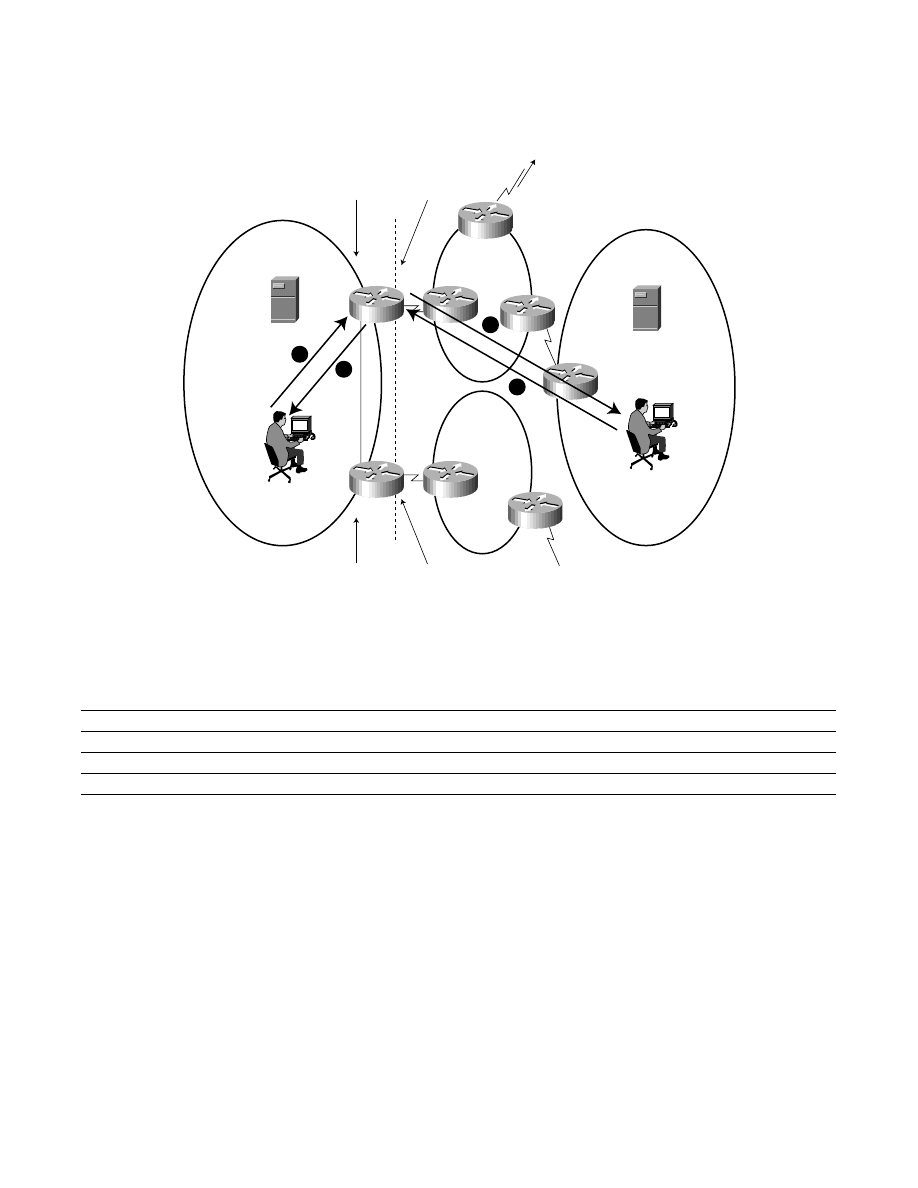
First Data Packet
Now consider what happens when y.bar.com sends a packet to x.foo.com (see Figure 10). The packet destination address is set to
140.16.10.2 (IG), and since NAT1 advertises direct reachability to 140.16.10/24 into Internet routing, the packet is routed to
NAT1. When NAT1 receives the packet, it finds an inside address translation type entry with IL address equal to the IP destination
address in the packet. Therefore, NAT1 replaces the 140.16.10.2 (IG) destination address with the OG address from the found entry
(192.168.1.5). Next NAT1 finds that its address translation table does not have an outside address translation type entry whose
OG address is equal to the IP source address in the packet. Therefore, NAT1 (a) creates a new outside address translation type entry,
(b) sets the OG address of the entry to the source address of the packet (16.10.10.2), (c) allocates an address 192.168.1.5 out of its
outside local addresses block, and (d) sets the OL address of the entry to that address. That completes the creation of the outside
address translation type entry. NAT1 then replaces the source address in the packet (16.10.10.2) with the OL address of the entry
(192.168.1.5) and the packet is sent to x.foo.com. In this fashion, both the source and destination addresses are translated by the
NAT. Note that data flows will always traverse the same NAT router which translate the initial DNS query payload.
Original Address (OA)
Type
Translated Address (TA)
Type
10.20.20.10
IL
140.16.10.254
IG
140.16.10.254
IG
10.20.20.10
IL
192.168.1.254
OL
128.9.0.107
OG
128.9.0.107
OG
192.168.1.254
OL
192.168.1.253
OL
35.1.1.42
OG
35.1.1.42
OG
192.168.1.253
OL
10.1.1.1
IL
140.16.10.2
IG
140.16.10.2
IG
10.1.1.1
IL
Copyright © 1997 Cisco Systems, Inc. All Rights Reserved.
Page 22 of 25
Figure 10
Externally Originated Packet Flow from y.bar.com to x.foo.com
Table 9
*Because no entry for OG address 16.10.10.2 exists in the NAT table for y.bar.com at step 1, a dynamic translation to an address from the OL pool is created. Here we assume the
address is 192.168.1.5 (OL).
Step
Source Address
Type
Destination Address
Type
1
16.10.10.2
OG
140.16.10.2
IG
2
192.168.1.5*
OL
10.1.1.1
IL
3
10.1.1.1
IL
192.168.1.5*
OL
4
140.16.10.2
IG
16.10.10.2
OG
ns.foo.com
10.20.20.10 (IL)
ns.bar.com
35.1.1.42 (OG)
isp1.com
isp2.com
Host
x.foo.com
10.1.1.1 (IL)
Host
y.bar.com
16.10.10.2 (OG)
DNS
NAT1
NAT2
DNS
140.16/16 (OG)
193.17/16 (OG)
To external DNS at
128.9.0.107 (OG)
(to another ISP
or enterprise)
Outside Local
Address Pool
192.168.2/24 (OL)
Inside Global
Address Pool
193.17.15/24 (IG)
Outside Local
Address Pool
192.168.1/24 (OL)
Inside Global
Address Pool
140.16.10/24 (IG)
EBGP
EBGP
Inside
Outside
bar.com
4
3
2
1
IBGP
foo.com

Copyright © 1997 Cisco Systems, Inc. All Rights Reserved.
Page 23 of 25
Once the steps have been taken as described in Figure 10, the address translation table maintained by the NAT contains the
following entries:
Table 10 NAT1 Table
Query for PTR RR
When y.bar.com sends a Query for PTR RR associated with x.foo.com, the QNAME field in the Question section of the Query
contains 2.10.16.140.in-addr.arpa. The “glue” RR in the DNS server authoritative for the 16.140.in-addr.arpa zone indicates that
the address of the DNS server authoritative for the 10.16.140.in-addr.arpa zone is 140.16.10.254 (IG). Thus the Query would be
sent to NAT1. When the Query reaches NAT1, it replaces 2.10.16.140 in the QNAME field with 1.1.1.10, and sends the Query to
the DNS server inside the enterprise.
The Response to the Query from the DNS server inside the enterprise would carry 1.1.1.10 in the QNAME field, and will also
contain a PTR RR that carries 10.1.1.1 (IL) (as well as the name of the host - x.foo.com). When the Response reaches NAT1,
following the procedures described in Sections 0, NAT1 replaces 1.1.1.10 in the QNAME field and in the PTR RR with 2.10.16.140,
and 10.1.1.1 (IL) in the PTR RR with 140.16.10.2 (IG).
Benefits
Decreases impact of Changing Service Providers
A multi-homed enterprise using the architecture outlined in this paper can change its service provider(s) and limit the impact of such
a change to external addressing and routing. Specifically, such a change does not require renumbering of any hosts and/or routers
inside the enterprise. When such an enterprise connects to a new ISP, the enterprise must acquire a block of address (address prefix)
out of that ISP’s address space, configure this block of addresses as the inside global addresses block on the NAT(s) that the
enterprise uses to connect to that ISP, configure BGP peering between the NAT(s) and the border routers of the ISP, and then
advertise to the ISP direct reachability to the inside global address block(s) of the NAT(s).
Routing Symmetry
The scheme described in this paper results in a situation where a traffic associated with a particular pair of hosts (where one host
is inside the enterprise and the other is outside the enterprise) flows through a single NAT. As a consequence, this traffic flows
bi-directionally through the same ISP connected to the enterprise.
Load Distribution
One could observe that DNS plays an important role in selecting which of the NATs is used by a particular connection. This suggests
to use DNS as a tool to distribute load among multiple NATs that connect an enterprise to the Internet. Specifically, by controlling
the selection of a NAT that is used for forwarding a DNS Query, one could control the selection of a NAT that is used for
Original Address (OA)
Type
Translated Address (TA)
Type
10.20.20.10
IL
140.16.10.254
IG
140.16.10.254
IG
10.20.20.10
IL
192.168.1.254
OL
128.9.0.107
OG
128.9.0.107
OG
192.168.1.254
OL
192.168.1.253
OL
35.1.1.42
OG
35.1.1.42
OG
192.168.1.253
OL
10.1.1.1
IL
140.16.10.2
IG
140.16.10.2
IG
10.1.1.1
IL
192.168.1.5
OL
16.10.10.2
OG
16.10.10.2
OG
192.168.1.5
OL

Copyright © 1997 Cisco Systems, Inc. All Rights Reserved.
Page 24 of 25
communication with the target of that Query. In our previous examples, since the Query for y.bar.com is handled by NAT1,
communication with y.bar.com (which is a target of that Query) is handled by NAT1 as well. Conversely, if the Query is handled
by NAT2, the communication would be handled by NAT2.
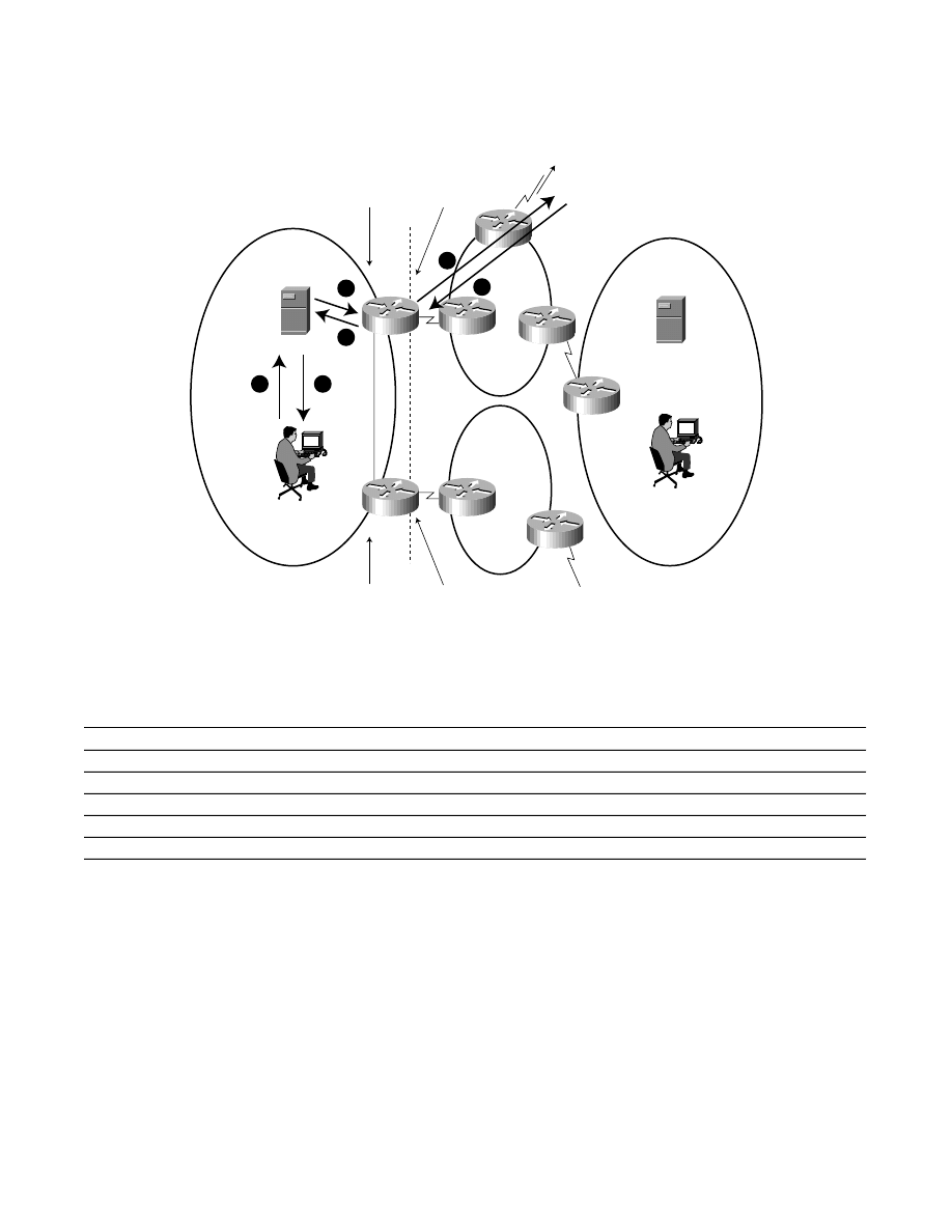
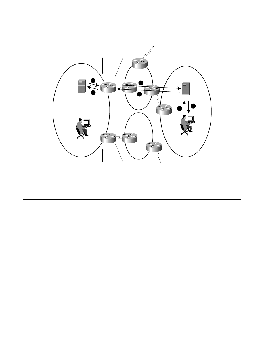
One possible strategy to control the distribution of internally originated connections among multiple NATs is to use multiple
internal DNS servers. As an illustration consider the example shown in Figure 11.
In this scenario, DNS-Server-1 and DNS-Server-2 are each configured with two DNS forwarders: one with an outside local
address on NAT1, and one with an outside local address on NAT2. Precisely, DNS-Server-1’s inside local address to inside global
address mapping is configured on both NAT1 and NAT2. The same mapping is configured for DNS-Server-2. DNS-Server-1 is
configured with a primary external DNS forwarder whose outside local address is taken out of the NAT1’s outside local addresses
block, and a secondary forwarder whose outside local address is taken out of the NAT2’s outside local addresses block. Likewise,
DNS-Server-2 is configured with a primary external DNS forwarder whose outside local address is taken out of the NAT2’s outside
local addresses block, and a secondary DNS forwarder whose outside local address is taken out of the NAT1’s outside local
addresses block.
As a result, in a steady state all the DNS Queries originated by DNS-Server-1 are handled by NAT1, and all the DNS Queries
originated by DNS-Server-2 are handled by NAT2. Consequently if a host (e.g., Host-A) inside an enterprise is configured to use
DNS-Server-1, then in a steady state all connections originated by that host are handled by NAT1. Likewise, if a host (e.g., Host-B)
is configured to use DNS-Server-2, then in a steady state all connections originated by that host are handled by NAT2.
If connectivity to NAT1, or connectivity to Network A’s primary DNS forwarder, is lost, all new DNS queries and subsequent
data flows initiated by hosts in Network A will be routed via NAT2, along with all DNS queries and packet flows initiated by hosts
in Network B. Conversely, if connectivity to NAT2, or connectivity to Network B’s primary DNS forwarder, is lost, all new DNS
queries and subsequent data flows initiated by hosts in Network B will be routed via NAT1, along with all DNS queries and packet
flows initiated by hosts in Network A. Thus, such a dual-DNS/dual-NAT configuration provides both NAT load distribution and
NAT failover.
Figure 11
Network A
Enterprise
Host A
DNS-Server-1
NAT1
Network B
ISP 2
ISP 1
Host B
DNS-Server-2
NAT2

Corporate Headquarters
Cisco Systems, Inc.
170 West Tasman Drive
San Jose, CA 95134-1706
USA
http://www.cisco.com
Tel: 408 526-4000
800 553-NETS (6387)
Fax: 408 526-4100
European Headquarters
Cisco Systems Europe s.a.r.l.
Parc Evolic, Batiment L1/L2
16 Avenue du Quebec
Villebon, BP 706
91961 Courtaboeuf Cedex
France
http://www-europe.cisco.com
Tel: 33 1 6918 61 00
Fax: 33 1 6928 83 26
Copyright © 1998 Cisco Systems, Inc. All rights reserved. Printed in USA. AccessPath, and Cisco IOS are trademarks; Cisco, Cisco Systems, and the Cisco Systems logo are registered trademarks of
Cisco Systems, Inc. in the U.S. and certain other countries. All other trademarks mentioned in this document are the property of their respective owners.
2/98 SP
Cisco Systems has more than 200 offices in the following countries. Addresses, phone numbers, and fax numbers are listed on the
C i s c o C o n n e c t i o n O n l i n e W e b s i t e a t h t t p : / / w w w . c i s c o . c o m .
Argentina
•
Australia
•
Austria
•
Belgium
•
Brazil
•
Canada
•
Chile
•
China (PRC)
•
Colombia
•
Costa Rica
•
Czech Republic
•
Denmark
England
•
France
•
Germany
•
Greece
•
Hungary
•
India
•
Indonesia
•
Ireland
•
Israel
•
Italy
•
Japan
•
Korea
•
Luxembourg
•
Malaysia
Mexico
•
The Netherlands
•
New Zealand
•
Norway
•
Peru
•
Philippines
•
Poland
•
Portugal
•
Russia
•
Saudi Arabia
•
Scotland
•
Singapore
South Africa
•
Spain
•
Sweden
•
Switzerland
•
Taiwan, ROC
•
Thailand
•
Turkey
•
United Arab Emirates
•
United States
•
Venezuela
Americas
Headquarters
Cisco Systems, Inc.
170 West Tasman Drive
San Jose, CA 95134-1706
USA
http://www.cisco.com
Tel: 408 526-7660
Fax: 408 527-0883
Asia Headquarters
Nihon Cisco Systems K.K.
Fuji Building, 9th Floor
3-2-3 Marunouchi
Chiyoda-ku, Tokyo 100
Japan
http://www.cisco.com
Tel: 81 3 5219 6250
Fax: 81 3 5219 6001
By appropriately configuring hosts with the addresses of their default DNS server(s), the administration of the enterprise can control
distribution of internally originated connections among its connections to the Internet. Controlling which hosts use a particular
DNS server can be facilitated by using DHCP as well.
It is important to observe that the selection of a NAT is not affected by the interior routing inside an enterprise. As a result,
changes in interior routing do not affect the selection of which NAT is used for a particular communication.
Single NAT to Multiple ISPs
A degenerate case of the scheme described in this paper is a scenario where a NAT is connected to multiple ISPs. In this case the
NAT obtains out of each of these ISP a block of addresses that the NAT uses as its inside global addresses. Thus, the single NAT
would advertise reachability to two inside global address prefixes (sub-prefixes of the ISP’s address space), rather than one. To use
DNS for load balancing one could deploy multiple DNS servers as previously described.
Bibliography
[RFC1631] - “The IP Network Address Translator (NAT)”—K. Egevang, P. Francis
[RFC1034] - “Domain Names - Concepts and Facilities”—P. Mockapetris
[RFC1035] - “Domain Names - Implementation and Specification”—P. Mockapetris
[RFC1918] - Address Allocation for Private Internets, Y. Rekhter, B. Moskowitz, D. Karrenberg, G. J. de Groot, E. Lear
[RFC2008] - “Implications of Various Address Allocation Policies for Internet Routing”—Y. Rekhter, T. Li
[RFC2260] - “Scalable Support for Multi-homed Multi-provider Connectivity”—T. Bates, Y. Rekhter
Wyszukiwarka
Podobne podstrony:
NS2 lab 4 4 7 en Configure Cisco IOS IPSec using Pre Shared Keys
Cisco IOS Firewall Intrusion Detection System(1)
CCNA Lab02 5 4 podstawowa konfiguracja routera za pomocą linii poleceń CISCO IOS
NS1 lab 8 3 13 en Configure Cisco IOS Firewall CBAC
Cisco Designing Network Security
hakin9 6 2004 cisco ios demo
Asterisk With Cisco IP Phones
Configuring Cisco IOS Firewall Intrusion
NS2 lab 4 4 7 en Configure Cisco IOS IPSec using Pre Shared Keys
Cisco IOS Naming
Cisco IOS Router Exploitation
2008 06 the Way of the Ray Enterprise Collaboration with Liferay
Cisco IOS Versions
więcej podobnych podstron