38
August 2001
By L. B. Cebik, W4RNL
W
hen we are just getting inter-
ested in amateur satellite
operation, the thought of in-
vesting in a complex azimuth-elevation
rotator system to track satellites across
the sky can stop us in our tracks. For start-
ers, we need a simple, reliable, fixed an-
tenna—or set of antennas—to see if we
really want to pursue this aspect of Ama-
teur Radio to its limit. We’ll look at the
basics of fixed antenna satellite work and
develop a simple antenna system suited
for the home workshop. There will be
versions for both 145 and 435 MHz.
Turnstiles and Satellites
For more than decades, many fixed-
position satellite antennas for VHF and
UHF have used a version of the turnstile.
The word “turnstile” actually refers to
two different ideas. One is a particular
antenna: two crossed dipoles fed 90
°
out
of phase. The other is the principle of
obtaining omnidirectional patterns by
phasing almost any crossed antennas 90
°
out of phase. The first idea limits us to a
single antenna. The second idea opens the
door to adapting many possible antennas
to omnidirectional work.
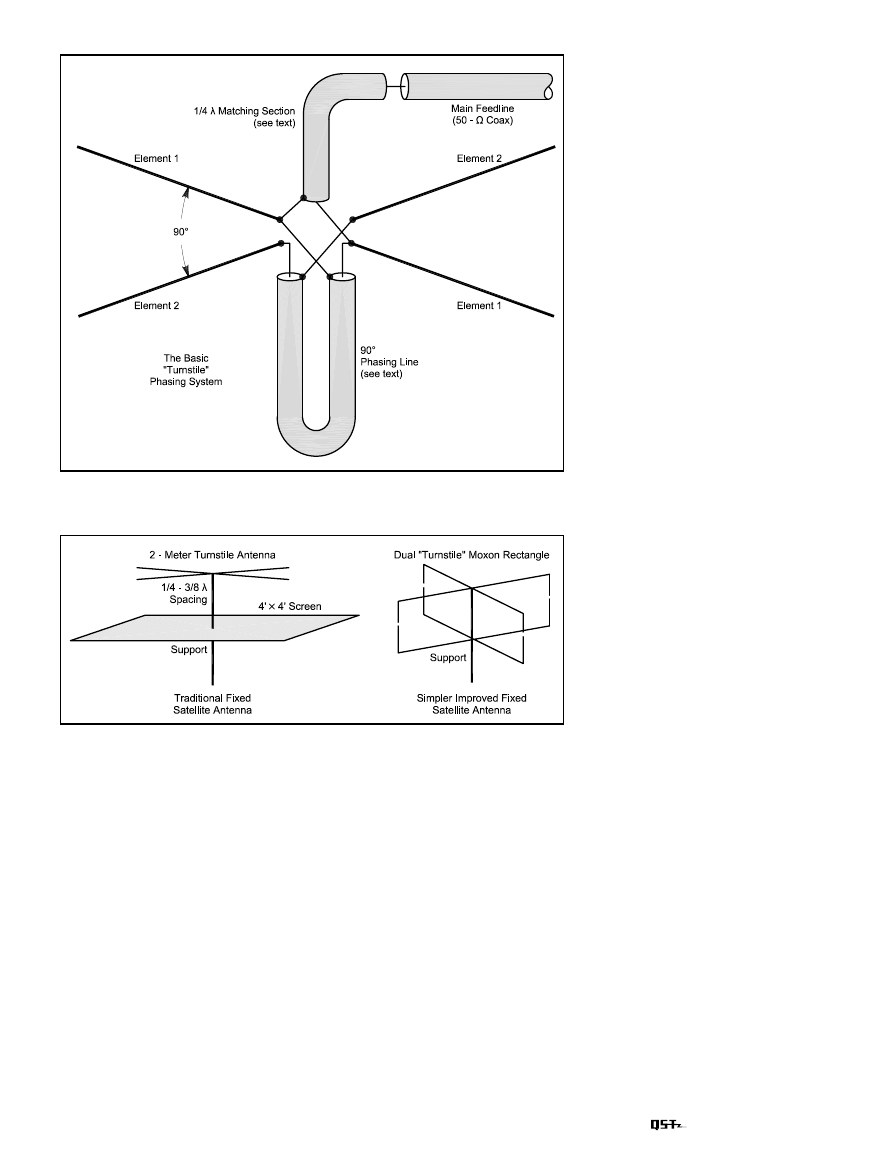
Figure 1 shows one general method of
obtaining the 90
°
phase shift that we need
for omnidirectional patterns. Note that
the coax center conductor connects to
only one of the two crossed elements. A
1
/
4
-
λ
section of transmission line that has
the same characteristic impedance as the
natural feed point impedance of the first
antenna element alone connects one ele-
ment to the next. The opposing ends of
the two elements go to the braid at each
end of the transmission line. If the ele-
ments happen to be dipoles, then a 70 to
75-
Ω
transmission line is ideal for the
phasing line. However, the resulting im-
pedance at the overall antenna feed point
A Simple Fixed Antenna for
VHF/UHF Satellite Work
Explore the low-Earth orbiting amateur satellites with
this effective antenna system.
will be exactly half the impedance of one
element alone. So we will obtain an im-
pedance of about 35
Ω
. For the dipole-
based turnstile antenna, we’ll either have
to accept an SWR of about 1.4:1 or we’ll
have to use a matching section to bring
the antenna to 50
Ω
. A parallel set of RG-
63
1
/
4
-
λ
lines will yield about 43
Ω
im-
pedance, about right to bring the 35-
Ω
antenna impedance to 50
Ω
for the main
coax feed line. For all such systems, we
must remember to account for the veloc-
ity factor of the transmission line, which
will yield a line length that is shorter than
a true quarter wavelength.
The dipole-based turnstile is popular
for fixed-position satellite work. Figure 2
shows—on the left—one recommended
system that has been in The ARRL An-
tenna Book since the 1970s. For 2 meters,
a standard dipole-turnstile sits over a
large screen that simulates ground. Spac-
ing the elements from the screen by
between
1
/
4
and
3
/
8
of a wavelength is rec-
ommended for the best pattern. For sat-
ellite operation, the object is to obtain as
close to a dome-like pattern overhead as
possible. The most desirable condition is
to have the dome extend as far down to-
ward the horizon as possible to let us
communicate with satellites as long as
possible during a pass.
The turnstile-and-screen system, while
simple, is fairly bulky and prone to wind
damage. However, the turnstile loses per-
formance if we omit the screen. One way
to reduce the bulk of our antenna is to
find an antenna with its own reflector.
However, it must have a good pattern for
the desired goal of a transmitting and re-
ceiving dome in the sky. The dual Moxon
rectangle array, shown in outline form on
the right of Figure 2, offers some advan-
tages over the traditional turnstile. First,
it yields a somewhat better dome-like
pattern. Second, it is relatively easy to
build and compact to install.
Almost every fixed satellite antenna
August 2001
39
Figure 1—The basic turnstile phasing (and matching) system for any antenna set
requiring a 90
°
phase shift between driven elements in proximity.
shows deep nulls at lower angles, and the
number of nulls increases as we raise the
antenna too high, thus defeating the de-
sire for communications when satellites
are at low angles. Figure 3 shows the el-
evation patterns of a turnstile-and-screen
and of a pair of Moxon rectangles when
both are 2
λ
above the ground. A 1
λ
height
will reduce the low angle ripples even
more, if that height is feasible. However,
the builder always has to balance the ef-
fects of height on the pattern against the
effects of ground clutter that may block
the horizon.
The elevation patterns show the con-
siderably smoother pattern dome of the
Moxon pair over the traditional turnstile.
The middle of the turnstile dome has
nearly 2 dB less gain than its peaks, while
the top valleys are nearly 3 dB lower than
Figure 2—Alternative schemes for fixed-position satellite antennas: the traditional
turnstile-and-screen and a pair of “turnstiled” Moxon rectangles.
the peaks. The peaks and valleys can make
the difference between successful commu-
nications and broken-up transmissions.
So, for the purpose of obtaining a good
dome, the Moxon pair may be superior.
A reasonable suggestion offered to me
was simply to add reflectors to a stan-
dard dipole turnstile and possibly obtain
the same freedom from a grid or screen
structure. Figure 4 shows the limitation
of that solution. The result of placing re-
flectors behind the dipole turnstile is a
pair of crossed 2-element Yagi beams fed
90
°
out of phase. The pattern is indeed
circular and stronger than that of the
Moxon pair. However, the beamwidth is
reduced to only 56
°
at the half-power
points. The antenna would make an ex-
cellent starter for a tracking AZ-EL rota-
tor system, but it does not have the
beamwidth for good fixed-position
service.
The Moxon pair, with lower but
smoother gain across the sky dome, of-
fers the fixed-antenna user the chance to
build a successful beginning satellite an-
tenna. The pattern will be circular within
under a 0.2-dB difference for 145.5 to
146.5 MHz, and within 0.5 dB for the en-
tire 2-meter band. Since satellite work is
concentrated in the 145.8 to 146.0 MHz
region, the broadbanded antenna will
prove fairly easy to build with success. A
435.6 MHz version, designed to cover the
435 to 436.2 MHz region of satellite ac-
tivity will have an even larger bandwidth.
Like the dipole-based turnstile, the
Moxons will be fed 90
°
out of phase with
a
1
/
4
-
λ
phasing line of 50-
Ω
coaxial cable.
The drivers will be connected just as
shown in Figure 1. Since the natural feed-
point impedance of a single Moxon rect-
angle of the design used here is 50
Ω
, the
pair will show a 25-
Ω
feed-point imped-
ance. Paralleled
1
/
4
-
λ
sections of 70- to
75-
Ω
coaxial cable will transform the low
impedance to a good match for the main
50-
Ω
coaxial line to the rig. In short, we
have “turnstiled” the Moxon rectangles
into a reasonable fixed-position satellite
antenna.
Building the Moxon Pairs
The Moxon rectangle is a modification
of the reflector-driver Yagi parasitic beam.
However, instead of using linear elements,
the driver and reflector are bent back to-
ward each other. The coupling between the
ends of the elements combined with the
coupling between parallel sections of the
elements combine to produce a pattern with
a broad beamwidth. By carefully selecting
the dimensions, we can obtain both good
performance (meaning adequate gain and
an excellent front-to-back ratio) and a
50-
Ω
feed point impedance.
1
In fact, a single Moxon rectangle
might be used on each band for reason-
ably adequate satellite service. When
pointed straight up, the Moxon rectangle
pattern is a very broad oval, although not
a circle. The oval pattern also gives the
Moxon another advantage over dipoles in
a turnstile configuration. If the phasing-
line between dipoles is not accurately cut,
the normal turnstile near-circle pattern
degrades into an oval fairly quickly be-
1
See “Having a Field Day with the Moxon Rect-
angle,”
QST, June, 2000, pp 38-42, for fur-
ther details on the operation of the Moxon
rectangle, along with the references in the
notes to that article. Also included in the
notes is the source for a program to calcu-
late the dimensions for a 50-
Ω
Moxon rect-
angle for any HF or VHF frequency using
only the design frequency and the element
diameter as inputs.

40
August 2001
Figure 4—A comparison of elevation patterns for 2-element
turnstiles (crossed 2-element Yagis, shown in blue) and a
Moxon pair (shown in red), both at 2
λ
height.
Figure 3—A comparison of elevation patterns for the turnstile-
and-screen system (with
3
/
8
λ
wavelength spacing, shown in
blue) and a Moxon pair (shown in red), both at 2
λ
height.
Table 1
Dimensions for Moxon Rectangles
for Satellite Use
Two are required for each antenna. The
phase-line is 50-
Ω
coaxial cable and the
matching line is parallel sections of 75-
Ω
coaxial cable. Low power cables less than
0.15 inches in outer diameter were used in
the prototypes. See Figure 5 for letter
references. All dimensions are in inches.
Dimension
145.9 MHz
435.6 MHz
A
29.05
9.72
B
3.81
1.25
C
1.40
0.49
D
5.59
1.88
E (B + C + D)
10.80
3.62
1
/
4
wavelength
20.22
6.77
0.66 velocity factor
phasing and
matching lines
13.35
4.47
Figure 5—The basic dimensions of a Moxon rectangle. Two identical rectangles are
required for each “turnstiled” pair.
cause the initial single dipole pattern is a
figure
8
. The single Moxon oval pattern
allows both dimensional inaccuracies and
phasing-line inaccuracies of considerable
amounts before degrading from a nearly
perfect circle.
Figure 5 shows the critical dimensions
for a Moxon rectangle. The lettered ref-
erences are keys to the dimensions in
Table 1. The design frequencies for the
two satellite antenna pairs are 145.9 MHz
and 435.5 MHz, the centers of the satel-
lite activity on these two bands. The
2-meter Moxon prototype uses
3
/
16
-inch
diameter rod, while the 435 MHz version
uses #12 AWG wire with a nominal
0.0808-inch diameter. (Single Moxons
built to these dimensions would cover all
of 2-meters and about 12 MHz of the
432 MHz band.) Going one small step
up or down in element diameter will still
produce a usable antenna, but major
diameter changes will require that the
dimensions be recalculated.
The reflectors are constructed from a
single piece of wire or rod. I use a small
tubing bender to create the corners. The
rounding of the corners creates a slight
excess of wire for the overall dimensions
in the table. I normally arrange the curve
so that the excess is split between the side-
to-side dimension (A) and the reflector tail
(D). Practicing on some scrap house wire
may make the task go well the first time
with the actual aluminum rod. The total
reflector length should be A + (2
×
D).
The driver consists of two pieces,
since we’ll split the element at its center
for the feeding and phasing system. I usu-
ally make the pieces a bit longer before
bending and trim them to size afterwards.
The total length of the driver, including
the open area for connections, should be
A + (2
×
B).
Perhaps the most critical dimension is
August 2001
41
the gap, C. I have found nylon tubing,
available at hardware depots, to be very
good to keep the rod ends aligned and
correctly spaced. When everything has
been tested and found correct, a little su-
per-glue on the tubing ends and aluminum
stands up to a lot of wind. I usually nick
the aluminum just a little to let the glue
settle in and lock the junction. For the
UHF version, a short length of heat-shrink
tubing provides a lock for the size of the
gap and the alignment of the element tails.
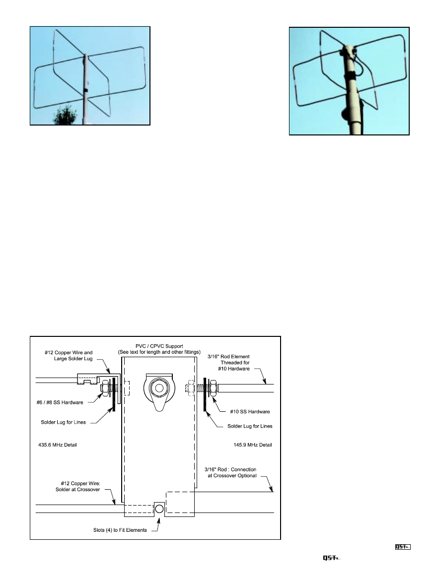
It is one thing to make a single Moxon
and another to make a working crossed
pair. Figure 6 shows the general scheme
that I used for the prototypes, using
CPVC. (Standard schedule 40 or thinner
PVC or fiberglass tubing can also be used.)
The support stock is
3
/
4
inch nominal. The
reflectors go into slots at the bottom of
the tube and are locked in two ways.
A close-up view of the 145.9 MHz
rectangle pair.
The 435-MHz Moxons.
Figure 6—Some construction details for the Moxon pairs constructed as prototypes.
Whether or not the two reflectors make
contact at their center points makes no
difference to performance, so I ran a very
small sheet screw through both 2-meter
reflectors to keep their relative positions
firm. I soldered the centers of the 435-
MHz reflectors. Then I added a coupling
to the bottom of the CPVC to support the
double reflector assembly and to connect
the boom to a support mast. Cementing or
pressure fitting the cap is a user option.
The feed point assemblies are attached
to solder lugs. The phasing line is routed
down one side of the support, while the
matching section line is run down the
other. Electrical tape holds them in place.
For worse weather, the tape may be over-
sealed with butylate or other coatings.
Likewise, the exposed ends of the coax
sections and the contacts themselves
should be sealed from the weather.
The details can be seen—as built for the
experimental prototypes in one of the
photos—before sealing, since lumps of
butylate or other coatings tend to obscure
interesting details.
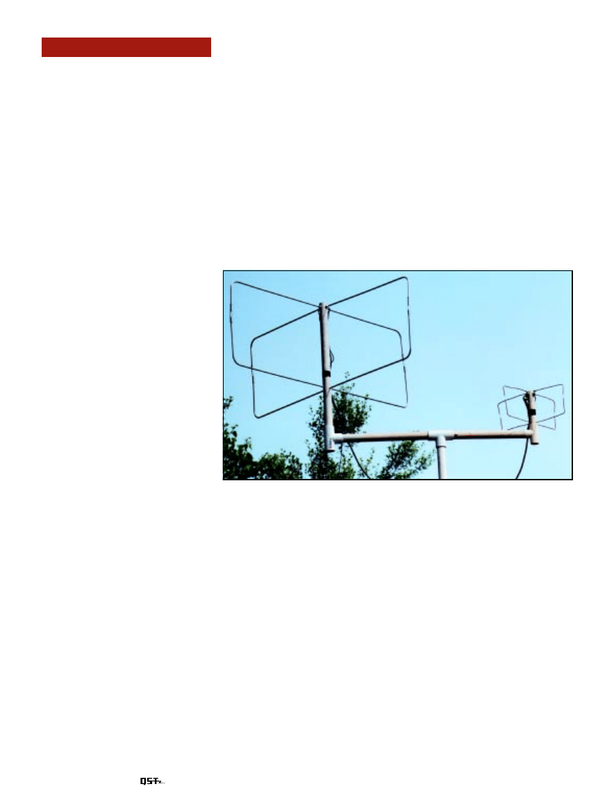
The overall assembly of the two anten-
nas appears in the second photograph. The
PVC from the support Ts can go to a cen-
ter Tee that also holds the main support
for the two antennas. A series of adapt-
ers, made from miscellaneous PVC parts
to fit over a standard length of TV mast.
Alternatively, the antennas can be sepa-
rately mounted about 10 feet apart. The
10-foot height of the assembly has proven
adequate for general satellite reception,
although I live almost at the peak of a hill.
The antennas can be mounted on the
same mast. However, for similar sky-dome
patterns, they should each be the same
number of wavelengths above ground. For
example, if the 2-meter antenna is about
two wavelengths up at about 14 feet or so,
then the bottom of the 435-MHz antenna
should be only about 4.5 feet above the
ground. Placing the higher-frequency an-
tenna below the 2-meter assembly will
create some small irregularities in the de-
sired dome pattern, but not serious enough
to affect general operation.
There is no useful adjustment to these
antennas except for making the gap be-
tween the drivers and reflectors as accu-
rate as possible. Turnstile antennas show
a very broad SWR curve. Across 2 meters,
for example, the highest SWR is under
1.1:1. However, serious errors in the phas-
ing line length can result in distortions to
the desired circular pattern. There is no
substitute for checking the lengths of the
phasing line and the matching section
several times before cutting. The correct
length is from one junction to the next,
including the portions of exposed cable
interior.
These two little antennas will not com-
pete with tracking AZ-EL rotating systems
for horizon-to-horizon satellite activity.
For satellite work, however, power is not
always the problem (except for using too
much) and modern receiver front-ends
have enough sensitivity to make commu-
nication easy. So when the satellite
reaches an angle of about 30
°
above the
horizon, these antennas will give a very
reasonable account of themselves. When
you become so addicted to satellite com-
munication that you invest in the complete
tracking system, these antennas can be
used as back-ups while parts of the com-
plex system are down for maintenance!
You can contact the author at 1434 High
Mesa Dr, Knoxville, TN 37938; cebik@
cebik.com.
Wyszukiwarka
Podobne podstrony:
23 299 318 Optimizing Microstructure for High Toughness Cold Work Steels
Anteny VHF i UHF Świat Radio Czerwiec 2009(1)
23 299 318 Optimizing Microstructure for High Toughness Cold Work Steels
NACA TM 948 A Simple Approximation Method for Obtaining the Spanwise Lift Distribution
The Best Small Antennas For MW, LW, And SW rev 2
Herbs for First Aid Simple Home Remedies for Minor Ailments and Injuries
VHF i UHF Morskie
Anteny VHF i UHF Świat Radio Czerwiec 2009
PL HF bandplan VHF UHF v0 1
Radio Shack PRO 28 VHF UHF Scanner Reciever Manual
Robert Krausz W d Gann Treasure Discovered Simple Trading Plans For Stocks & Commodities(pdf)
7 SIMPLE HOME REMEDIES FOR A STUFFY NOSE
03 MEMS Technology for Optical Crosslink for Micro Nano Satellites
Stoerausblendung mit zwei Antennen Gegen Gleichkanalstoerungen auf VHF und UHF
Kto,blokuje tą wiedzę Antenna To Replace?tteries And Provide Unlimited Free Energy For Electric?rs
2 17 26 Hot Work Steels with Improved Properties for Die Casting
więcej podobnych podstron