USB pinout and signals @ pinouts.ru
http://pinouts.ru/Slots/USB_pinout.shtml
1 z 5
2007-09-20 22:08
USB pinout
bus or interface
bookmark this page
USB (Universal Serial Bus) designed to connect peripherals such as mice, keyboards, scanners,
digital cameras, printers, hard disks, and networking components to PC. It becames standard
connection method for scanners, digital cameras and for some printers.
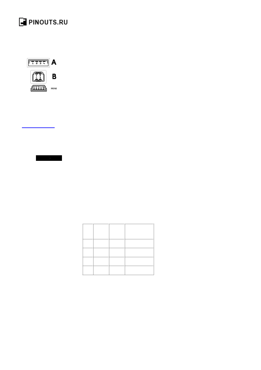
4 pin USB A or USB B
plug connector
at the peripherals
The Universal Serial Bus is host controlled and
there can be only one host per bus. An USB
system consist of a host controller and multiple
devices connected in a tree-like fashion using
special hub devices. Hubs may be cascaded, up
to 5 levels. Up to 127 devices may be
connected to a single host controller. USB
interface aimed to remove the need for adding
expansion cards into the computer's PCI or
PCI-E bus, and improve plug-and-play
capabilities by allowing devices to be hot
swapped or added to the system without
rebooting the computer. When the new device
first plugs in, the host enumerates it and loads
the device driver necessary to run it. The
loading of the appropriate driver is done using
a PID/VID (Product ID/Vendor ID)
combination supplied by attached hardware.
The USB host controllers has their own
specifications: UHCI (Universal Host
Controller Interface) and OHCI (Open Host
Controller Interface) are used with USB 1.1,
EHCI (Enhanced Host Controller Interface) is
used with USB 2.0
Pin Name
Cable
color
Description
1
VCC
Red
+5 VDC
2
D-
White Data -
3
D+
Green Data +
4
GND Black Ground
Pin x of mini-USB connector may be not
connected, connected to GND or used as
attachment identification at some portable
devices.
USB pinout signals
USB is a serial bus. It uses 4 shielded wires:
two for power (+5v & GND) and two for
differential data signals (labelled as D+ and D-
in pinout). NRZI (Non Return to Zero Invert)
Load Pin Solutions
Standard Models and
Custom Versions
Specification Worksheet
Available
www.sentranllc.com

USB pinout and signals @ pinouts.ru
http://pinouts.ru/Slots/USB_pinout.shtml
2 z 5
2007-09-20 22:08
encoding scheme used to send data with a sync
field to synchronise the host and receiver
clocks. In USB data cable Data+ and Data-
signals are transmitted on a twisted pair. No
termination needed. Half-duplex differential
signaling helps to combat the effects of
electromagnetic noise on longer lines. Contrary
to popular belief, D+ and D- operate together;
they are not separate simplex connections.
USB transfer modes
Univeral serial bus supports Control, Interrupt,
Bulk and Isochronous transfer modes.
USB transfer rates: Low Speed, Full
Speed, Hi-speed.
USB supports three data rates: Low Speed (1.5
Mbit per second) that is mostly used for
Human Input Devices (HID) such as
keyboards, mice, joysticks and often the
buttons on higher speed devices such as
printers or scanners; Full Speed (12 Mbit per
second) which is widely supported by USB
hubs, assumes that devices divide the USB
bandwidth between them in a first-come
first-serve basis - it"s easy to run out of
bandwidth with several devices; Hi-Speed (480
Mbit per second) was added in USB 2.0
specification. Not all USB 2.0 devices are
Hi-Speed. A USB device must indicate its
speed by pulling either the D+ or D- line high
to 3.3 volts. These pull up resistors at the
device end will also be used by the host or hub
to detect the presence of a device connected to
its port. Without a pull up resistor, USB
assumes there is nothing connected to the bus.
In order to help user to identify maximum
speed of device, USB device often specify it's
speed on it's cover with one of USB special
marketing logos.
USB Hi-speed devices
Hi-Speed devices should fall back to the
slower data rate of Full Speed when plugged
into a Full Speed hub. Hi-Speed hubs have a
special function called the Transaction
Translator that segregates Full Speed and Low
Speed bus traffic from Hi-Speed traffic.
Ads by Google
USB Hub Review
Firewire USB
USB Card
USB Ports

USB pinout and signals @ pinouts.ru
http://pinouts.ru/Slots/USB_pinout.shtml
3 z 5
2007-09-20 22:08
USB powered devices
The USB connector provides a single 5 volt
wire from which connected USB devices may
power themselves. A given segment of the bus
is specified to deliver up to 500 mA. This is
often enough to power several devices,
although this budget must be shared among all
devices downstream of an unpowered hub. A
bus-powered device may use as much of that
power as allowed by the port it is plugged into.
Bus-powered hubs can continue to distribute
the bus provided power to connected devices
but the USB specification only allows for a
single level of bus-powered devices from a
bus-powered hub. This disallows connection of
a bus-powered hub to another bus-powered
hub. Many hubs include external power
supplies which will power devices connected
through them without taking power from the
bus. Devices that need more than 500 mA or
higher than 5 volts must provide their own
power. When USB devices (including hubs)
are first connected they are interrogated by the
host controller, which enquires of each their
maximum power requirements. However,
seems that any load connected to USB port
may be treated by operating system as device.
The host operating system typically keeps track
of the power requirements of the USB network
and may warn the computer's operator when a
given segment requires more power than is
available and may shut down devices in order
to keep power consumption within the
available resource.
USB power usage:
Bus-powered hubs: Draw Max 100 mA at
power up and 500 mA normally.
Self-powered hubs: Draw Max 100 mA, must
supply 500 mA to each port.
Low power, bus-powered functions: Draw
Max 100 mA.
High power, bus-powered functions:
Self-powered hubs: Draw Max 100 mA, must
supply 500 mA to each port.
Self-powered functions: Draw Max 100 mA.
Suspended device: Max 0.5 mA

USB pinout and signals @ pinouts.ru
http://pinouts.ru/Slots/USB_pinout.shtml
4 z 5
2007-09-20 22:08
USB voltage:
Supplied voltage by a host or a powered hub
ports is between 4.75 V and 5.25 V. Maximum
voltage drop for bus-powered hubs is 0.35 V
from it's host or hub to the hubs output port.
All hubs and functions must be able to send
configuration data at 4.4 V, but only
low-power functions need to be working at this
voltage. Normal operational voltage for
functions is minimum 4.75 V.
USB cable shielding:
Shield should only be connected to Ground at
the host. No device should connect Shield to
Ground.
USB cable wires:
Shielded:
Data: 28
AWG
twisted
Power: 28
AWG
- 20
AWG
non-twisted
Non-shielded:
Data: 28
AWG
non-twisted
Power: 28
AWG
- 20
AWG
non-twisted
Power Gauge Max length
28
0.81 m
26
1.31 m
24
2.08 m
22
3.33 m
20
5.00 m
Related Links:
USB cable schematic
mini-USB connector pinout
Pinouts.ru
>
Buses and slots connectors pinouts
> Pinout of USB and layout of
4 pin USB A or USB B plug connector and 4 pin USB A / USB B / mini-USB
jack connector
Document status:
correct
Source(s) of this and additional information:
USB FAQ
at
USB Implementers Forum
USB Specification v1.0 at
USB Implementers Forum
,
wikipedia.org
, "USB in a Nutshell"
59 reports

USB pinout and signals @ pinouts.ru
http://pinouts.ru/Slots/USB_pinout.shtml
5 z 5
2007-09-20 22:08
Last updated at Wed Aug 22 2007.
Submit additions or corrections
for this
document.
Is this document
correct
or
incorrect
? What is your opinion?
[
Discuss at the forum
] [
Back to index
] [
SUBMIT new pinout
]
This page contain parts under Copyright © 2000-2007 by
pinouts.ru
team.
No any portion of this webpage may be reproduced in any form without visible direct link to this page provided.
Webmaster permission
required in any other cases.
Efforts have been made to ensure this page is correct, but it is the responsibility of the user to verify the data is correct for their application.
365354 hits since March 4, 2005
Wyszukiwarka
Podobne podstrony:
ADB DVB T USB Stick, opis instalacji
Przekrój poziomy csn oznaczenia opis
Programator na USB (USBasp), PRUSB Opis l
Instrukcja-2-instalaja prztwornika USB, Opis instalacji programu:
DEFA opis i oznaczenia katalogowe
Opis wyprowadzeń w wtyczkach, Elektronika
Oznaczniki kabel lhs1
Programator na USB (USBasp), PRUSB Opis
OPIS MONTAZU KABELKA USB
Opis koncentratora USB
Oznaczniki kabel lhs2
Programator na USB (USBasp), PRUSB Opis l
kabel opis
PC GamePort i wtyczka opis
oznaczenie przewodów elektrycznych (opis symboli )
wtyczka do radia kia opis z natury
więcej podobnych podstron