
Technical Bulletin
C
1999 Volkswagen of America, Inc.
Subject:
Model(s):
Group:
Number:
Date:
Anti-theft Immobilizer On Board Diagnostic (OBD)
2000
01
99–11
June 25, 1999
Golf, Jetta, Cabrio, New Beetle
The anti-theft immobilizer information in this
Technical Bulletin will be integrated into the
Repair Manual (Volkswagen Electronic
Service and Information System) on CD-ROM
at the next update.
Contents
Subject
Technical
Bulletin Page
Repair
Manual Page
Anti-theft immobilizer On Board Diagnostic (OBD)
1
–
– Immobilizer electronic components and warning light function
1
–
– Immobilizer On Board Diagnostic, initiating
3
–
– Diagnostic Trouble Code (DTC) table
12
–
– Read measured value block
16
–
– Matching ignition keys
19
–
– Lost key procedure
25
–
– Procedure after changing instrument cluster (Matching)
26
–
– Procedure after changing engine control module (Matching)
27
–
– Replacement instrument cluster, adaptation
29
–
– Immobilizer troubleshooting
31
–
– Emergency start function, activating without VAG 1551
34
–

1
Anti-theft immobilizer On Board
Diagnostic (OBD)
Immobilizer electronic components and
warning light function
The immobilizer electronics consist of:
♦
control electronics in instrument cluster
♦
a warning light for anti-theft immobilizer sensor -K117- in instru-
ment cluster (speedometer display)
♦
a matched engine control module
♦
an induction coil on the ignition lock
♦
matched ignition keys with electronic components (transponder
and response reader memory)
Malfunction recognition and Diagnostic Trouble Code
(DTC) display via warning light for anti-theft
immobilizer sensor
An intact immobilizer system is indicated by the warning light for
anti-theft immobilizer sensor -K117- lighting up and going out after
approx. 3 seconds when the ignition is switched on.

2
Warning light flashes or stays lit when the ignition is
switched on (indicates a malfunction in system) if:
♦
the ignition key has been carried out incorrectly.
♦
no transponder (response reader memory) is present in the
ignition key.
♦
An unauthorized ignition key is used.
♦
an unauthorized engine control module is detected.
♦
a malfunction is present in the induction coil of anti-theft immo-
bilizer -D2-.
♦
a malfunction is present in the data wiring.
Warning light does not light up when the ignition is
switched on if:
♦
the immobilizer control module has detected an authorized
key.
♦
the immobilizer control module has not detected an incorrect
engine control module.
♦
the immobilizer control module is currently “matching keys”
and after matching the keys no malfunction has occurred.
To troubleshoot, perform the On Board Diagnostic (OBD) program
and retrieve the stored information with either the VAG 1551/1552
Scan Tool or VAS 5051 Vehicle Diagnostic, Testing and Information
System.

3
Immobilizer On Board Diagnostic (OBD),
initiating
If malfunctions occur in the sensors and components being moni-
tored, they will be stored in the Diagnostic Trouble Code (DTC)
memory together with an indication of the type of malfunction.
A maximum of 4 DTCs can be stored simultaneously.
Sporadic malfunctions are automatically cancelled if they are not re-
peated in next 50 engine starts.
OBD must be initiated at the commencement of troubleshooting
and the stored information checked with the VAG 1551/1552 Scan
Tool or VAS 5051 Vehicle Diagnostic, Testing and Information Sys-
tem.
Note:
The following description deals only with the VAG 1551Scan Tool.
The information displayed is used in conjunction with a DTC table
which has information on the possible causes for pin-pointed repair
steps.
4
Connecting VAG 1551 Scan Tool and selecting
functions (Checking control module version)
Checking requirements:
♦
All fuses OK according to wiring diagram
♦
Supply voltage OK (at least 9.0 V).
Connect VAG 1551 using cable VAG 1551/3 as follows:
– Locate Data Link Connector (DLC) under instrument panel.
– Connect cable VAG 1551/3 to DLC
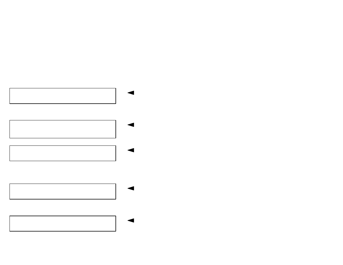
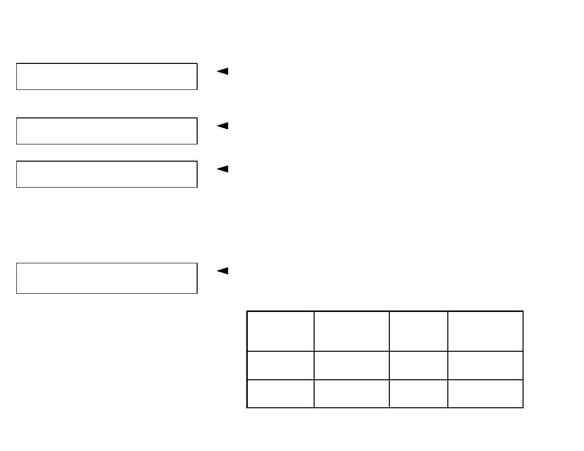
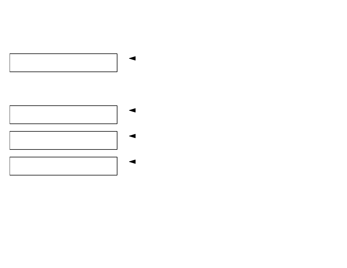
Indicated on display
* Appears alternately
VAG - ON BOARD DIAGNOSTIC
HELP
1 - Rapid data transfer*
2 - Blink code output*
5
Note:
♦
If the display remains blank, check the VAG 1551 voltage supply
according to the wiring diagram.
⇒
Electrical Wiring Diagrams, Troubleshooting and Component
Locations binder
♦
Additional operating instructions can be called up with the scan
tool -HELP- button.
♦
The
→
button advances the program sequence.
♦
In the operating mode 1 “Rapid data transfer” the function 00
“Automatic test sequence” can be carried out. All vehicle control
modules will be checked automatically.
– Switch ignition on.
– Switch printer on with Print button (indicator lamp in button lights
up).
– Press button -1- for “Rapid data transfer” mode.
Indicated on display
– Press buttons -1- and -7- to select “Instrument Cluster” address
word 17.
– Confirm entry with -Q- button.
Indicated on display
– Press
→
button.
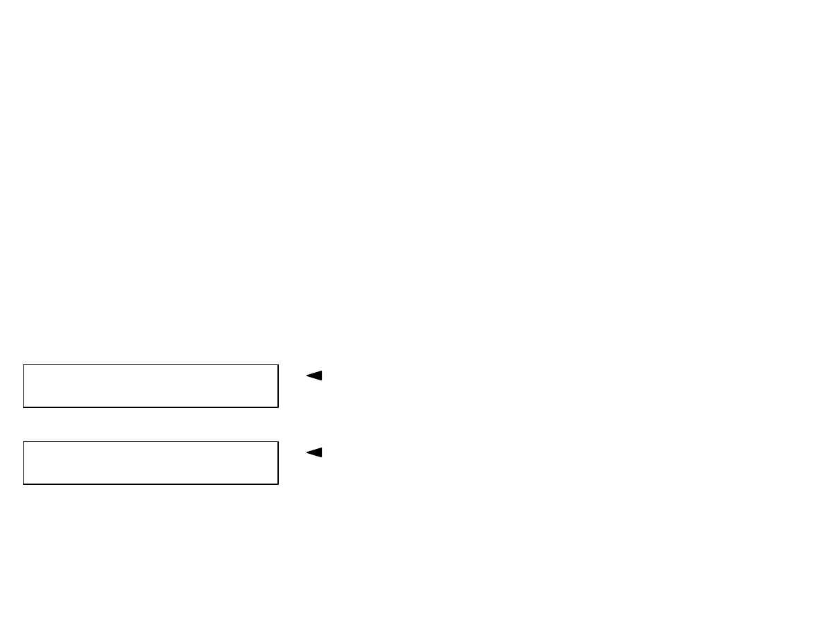
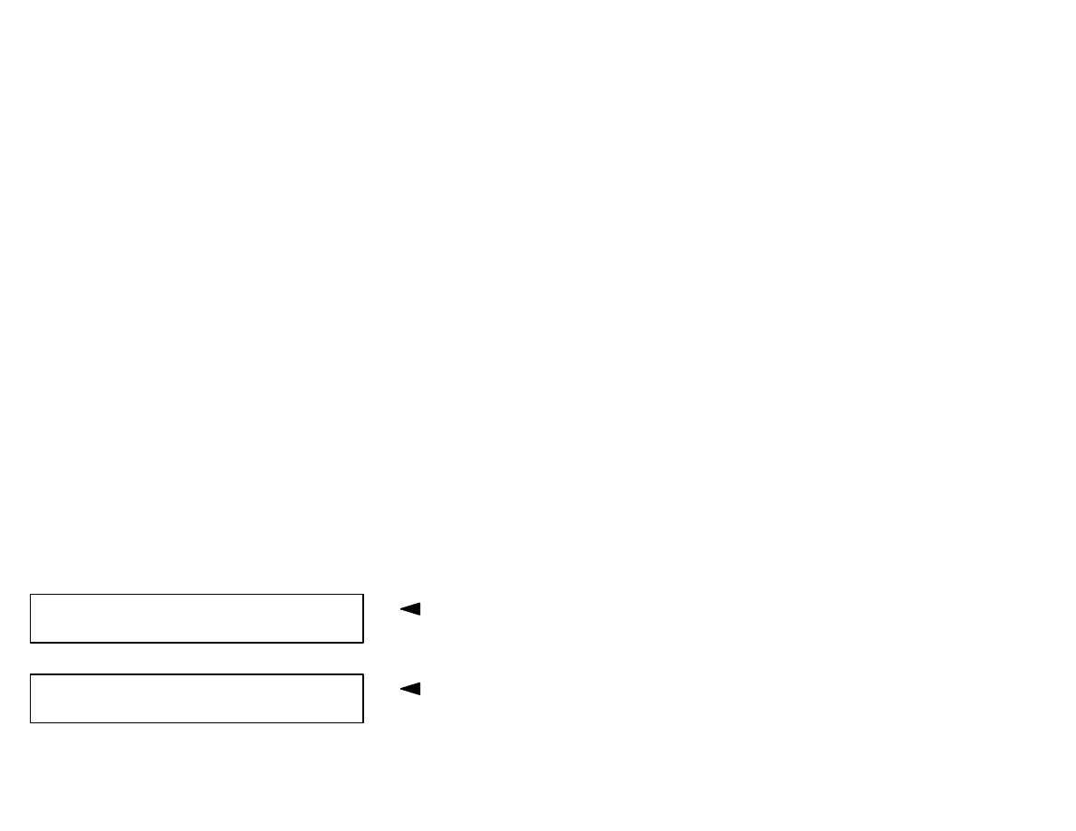
Indicated on display
Rapid data transfer
HELP
Input address word XX
1J0919860D A4-COMBI INSTR.VDO V04
→
Coding 00042 WSC 00000
IMMO–IDENT No.: VWZ7Z0V0066808
→
6
Immobilizer identification number (14 character, VW...)
– Press
→
button.
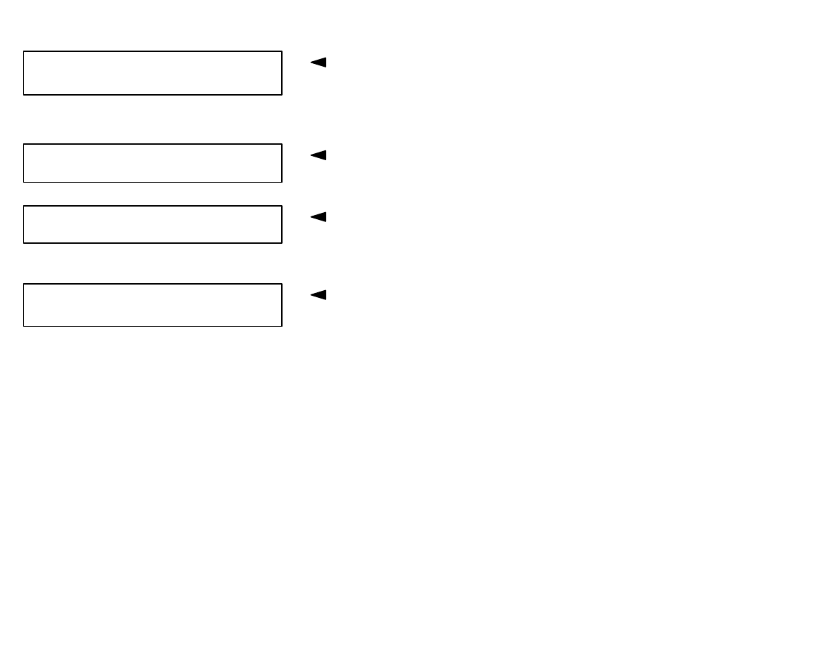
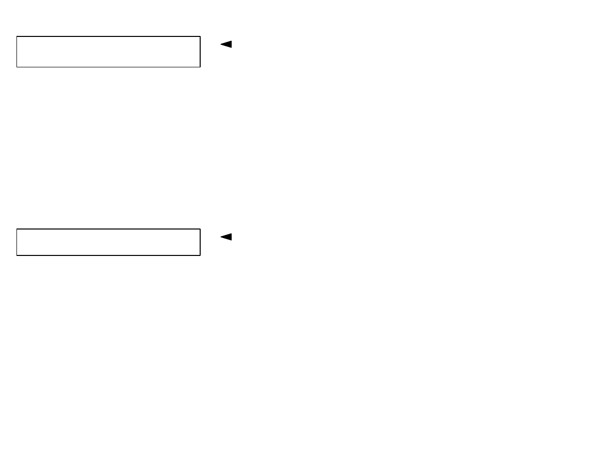
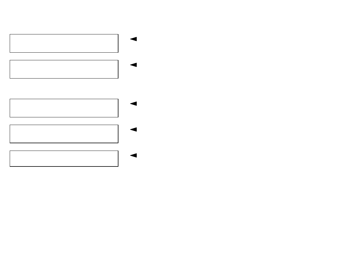
Indicated on display
Indicated on display
By pressing the -HELP- button a list of possible malfunction causes
is printed out.
– After correcting malfunctions, enter address word 17 again for in-
strument cluster and confirm with -Q- button.
Indicated on display
– Press
→
button.
Indicated on display
If the -HELP- button is pressed, a list of selectable functions is
printed out.
Rapid data transfer
HELP
Select function XX
Control module does not answer!
HELP
IMMO–IDENT No.: VWZ7Z0V0066808
→
Rapid data transfer
HELP
Select function XX
7
List of selectable functions
Page
02 -
Check DTC memory
8
05 -
Erase DTC memory
9
06 -
End output
11
08 -
Read measured value block
16
10 -
Adaptation
19
11 -
Login procedure
20
Note:
♦
Do not select further functions other than those listed above
(which can be printed out after pressing the -HELP- button).
♦
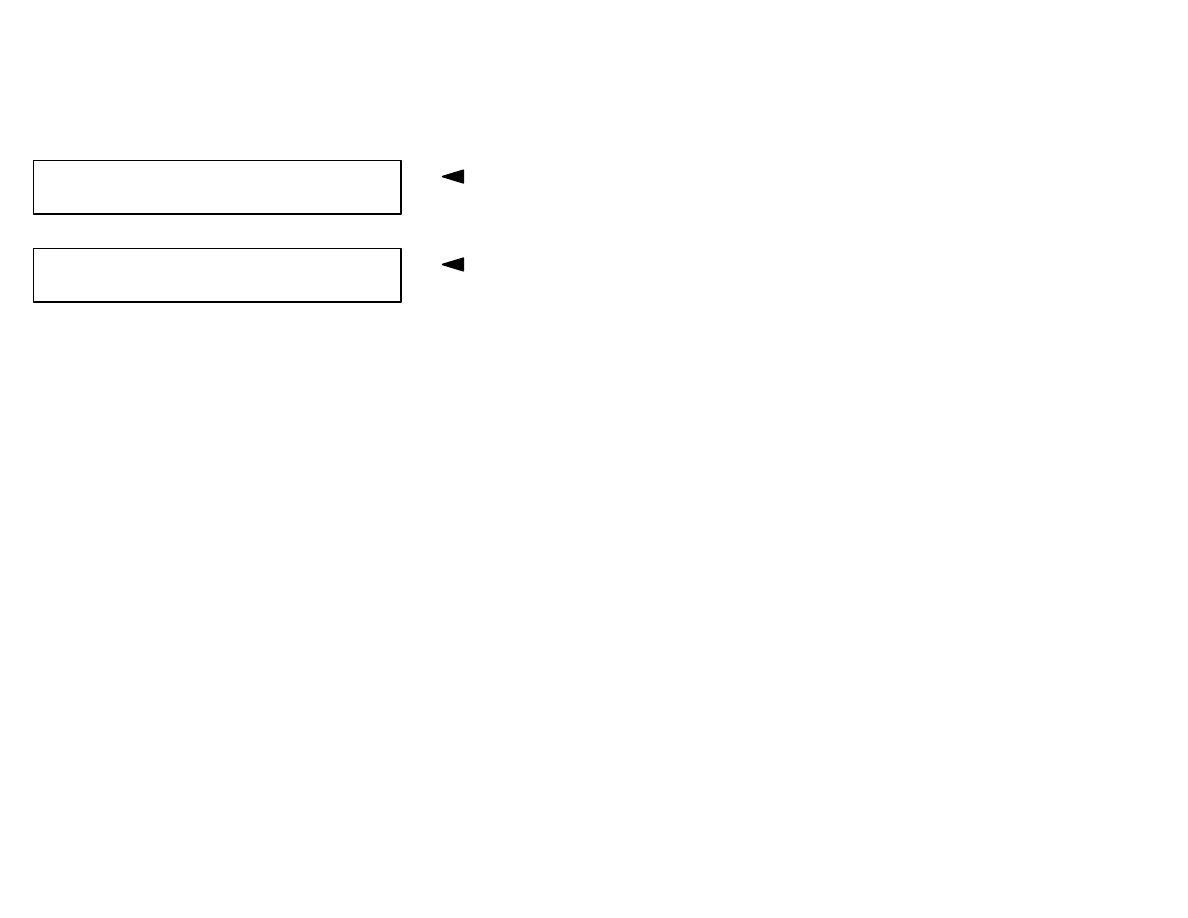
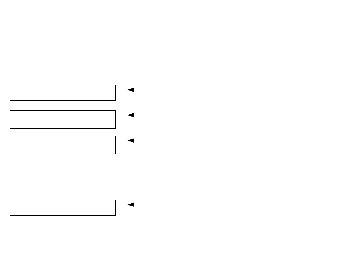
After the function is completed the VAG 1551 returns to the fol-
lowing start position:
Indicated on display
Rapid data transfer
HELP
Select function XX
8
Checking DTC memory
Note:
The displayed DTC information is not constantly up-dated, but is
only restarted when initiating the On Board Diagnostic (OBD) or
with function 05 “Erase DTC memory”.
– Switch printer on with -Print- button (indicator lamp in button
lights up).
Indicated on display
– Press buttons -0- and -2- to select “Check DTC memory” function
02.
Indicated on display
– Confirm entry with -Q- button.
The number of stored DTCs appears in the display.
The stored DTCs are displayed and printed out one after another.
– Locate DTC printed out in DTC table and correct
⇒
Page 12.
If “No DTC recognized” is displayed the program will return to the
starting point after pressing the
→
button.
Indicated on display
If display reads otherwise:
⇒
Scan tool operating instructions
Rapid data transfer
HELP
Select function XX
Rapid data transfer
Q
02 – Check DTC memory
X DTCs recognized!
No DTC recognized!
→
Rapid data transfer
HELP
Select function XX
9
– Press buttons -0- and -6- to select “End output” function 06
⇒
Page 11
– Switch ignition off and separate DLC.
Erasing DTC memory
Note:
After erasing the DTC memory its contents will automatically be in-
dicated. If the DTC memory cannot be erased, again check the
DTC memory and repair malfunctions.
Requirements
♦
DTC memory has been checked
⇒
Page 8
♦
All malfunctions repaired.
After the DTC memory has been successfully checked:
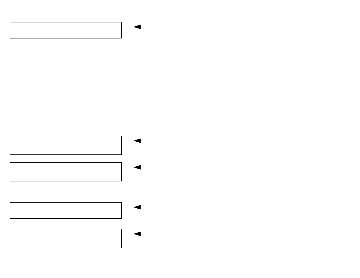
Indicated on display
– Press buttons -0- and -5- to select “Erase DTC memory” function
05.
Indicated on display
– Confirm entry with -Q- button.
Rapid data transfer
HELP
Select function XX
Rapid data transfer
Q
05 – Erase DTC memory
10
Indicated on display
The Diagnostic Trouble Code (DTC) memory is now erased.
– Press
→
button.
Indicated on display
If this appears in the display, the test sequence is faulty.
If this appears in the display, the test sequence is faulty.
Note:
Adhere exactly to the test sequence: First check the Diagnostic
Trouble Code (DTC) memory and, if necessary, repair any malfunc-
tions.
Rapid data transfer
→
DTC memory is erased!
Rapid data transfer
HELP
Select function XX
Warning!
DTC memory was not checked
Rapid data transfer
→
DTC memory was not checked
11
Ending output
– Press buttons -0- and -6- to select “End output” function 06.
Indicated on display
– Confirm entry with -Q- button.
Indicated on display
– Switch ignition off.
– Disconnect VAG 1551 Scan tool.
Rapid data transfer
Q
06 – End output
Rapid data transfer
Help
Enter address word XX

12
Diagnostic Trouble Code (DTC) table
CAUTION!
After repairs the DTC memory of the engine control module must always be checked and the DTC
memory content “Engine control module blocked” erased. Check and eliminate any further mal-
functions stored.
Note:
♦
All static and sporadic malfunctions are stored in the DTC memory: A malfunction is recognized as a static malfunc-
tion when it is present for a minimum of 2 seconds. If the malfunction is no longer present after this time, it is stored
as a sporadic fault and “/SP” appears on the display.
♦
After switching on the ignition, malfunctions stored are first recognized as sporadic and are changed to static if they
are present after the check has been completed.
♦
If a sporadic malfunction is no longer present during the next 50 driving cycles (ignition on for a minimum of 2 sec-
onds) it is erased.
♦
The following table lists all the malfunctions, with the corresponding 5-digit code numbers, that can be recognized
by the immobilizer control module and printed out by the VAG 1551.
♦
DTCs appear only on a print-out.
♦
Before replacing a component shown as faulty, check wiring and connections to the component as well as Ground
connections according to the wiring diagram.
♦
When the repair has been completed, the DTC memory must always be checked again with the VAG 1551 and then
erased.

13
VAG 1551 print out
Possible cause
Possible effects
Correction
01128
Induction coil of anti-theft
Immobilizer sensor
Wiring from induction coil
to instrument cluster faulty
or
Induction coil faulty
Engine will not start and
warning light flashes
– Check induction coil wire
and wire routing (visual
check), replace coil if
necessary.
– Erase DTC memory and
check again (
⇒
Page 9
and Page 8), replace in-
strument cluster if nec-
essary.

14
VAG 1551 print out
Possible cause
Possible effects
Correction
01176
Key
Signal too low
not authorized
Induction coil or wire faulty
(transfer resistance/loose
contact)
or
Ignition key electronics
(transponder) missing or
not functioning
or
Mechanically correct igni-
tion key not matched
Engine will not start and
warning light flashes
Engine will not start and
warning light flashes
Engine will not start and
warning light flashes
– Check induction coil wire
and wire routing (visual
check), replace coil if
necessary.
– Replace ignition key and
rematch all ignition keys
and check function
⇒
Page 19.
– Rematch all ignition keys
and check function
⇒
Page 19.
01177
Engine control module not
authorized
Engine control module not
matched.
W-wire between the con-
trol modules is OK.
Engine will not start and
warning light flashes
– Match engine control
module
⇒
Page 27.

15
VAG 1551 print out
Possible cause
Possible effects
Correction
01179
Key programming incorrect Ignition key matching faulty Warning light flashes quick-
ly
– Rematch all ignition keys
by entering the secret
number and check func-
tion
⇒
Page 19.
65535
Control module faulty
Instrument cluster control
module faulty
Engine will not start and
warning light lights up
– Replace instrument clus-
ter
Other DTCs
If DTCs are displayed that are not shown in this table,
⇒
OBD of instrument cluster
16
Read measured value block
Indicated on display:
– Press buttons -0- and -8- to select “Read measured value block”
function 08.
Indicated on display
– Confirm entry with -Q- button.
Indicated on display
– Press buttons -0-, -2 and -2-.
– Confirm entry with -Q- button.
Note:
When the printer is switched on the actual display is printed out.
– Indicated on display, for example
Evaluating measured value block
Authorized
start?
Engine control
module an-
swers?
Key condi-
tion OK?
No. of
matched keys
1
yes
1
yes
1
yes
2
0
no
0
no
0
no
Rapid data transfer
HELP
Select function XX
Rapid data transfer
Q
08 – Read measured value block
Read measured value block
Input display group number XX
Read measured value block 22
→
1 1 1 2

17
Evaluating malfunctions:
♦
Start authorized: “0”:
A non-coded or incorrectly coded key has been used or the en-
gine control module has an incorrect code or a malfunction
⇒
check engine control module DTC memory.
♦
Engine control module answers: “0”:
There is a malfunction in the engine control module or in wiring
⇒
Check engine control module DTC memory.
♦
Key condition OK: “0”:
♦
A faulty key or a key without transponder has been used
♦
An ignition key with an incorrect type of transponder was used
(fixed code transponder)
♦
Induction coil malfunction
– Check DTC memory (function 02).
♦
Number of matched keys: 2
If the value displayed in the first 3 display fields is 1:
– Press button -3-.
18
– Indicated on display, for example
If something different appears on the display, the “Matching of
keys” function must be performed,
⇒
Page 19.
If a “0” is displayed in display field 3:
An ignition key with an incorrect type of transponder was used.
– Obtain a key with correct type of transponder.
Note:
There are various types of ignition keys with various types of trans-
ponders. Observe when ordering parts!
– Press
→
button.
Indicated on display
Read measured value block 23
→
1 0 1
Rapid data transfer
HELP
Select function XX

19
Matching ignition keys
Note:
♦
If new or additional ignition keys are required they must be
matched to the immobilizer control module.
♦
Note the procedure when changing the locking set and the im-
mobilizer control module.
♦
The matching procedure must always be carried out for all the
ignition keys, including the existing ones.
♦
The number of keys already matched will be displayed when the
adaptation (matching) function is selected.
♦
If only one key is matched, the vehicle can be started immediate-
ly with this key. If more than one key has been matched, the ve-
hicle can only be started immediately with the last key matched.
♦
The matching procedure can be interrupted by pressing the -C-
button on the VAG 1551.
CAUTION!
The VAG 1551 dealership number (workshop code)
will be stored in the immobilizer control module when
matching ignition keys.
Requirements
♦
All ignition keys available. If no old ignition key is available see
“Lost key procedure”,
⇒
Page 25
♦
Key fob with covered secret number is available, if not see “Es-
tablishing secret number”,
⇒
Page 25
20
– Insert correct profile ignition key in ignition lock.
– Connect VAG 1551, select operating mode 1, “Rapid data trans-
fer”, switch ignition on and enter address word 17 “Instrument
cluster”.
After displaying the immobilizer identification:
– Press
→
button.
Indicated on display
– Press button -1- twice to select “Login procedure” function 11.
Indicated on display
– Confirm entry with -Q- button.
Indicated on display
– Enter secret number, when doing this place a 0 before 4 digit
number (example: 01915).
The secret number is located on the key fob and is made visible by
carefully “scratching off” the protective coating (e.g. with a coin).
– Confirm entry with -Q- button.
Indicated on display
Rapid data transfer
HELP
Select function XX
Rapid data transfer
Q
11 – Login procedure
Login procedure
Q
Enter code number XXXXX
Rapid data transfer
HELP
Select function XX
21
If this appears on display:
The secret number is not accepted.
– Enter secret number again.
Note:
♦
3 attempts to enter the secret number are possible immediately.
The next 3 attempts are only possible after a minimum of 10 min-
utes (if the ignition remains switched on during this time and the
OBD is exited via the function 06 “End output”).
♦
The waiting period between each 3 attempts doubles each time
up to a maximum of 255 minutes.
– Press buttons -1- and -0- to select “Adaptation” function 10.
Indicated on display
– Confirm entry with -Q- button.
Indicated on display
– Press buttons -2- and -1- to select “Channel 21”.
– Confirm entry with -Q- button.
If the following display appears
– Repeat adaptation by entering secret number.
Indicated on display
Tester sends address word 17
Rapid data transfer
Q
10 – Adaptation
Adaptation
Enter channel number XX
Function is unknown or
→
cannot be carried out at the moment
Channel 21.........Matching 2
→
<–1 3–>
22
The top line of the display shows that 2 ignition keys are matched
to the system.
– Press
→
button.
Indicated on display
– Press button -0- four times and then enter number of all ignition
keys to be matched, including existing key (e.g. 00003); max. pos-
sible Qty: 8.
– Confirm entry with -Q- button.
Indicated on display for 3 ignition keys to be matched
– Confirm entry with -Q- button.
Indicated on display
– Confirm entry with -Q- button.
Indicated on display
VDO instrument clusters:
The warning light -K117- goes out.
The key in the ignition/starter lock is now matched.
– Press
→
button.
– Switch ignition off and remove key.
Channel 21.........Matching 2
→
Enter matching value XXXXX
Channel 21 Matching 3
Q
<–1 3–>
Channel 21 Matching 3
Q
Store amended value?
Channel 21 Matching 3
→
Amended value is stored

23
– Insert next key in ignition/starter lock and switch ignition on again.
The warning light -K117- lights up for approx. 2 seconds and then
goes out.
– As soon as warning light for anti-theft immobilizer sensor -K117-
in instrument cluster goes out, switch ignition off again and re-
move key.
– Repeat this procedure until all keys are matched.
With VDO instrument clusters the warning light -K117- goes out af-
ter the last ignition key is matched.
With Motometer instrument clusters the warning light -K117-
flashes briefly after the last ignition key is matched signifying the
matching sequence is completed.
Note:
♦
If the warning light continues flashing the key matching is faulty
and must be performed again.
♦
The warning light flashes quickly if the 30 seconds are exceeded
when matching all ignition keys. When the ignition is switched
off the time is not registered.
The matching of ignition keys is automatically terminated when:
♦
Number of keys to be matched is reached.
♦
An already matched key is used to switch the ignition on again
and the ignition remains switched on for longer than 1 second
(DTC is stored)

24
♦
Permissible matching period of 30 seconds is exceeded (DTC is
stored) after switching ignition on using the 2nd key.
– Select “Check DTC memory” function 02. If there is no malfunc-
tion stored, matching of keys has been successfully completed.

25
Lost key procedure
– Order replacement ignition key using the lock number.
– Match ignition key
⇒
Page 19
Determining secret number
If the 4-digit secret number is not known or the key fob with the se-
cret number is not available, the secret number must be requested
from the dealership or importer using the 14-character immobilizer
control module identification number.
– Initiate OBD of instrument cluster.
– Read 14-character immobilizer identification number:
Indicated on display (example)
IMMO–IDENT No.: VWZ7Z0V0066808
→

26
Procedure after changing instrument
cluster (Matching)
Installing a new instrument cluster
The immobilizer identification number and secret number are al-
ready stored in the replacement instrument cluster.
– Match all vehicle keys
⇒
Page 19
– Enter identification number in vehicle documents.
– Give secret number to customer.
Installing an instrument cluster that has already been
used in another vehicle
The engine control module must be matched to the replacement in-
strument cluster immobilizer.
– Perform adaptation function after changing engine control mod-
ule
⇒
Page 27.
– Match all vehicle keys
⇒
Page 19.
– Enter identification number in vehicle documents.
– Give secret number to customer.
27
Procedure after changing engine control
module (Matching)
Note:
♦
The engine control module is matched to the immobilizer control
module in the instrument cluster. When changing a component
it must be rematched.
♦
If an authorized ignition key is not available but the secret number
is, new ignition keys must be manufactured and matched.
♦
The matching can be interrupted with the “C” button of the VAG
1551
Requirements
Authorized ignition key available.
– Insert old (authorized) key in ignition lock.
– Connect VAG 1551, select operating mode 1, “Rapid data trans-
fer”. Switch ignition on and enter address word 17, “Instrument
cluster”.
After the control module identification has been displayed:
Indicated on display (example)
– Press
→
button.
Indicated on display
IMMO–IDENT No.: VWZ7Z0V0066808
→
Rapid data transfer
HELP
Select function XX
28
– Press buttons -1- and -0- to select “Adaptation” function 10.
Indicated on display
– Confirm entry with -Q- button.
Indicated on display
– Press button -0- twice to select “Channel 0”.
– Confirm entry with -Q-.
Indicated on display
– Confirm entry with -Q- button.
Indicated on display
– Press
→
button.
Indicated on display
Note:
When the ignition is next switched “on” the identification of the en-
gine control module is read by the immobilizer control module and
stored.
Rapid data transfer
Q
10 – Adaptation
Adaptation
Enter channel number XX
Adaptation
Q
Erase learned value?
Adaptation
→
Learned values are erased
Rapid data transfer
HELP
Select function XX

29
Replacement instrument cluster,
adaptation
A new 14-character immobilizer identification number and secret
number are stored in the electronic memory of the replacement in-
strument cluster. This data is also listed on a label on the rear of the
instrument cluster.
Replacement instrument clusters are delivered in a “learning
mode” that enables immediate matching of the 3 existing ignition
keys to the new instrument cluster.
Installing new instrument cluster, requirements
♦
All ignition keys currently in use on vehicle should be available
♦
Replacement instrument cluster installed an functional
– Insert correct profile ignition key in ignition/starter lock and switch
ignition on.
Warning light -K117- lights up for approx. 2 seconds and then goes
out.
The key presently in the ignition/starter lock is now matched.
– Switch ignition off and remove key.
– Repeat above procedure procedure for all available keys.
With each key to be matched, warning light -K117- lights up for
approx. 2 seconds and then goes out.

30
– Enter new immobilizer identification number in vehicle docu-
ments (read from rear of instrument cluster).
– Inform customer of new secret number (read from rear of instru-
ment cluster by scratching protective coating).
If all the ignition keys currently in use on the vehicle are not available
for matching to the new instrument cluster at time of replacement,
proceed as follows:
– Match available ignition key(s) via new instrument cluster learn-
ing mode as described above.
– Inform customer to obtain and return with all ignition keys cur-
rently in use on vehicle.
– When customer returns to have all available ignition keys
matched, the normal method of matching ignition keys (with VAG
1551) must be used at that time
⇒
page 19.
CAUTION!
♦
When the customer returns to have all available
ignition keys matched to the new instrument clus-
ter, the secret number applicable to the NEW instru-
ment cluster must be input, NOT the secret number
originally supplied with the new vehicle key fob.
♦
Ensure that the original ignition key(s) matched
when the instrument cluster was replaced is
matched again along with all the other ignition
keys.

31
Immobilizer troubleshooting
Requirements
♦
Voltage supply OK.
♦
Diagnostic wire between instrument cluster and VAG1551 OK.
♦
Valid wiring diagram and Repair Manual available.
Malfunction
♦
Engine does not start (when starting, engine runs and stalls after
approx. 1 second)
– Connect VAG 1551 and initiate On Board Diagnostic (OBD).
– Select engine control module with address word 01.
– Check DTC memory (function 02).
Possible cause
♦
DTC 17978 -“Engine control module blocked” is stored in DTC
memory
The immobilizer control module electronics have not released the
engine control module!
– Erase DTC memory (function 05) and end output (function 06).
– Select instrument cluster OBD with address word 17.

32
– Check DTC memory (function 02), evaluate and correct malfunc-
tions using DTC table
⇒
Page 12.
Note:
After completing the repairs and matching the immobilizer compo-
nents it is absolutely necessary that the engine control module
DTC memory is checked and erased.
♦
DTC 17978 “Engine control module blocked” is not stored in DTC
memory
There is no malfunction of the electronic immobilizer!
– Troubleshoot “no start” condition according to instructions in en-
gine repair manual.
Malfunction
♦
Key matching faulty
Possible cause
♦
DTC 01179 “Key programming faulty” is stored in DTC memory
of immobilizer control module
– Select instrument cluster OBD with address word 17.
– Press
→
button.
Indicated on display (example)
IMMO–IDENT No.: VWZ7Z0V0066808
→

33
– Compare14-digit identification number shown in display with
identification number on key fob.
– If identification numbers are different, establish secret number
corresponding to identification number in display via dealership
sales center/importer.
– Match all keys with correct secret number.
Malfunction
♦
“Fail” appears in odometer display in instrument cluster and en-
gine does not start
Possible cause
♦
An incorrect secret number has been entered 3 times
– Perform “Login procedure” function 11
⇒
Page 20

34
Emergency start function, activating
without VAG 1551
Using the emergency start function, a vehicle with a faulty anti-theft
immobilizer can be started and driven under its own power to a VW
dealership.
Requirements
♦
Customer must provide proof of authorized vehicle operation/
ownership with vehicle documents and identification
♦
Key tag with covered secret number is available (If not,
⇒
“Deter-
mining secret number”, page 25
♦
Mechanically correct key available
– Switch ignition on.
– Twist setting knob for clock (on instrument cluster) clockwise
while simultaneously pressing reset button for trip odometer
counter.
In the display for the trip odometer counter “0000” appears and the
first digit blinks.
Using the reset button for the trip odometer counter, the first digit
can now be moved from “0” through “9”:
– Press reset button for trip odometer counter until valid first digit
of secret number is displayed, e.g. “5”
In the trip odometer counter display “5000” appears.

35
– Twist setting knob for clock.
In the trip odometer counter display “5000” appears and the sec-
ond digit blinks.
– Press reset button for trip odometer counter until valid second
digit of secret number is displayed, e.g. “3”.
– Twist setting knob for clock.
In the trip odometer counter display “5300” appears and the third
digit blinks.
– Press reset button for trip odometer counter until valid third digit
of secret number is displayed, e.g. “4”.
– Twist setting knob for clock.
In the trip odometer counter display “5340” appears and the fourth
digit blinks.
– Press reset button for trip odometer counter until valid fourth digit
of secret number is displayed, e.g. “9”.
In the trip odometer counter display “5349” appears (example).
– On instrument cluster, simultaneously twist clock setting knob
and press reset button for trip odometer counter.
If the valid secret number has been input correctly:
♦
trip odometer display is shown again in trip odometer counter
♦
warning light for anti-theft immobilizer goes out

36
Note:
♦
Three attempts to input the secret number correctly are possible
immediately. The next three attempts will not be possible for at
least 10 minutes if the ignition remains switched on continuously
during this time.
♦
After the secret number has been input incorrectly three times,
and the ignition switched off, the control module is locked.
“FAIL” appears in the trip odometer display counter in the instru-
met cluster.
♦
The waiting time between each set of attempts doubles each
time to a maximum time of 255 minutes.
♦
If during the input procedure no key/button operation occurs for
longer than 30 seconds, the emergency start attempt is inter-
rupted.
– Switch ignition off and then start engine.
The emergency start function is not operable again and must be re-
activated if:
♦
5 minutes have elapsed since the ignition was switched off and
the ignition key removed from the ignition lock.
♦
45 minutes have elapsed since the ignition was switched off,
but an ignition key remained inserted in the ignition lock.
♦
Upon beginning an adaptation function with VAG 1551.
Wyszukiwarka
Podobne podstrony:
OBD II On Board Diagnostic System id 3
Automotive On Board Diagnostics II Bus, ODBII Description
lokalizacja złącza diagnostycznego OBD [audi vw]
diagnostics Anti Theft
diagnostics Anti Theft
Anglik Tom and Sheila on board the ship
M39t1 Remote Keyless Entry and Anti theft System
130305103335 bbc tews 113 to take on board
INNE KODY BŁĘDÓW DIAGNOSTYCZNYCH OBD II
M39t2 Remote Keyless Entry and Anti theft System
M39t3 Imobiliser Anti theft System
73 Anti Theft and Door Locks
PBO PD01 F05 Training records for seafarer on board
DIAGNOSTYKA OBD EOBD OBD2 Opis VAG id 135086
Diagnostyka OBD I Mazda 323F, Samochody, Mazda 323F, MAZDA 323F BJ 2.0 DITD (tedwrightley)
PBO PD03 F03 Crew not fit for further work on board
więcej podobnych podstron