Contents
Menu
How it Works - LVDT
Displacement
Electronics
Load
Pressure
Primary excitation
Secondary 1
Secondary 2
Secondary 1 - Secondary 2
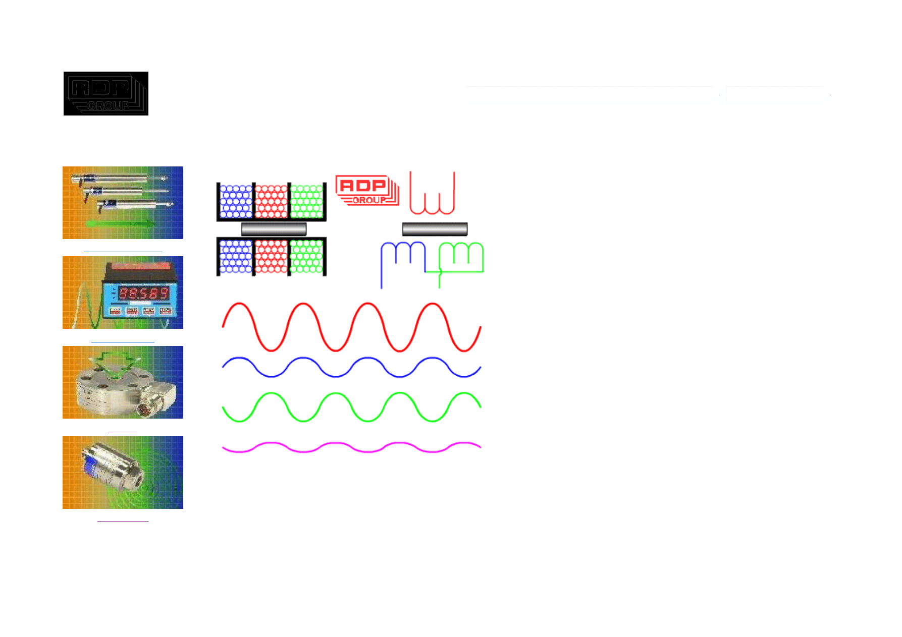
An LVDT Displacement Transducer comprises 3 coils; a
primary and two secondaries.
The transfer of current between the primary and the
secondaries of the LVDT displacement transducer is
controlled by the position of a magnetic core called an
armature.
On our position measurement LVDTs, the two
transducer secondaries are connected in opposition.
At the centre of the position measurement stroke, the
two secondary voltages of the displacement transducer
are equal but because they are connected in opposition
the resulting output from the sensor is zero.
As the LVDTs armature moves away from centre, the
result is an increase in one of the position sensor
secondaries and a decrease in the other. This results in
an output from the measurement sensor.
With LVDTs, the phase of the output (compared with
the excitation phase) enables the electronics to know
which half of the coil the armature is in.
The strength of the LVDT sensor's principle is that there
is no electrical contact across the transducer position
sensing element which for the user of the sensor means
Strona 1 z 2
How it Works - LVDT
2009-05-20
http://www.rdpe.com/ex/hiw-lvdt.htm

Technical manuals
How it Works
Contact us
Freeware
clean data, infinite resolution and a very long life.
Our range of signal conditioning electronics for LVDTs
handles all of the above so that you get an output of
voltage, current or serial data proportional to the
measurement position of the displacement transducer.
All dimensions and specifications are
nominal.
www.rdpe.com/ex/hiw-lvdt.htm
20080110
Due to our policy of on-going development, specifications may change without notice. Any modification may
affect some or all of the specifications for our equipment.
USA & Canada
RDP Electrosense
2216 Pottstown Pike
Pottstown, PA 19465
USA
Tel: 610-469-0850
Tel: 800-334-5838
Fax: 610-469-0852
Email: info@rdpe.com
Rest of the world
RDP Electronics Ltd
Grove Street, Heath Town
Wolverhampton, West Midlands, WV10 0PY
United Kingdom
Tel: +44 1902 457512
Fax: +44 1902 452000
Email: sales@rdpe.com
URL: www.rdpe.com
-
Strona 2 z 2
How it Works - LVDT
2009-05-20
http://www.rdpe.com/ex/hiw-lvdt.htm
Contents
Menu
How it Works - Strain Gauge Pressure Transducer
Displacement
Electronics
Load
Pressure
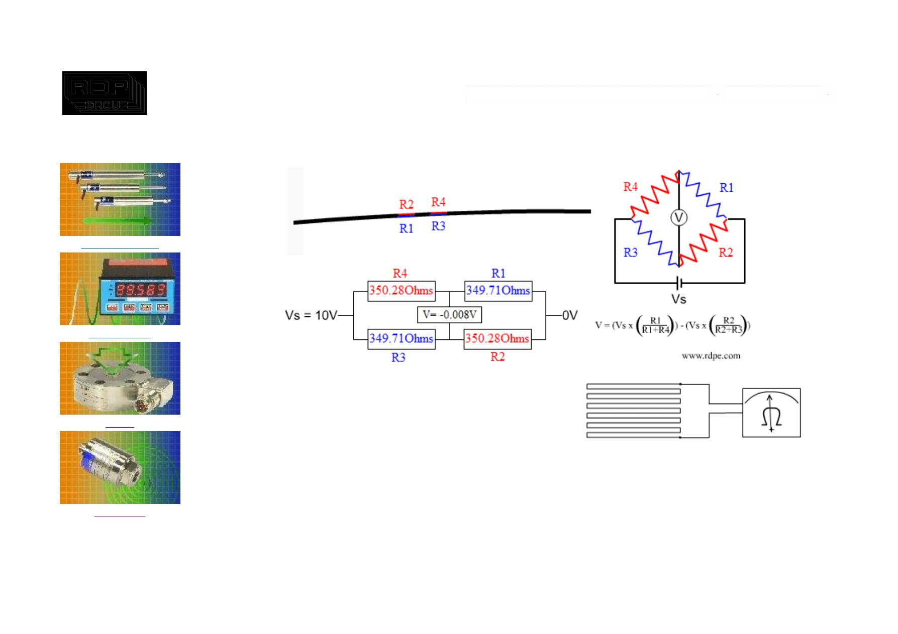
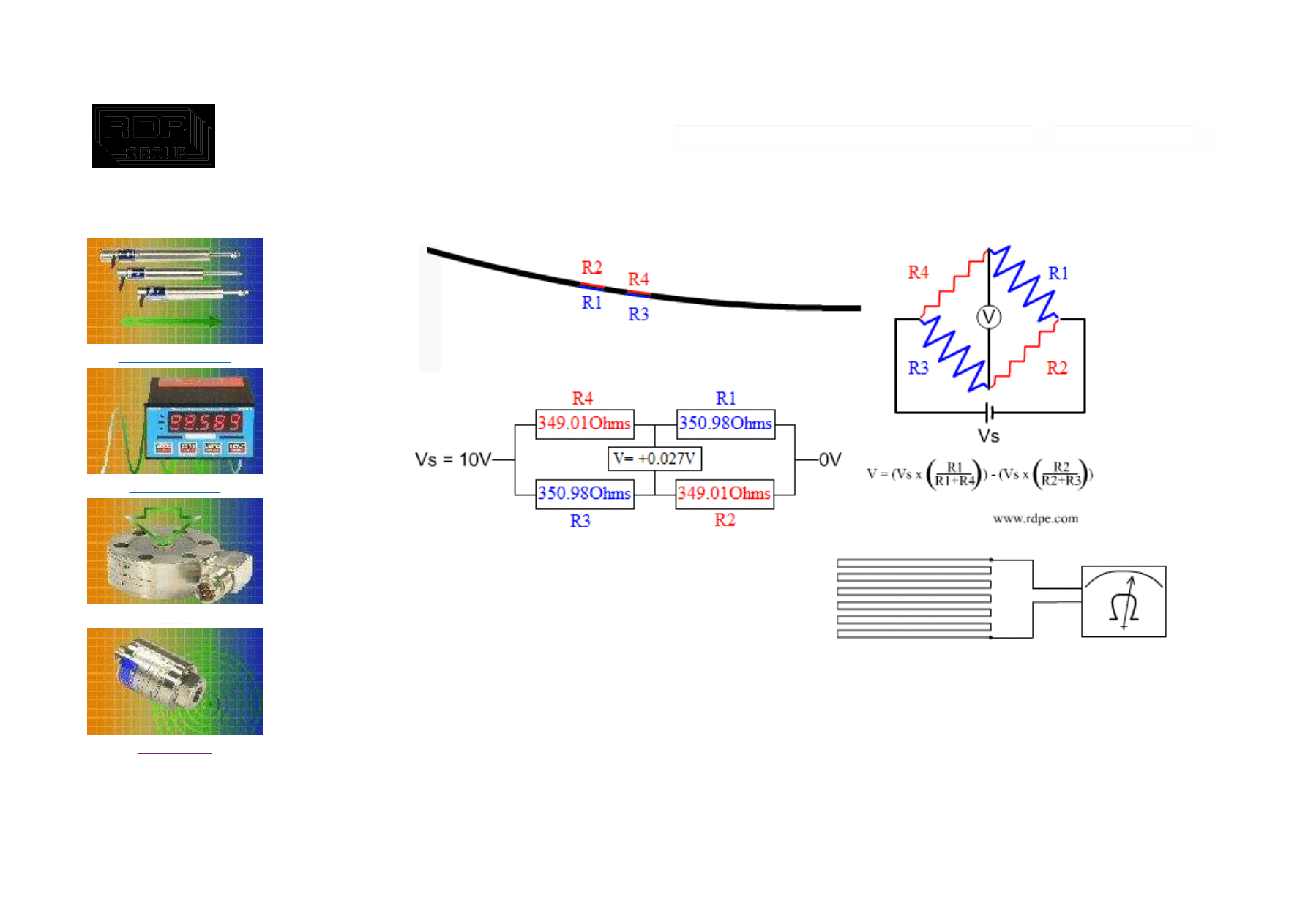
A strain gauge is a long length of conductor arranged in a zigzag
pattern on a membrane.
When it is stretched, its resistance increases.
Strain gauges are mounted in the same direction as the strain and often in fours to form a full 'Wheatstone Bridge'.
The diagram above represents what might happen if a strip of metal were fitted with four gauges.
An downward bend stretches the gauges on the top and compresses those on the bottom.
A pressure transducer contains a diaphragm which is deformed by the pressure which can be measured by a strain
gauged element.
Strona 1 z 2
How it Works - Strain Gauge Pressure Transducer
2009-05-20
http://www.rdpe.com/ex/hiw-sgpt.htm

Technical manuals
How it Works
Contact us
Freeware
All dimensions and specifications are
nominal.
www.rdpe.com/ex/hiw-sgpt.htm
20080110
Due to our policy of on-going development, specifications may change without notice. Any modification may affect
some or all of the specifications for our equipment.
USA & Canada
RDP Electrosense
2216 Pottstown Pike
Pottstown, PA 19465
USA
Tel: 610-469-0850
Tel: 800-334-5838
Fax: 610-469-0852
Email: info@rdpe.com
Rest of the world
RDP Electronics Ltd
Grove Street, Heath Town
Wolverhampton, West Midlands, WV10 0PY
United Kingdom
Tel: +44 1902 457512
Fax: +44 1902 452000
Email: sales@rdpe.com
URL: www.rdpe.com
-
Strona 2 z 2
How it Works - Strain Gauge Pressure Transducer
2009-05-20
http://www.rdpe.com/ex/hiw-sgpt.htm

Contents
Menu
How it Works - Dc LVDT
Displacement
Electronics
Load
Pressure
Primary excitation
Secondary 1
Secondary 2
Secondary 1 - Secondary 2
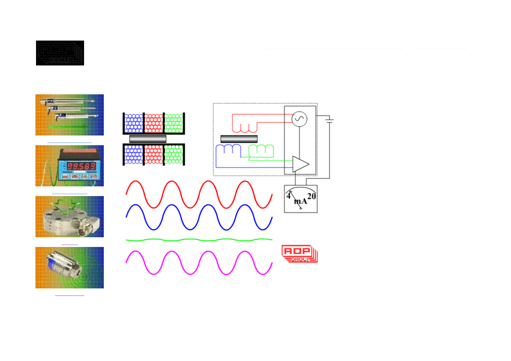
An LVDT Displacement Transducer
comprises 3 coils; a primary and two
secondaries.
The transfer of current between the
primary and the secondaries of the LVDT
displacement transducer is controlled by
the position of a magnetic core called an
armature.
On our position measurement LVDTs, the
two transducer secondaries are
connected in opposition.
At the centre of the position measurement
stroke, the two secondary voltages of the
displacement transducer are equal but
because they are connected in opposition
the resulting output from the sensor is
zero.
As the LVDTs armature moves away from
centre, the result is an increase in one of
the position sensor secondaries and a
decrease in the other. This results in an
output from the measurement sensor.
With LVDTs, the phase of the output
Strona 1 z 3
How it Works - Dc LVDT
2009-05-20
http://www.rdpe.com/ex/hiw-lvdtdc.htm

Technical manuals
How it Works
Contact us
Freeware
(compared with the excitation phase)
enables the electronics to know which
half of the coil the armature is in.
The strength of the LVDT sensor's
principle is that there is no electrical
contact across the transducer position
sensing element which for the user of the
sensor means clean data, infinite
resolution and a very long life.
An oscillator/demodulator circuit built into
the displacement transducer supplies the
excitation and converts the return signal
to a dc voltage.
As the transducer contains internal signal
conditioning electronics, there is no need
for external signal conditioning.
All dimensions and specifications are
nominal.
www.rdpe.com/ex/hiw-lvdtdc.htm
20080110
Due to our policy of on-going development, specifications may change without notice. Any modification may
affect some or all of the specifications for our equipment.
USA & Canada
RDP Electrosense
2216 Pottstown Pike
Pottstown, PA 19465
USA
Tel: 610-469-0850
Tel: 800-334-5838
Fax: 610-469-0852
Email: info@rdpe.com
Rest of the world
RDP Electronics Ltd
Grove Street, Heath Town
Wolverhampton, West Midlands, WV10 0PY
United Kingdom
Tel: +44 1902 457512
Fax: +44 1902 452000
Email: sales@rdpe.com
Strona 2 z 3
How it Works - Dc LVDT
2009-05-20
http://www.rdpe.com/ex/hiw-lvdtdc.htm

URL: www.rdpe.com
-
Strona 3 z 3
How it Works - Dc LVDT
2009-05-20
http://www.rdpe.com/ex/hiw-lvdtdc.htm
Contents
Menu
How it Works - 4 to 20mA LVDT
Displacement
Electronics
Load
Pressure
Primary excitation
Secondary 1
Secondary 2
Secondary 1 - Secondary 2
An LVDT Displacement Transducer
comprises 3 coils; a primary and two
secondaries.
The transfer of current between the
primary and the secondaries of the LVDT
displacement transducer is controlled by
the position of a magnetic core called an
armature.
On our position measurement LVDTs, the
two transducer secondaries are
connected in opposition.
At the centre of the position measurement
stroke, the two secondary voltages of the
displacement transducer are equal but
because they are connected in opposition
the resulting output from the sensor is
zero.
As the LVDTs armature moves away from
centre, the result is an increase in one of
the position sensor secondaries and a
decrease in the other. This results in an
output from the measurement sensor.
With LVDTs, the phase of the output
Strona 1 z 3
How it Works - 4 to 20mA LVDT
2009-05-20
http://www.rdpe.com/ex/hiw-lvdtma.htm

Technical manuals
How it Works
Contact us
Freeware
(compared with the excitation phase)
enables the electronics to know which
half of the coil the armature is in.
The strength of the LVDT sensor's
principle is that there is no electrical
contact across the transducer position
sensing element which for the user of the
sensor means clean data, infinite
resolution and a very long life.
An oscillator/demodulator circuit built into
the displacement transducer is powered
by and controls the 4-20mA output.
As the transducer contains internal signal
conditioning electronics, there is no need
for external signal conditioning.
All dimensions and specifications are
nominal.
www.rdpe.com/ex/hiw-lvdtma.htm
20080110
Due to our policy of on-going development, specifications may change without notice. Any modification may
affect some or all of the specifications for our equipment.
USA & Canada
RDP Electrosense
2216 Pottstown Pike
Pottstown, PA 19465
USA
Tel: 610-469-0850
Tel: 800-334-5838
Fax: 610-469-0852
Email: info@rdpe.com
Rest of the world
RDP Electronics Ltd
Grove Street, Heath Town
Wolverhampton, West Midlands, WV10 0PY
United Kingdom
Tel: +44 1902 457512
Fax: +44 1902 452000
Email: sales@rdpe.com
URL: www.rdpe.com
Strona 2 z 3
How it Works - 4 to 20mA LVDT
2009-05-20
http://www.rdpe.com/ex/hiw-lvdtma.htm

-
Strona 3 z 3
How it Works - 4 to 20mA LVDT
2009-05-20
http://www.rdpe.com/ex/hiw-lvdtma.htm
Contents
Menu
How it Works - Magnetostrictive
Displacement
Electronics
Load
Pressure
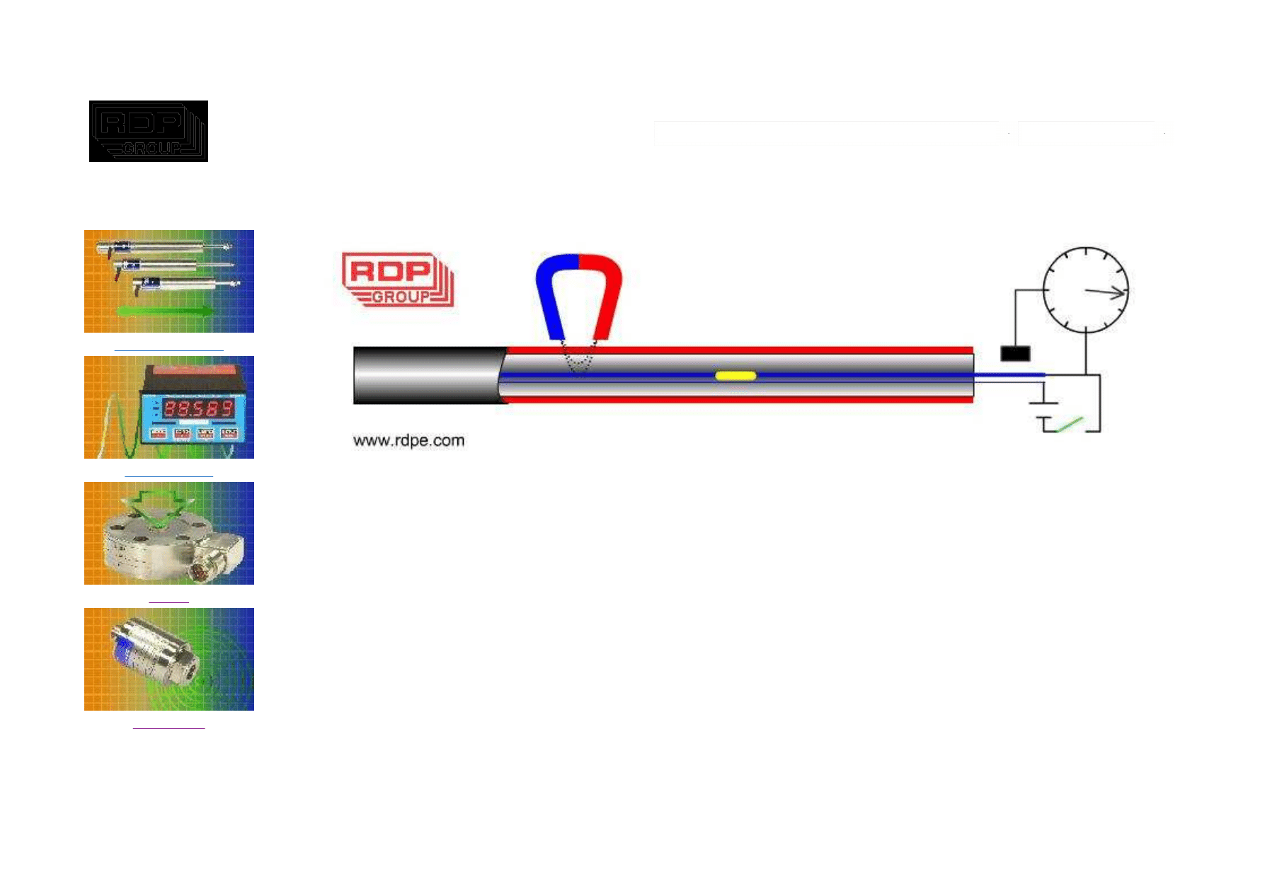
The transducer comprises a sensor element (shown in blue), a signal converter (at the right of the diagram) and a
position magnet.
The signal converter applies an electrical pulse to the sensor element and simultaneously starts a timer.
The magnetic field generated around the sensing element by the electrical pulse interacts with the field of the
position magnet and produces a mechanical pulse.
The mechanical pulse travels back down the sensing element where a sensor in the signal converter detects it and
stops the timer.
As the speed of the mechanical pulse is constant, the time taken for the pulse to reach the sensor can be used to
accurately measure the position of the magnet.
Strona 1 z 2
How it Works - Magnetostrictive
2009-05-20
http://www.rdpe.com/ex/hiw-magneto.htm

Technical manuals
How it Works
Contact us
Freeware
Typically the mechanical pulse travels at 2800m/s and the cycle process is repeated 1000 times per second.
All dimensions and specifications are
nominal.
www.rdpe.com/ex/hiw-magneto.htm
20080110
Due to our policy of on-going development, specifications may change without notice. Any modification may affect
some or all of the specifications for our equipment.
USA & Canada
RDP Electrosense
2216 Pottstown Pike
Pottstown, PA 19465
USA
Tel: 610-469-0850
Tel: 800-334-5838
Fax: 610-469-0852
Email: info@rdpe.com
Rest of the world
RDP Electronics Ltd
Grove Street, Heath Town
Wolverhampton, West Midlands, WV10 0PY
United Kingdom
Tel: +44 1902 457512
Fax: +44 1902 452000
Email: sales@rdpe.com
URL: www.rdpe.com
-
Strona 2 z 2
How it Works - Magnetostrictive
2009-05-20
http://www.rdpe.com/ex/hiw-magneto.htm
Contents
Menu
How it Works - Strain Gauge Load Cell
Displacement
Electronics
Load
Pressure
A strain gauge is a long length of conductor arranged in a zigzag
pattern on a membrane.
When it is stretched, its resistance increases.
Strain gauges are mounted in the same direction as the strain and often in fours to form a full 'Wheatstone Bridge'.
The diagram above represents what might happen if a strip of metal were fitted with four gauges.
An downward bend stretches the gauges on the top and compresses those on the bottom.
A load cell may contain several similar strain gauges elements.
Strona 1 z 2
How it Works - Strain Gauge Load Cell
2009-05-20
http://www.rdpe.com/ex/hiw-sglc.htm

Technical manuals
How it Works
Contact us
Freeware
All dimensions and specifications are
nominal.
www.rdpe.com/ex/hiw-sglc.htm
20080110
Due to our policy of on-going development, specifications may change without notice. Any modification may affect
some or all of the specifications for our equipment.
USA & Canada
RDP Electrosense
2216 Pottstown Pike
Pottstown, PA 19465
USA
Tel: 610-469-0850
Tel: 800-334-5838
Fax: 610-469-0852
Email: info@rdpe.com
Rest of the world
RDP Electronics Ltd
Grove Street, Heath Town
Wolverhampton, West Midlands, WV10 0PY
United Kingdom
Tel: +44 1902 457512
Fax: +44 1902 452000
Email: sales@rdpe.com
URL: www.rdpe.com
-
Strona 2 z 2
How it Works - Strain Gauge Load Cell
2009-05-20
http://www.rdpe.com/ex/hiw-sglc.htm

Contents
Menu
How it Works - Strain Gauge Pressure Transducer
Displacement
Electronics
Load
Pressure
A strain gauge is a long length of conductor arranged in a zigzag
pattern on a membrane.
When it is stretched, its resistance increases.
Strain gauges are mounted in the same direction as the strain and often in fours to form a full 'Wheatstone Bridge'.
The diagram above represents what might happen if a strip of metal were fitted with four gauges.
An downward bend stretches the gauges on the top and compresses those on the bottom.
A pressure transducer contains a diaphragm which is deformed by the pressure which can be measured by a strain
gauged element.
Strona 1 z 2
How it Works - Strain Gauge Pressure Transducer
2009-05-20
http://www.rdpe.com/ex/hiw-sgpt.htm

Technical manuals
How it Works
Contact us
Freeware
All dimensions and specifications are
nominal.
www.rdpe.com/ex/hiw-sgpt.htm
20080110
Due to our policy of on-going development, specifications may change without notice. Any modification may affect
some or all of the specifications for our equipment.
USA & Canada
RDP Electrosense
2216 Pottstown Pike
Pottstown, PA 19465
USA
Tel: 610-469-0850
Tel: 800-334-5838
Fax: 610-469-0852
Email: info@rdpe.com
Rest of the world
RDP Electronics Ltd
Grove Street, Heath Town
Wolverhampton, West Midlands, WV10 0PY
United Kingdom
Tel: +44 1902 457512
Fax: +44 1902 452000
Email: sales@rdpe.com
URL: www.rdpe.com
-
Strona 2 z 2
How it Works - Strain Gauge Pressure Transducer
2009-05-20
http://www.rdpe.com/ex/hiw-sgpt.htm
Wyszukiwarka
Podobne podstrony:
Ściągi, Automatyka 3, Czujniki generacyjne zasada działania czujnika polega na tym, że zmiana szerok
Czujniki pomiarowe Budowa i zasada dzialania
skaner zasada dzialania1
F 1 Zasada działania tranzystora bipolarnego
Budowa pojazdów samochodowych -Zasada działania silnika dwusuwowego semestr 1, Motoryzacja
Budowa i zasada działania układu pneumatycznego z?S oraz kryteria oceny
Zasada Dzialania PID
Budowa i zasada działania FDD
Zasada działania maszyny indukcyjnej a
22 Zasada dzialania i charakteryst (2)
Budowa i zasada działania mikroskopu optycznego metalograficznego
ZASADA DZIAŁANIA?M
Budowa i zasada działania lasera, fizyka, Referaty
ZASADA DZIAŁANIA SILNIKA DWUSUWOWEGO, MOTORYZACJA, ▼ Silniki Spalinowe ▼
Budowa i zasada działania galwanometru statycznego
Zasada działania oczyszczalni ścieków
Budowa pojazdów samochodowych zasada działania silnika czterosuwowego i?z rozrządu semestr 1 (2)
więcej podobnych podstron