
Initial Print Date: 10/07
Table of Contents
Subject
Page
Wear Safety goggles! . . . . . . . . . . . . . . . . . . . . . . . . . . . . . . . . . . . . . . . . .4
No Smoking! . . . . . . . . . . . . . . . . . . . . . . . . . . . . . . . . . . . . . . . . . . . . . . . .5
Important Service Information . . . . . . . . . . . . . . . . . . . . . . . . . . . . . . . . .6
Refrigerant Circuit . . . . . . . . . . . . . . . . . . . . . . . . . . . . . . . . . . . . . . . . . . . . . .6
Compressor Service . . . . . . . . . . . . . . . . . . . . . . . . . . . . . . . . . . . . . . . . . . . .7
Refrigerant Oil Service Procedure . . . . . . . . . . . . . . . . . . . . . . . . . . . . . . . .9
Typical Use: A/C Performance Quick Check . . . . . . . . . . . . . . . . .13
Diagnostic Equipment Temperature Probe . . . . . . . . . . . . . . . . . . . . .13
Pyrometer . . . . . . . . . . . . . . . . . . . . . . . . . . . . . . . . . . . . . . . . . . . . . . . . . .14
Recycling/Charging Equipment . . . . . . . . . . . . . . . . . . . . . . . . . . . . . . . . .14
Connecting Recycling/Charging Equipment to a Vehicle . . . . . . . . . . .15
Refrigerant Recovery Process . . . . . . . . . . . . . . . . . . . . . . . . . . . . . . . . . . .16
Recycling Process . . . . . . . . . . . . . . . . . . . . . . . . . . . . . . . . . . . . . . . . . . . . .16
Recharging Process . . . . . . . . . . . . . . . . . . . . . . . . . . . . . . . . . . . . . . . . . . .17
Refrigerant Leak Detectors . . . . . . . . . . . . . . . . . . . . . . . . . . . . . . . . . . . . .18
Sniffer Leak Detector . . . . . . . . . . . . . . . . . . . . . . . . . . . . . . . . . . . . . . . .18
Fluorescent Dye . . . . . . . . . . . . . . . . . . . . . . . . . . . . . . . . . . . . . . . . . . .18
Leak Testing the A/C System . . . . . . . . . . . . . . . . . . . . . . . . . . . . . . . . .19
Symptoms Diagnosis and Gauge Readings . . . . . . . . . . . . . . . . . . . .20
Refrigerant Pressure . . . . . . . . . . . . . . . . . . . . . . . . . . . . . . . . . . . . . . . . . . .20
A/C Performance Efficiency Test . . . . . . . . . . . . . . . . . . . . . . . . . . . . . . .21
Pre-conditions . . . . . . . . . . . . . . . . . . . . . . . . . . . . . . . . . . . . . . . . . . . . .21
A/C Efficiency Test . . . . . . . . . . . . . . . . . . . . . . . . . . . . . . . . . . . . . . . . . .22
Normal Operation Readings . . . . . . . . . . . . . . . . . . . . . . . . . . . . . . . . . . . .23
Ambient Temperature/Relative Humidity Reference Chart . . . . . . . . . .24
Outlet Temperature Initially Cold then Warm . . . . . . . . . . . . . . . . . . . . . .25
Outlet Temperature Not Cold . . . . . . . . . . . . . . . . . . . . . . . . . . . . . . . . . . .26
Air Conditioning Service and Diagnosis
Revision Date:

Subject
Page
Outlet Temperature Cool but Not Cold . . . . . . . . . . . . . . . . . . . . . . . . . . .27
Not Cold with Visible Icing Near TEV . . . . . . . . . . . . . . . . . . . . . . . . . . . .28
Not Cold with Loud Compressor Operation . . . . . . . . . . . . . . . . . . . . . . .29
Not Cold with Visible Icing Near Dryer . . . . . . . . . . . . . . . . . . . . . . . . . . .30
Not Cold with Compressor Frequent Cycling . . . . . . . . . . . . . . . . . . . . .31
Service Information . . . . . . . . . . . . . . . . . . . . . . . . . . . . . . . . . . . . . . . . . . .32
Condenser Service . . . . . . . . . . . . . . . . . . . . . . . . . . . . . . . . . . . . . . . . . .32
Evaporator Service . . . . . . . . . . . . . . . . . . . . . . . . . . . . . . . . . . . . . . . . . .32
Expansion Valve Service . . . . . . . . . . . . . . . . . . . . . . . . . . . . . . . . . . . . .33
Compressor Service . . . . . . . . . . . . . . . . . . . . . . . . . . . . . . . . . . . . . . . .34
Compressor Running-in Procedure . . . . . . . . . . . . . . . . . . . . . . . .35

3
Air Conditioning Service and Diagnosis
Air Conditioning Service and Diagnosis
Model: All
Production: All
After completion of this module you will be able to:
• Understand the precautions that need to be observed when working
on a climate control system.
• Identify the tools and equipment necessary to work on BMW Climate
Control Systems.
• Describe the different service procedures necessary to service a
BMW Climate Control System.
• Identify some of the most common A/C system scenarios.

4
Air Conditioning Service and Diagnosis
Product Properties
Although R134a is non-toxic, non-flammable and not explosive with air in any mix ratio at
normal temperatures, various safety measures must still be observed. The filled refriger-
ant circuit is pressurized. The refrigerant must be extracted when performing repairs on
the air conditioning system. As a gas, R134a is colorless, odorless and heavier than air.
The various refrigerants that are used in vehicle air conditioning systems belong to the
substance class of the new generation of refrigerants based on chlorine-free, partly fluo-
rinated hydrocarbons (H-FCs, R134a).
With regard to their physical properties, these are refrigerants that condense under pres-
sure. They are subject to the pressure vessel ordinance and must be filled only in
approved and correspondingly identified pressurized gas containers. Specific require-
ments that must be adhered to apply to their safe and correct use.
Handling Refrigerant
After opening refrigerant containers, the content can escape in liquid or vapor form.
The higher the pressure in the container the more intense the reaction. The pressure
level depends on two conditions:
• What type of refrigerant is in the container? The lower the boiling point, the higher
the pressure.
• How high is the temperature? The higher the temperature, the higher the pressures.
Wear Safety goggles!
Wear safety goggles. They prevent refrigerant from
entering the eyes and possibly causing serious
damage due to its freezing effect.
Wear protective gloves, do not allow liquid refriger-
ant to make contact with the skin!
Refrigerants effectively dissolve greases and oils.
They therefore remove the protective oily layer
when they come in contact with the skin. Skin
without the protective oily layer is sensitive to low
temperatures and susceptible to illness causing
germs.
When it evaporates, the refrigerant absorbs heat from the environment even if this is
human skin. Very low temperatures can be reached, resulting in local frostbite (boiling
point of R12 = -30°C, R134a -26.5°C).
Safety Requirements

5
Air Conditioning Service and Diagnosis
Do not inhale refrigerant vapors in higher concentrations! Leaking refrigerant vapors
mix with the ambient air and displace the oxygen necessary for breathing. The worksta-
tions must be well ventilated if refrigerant escapes in higher concentrations.
Immediately
seek medical assistance if problems occur after inhaling refrigerant vapors! Rooms
must be sufficiently ventilated or switch on extractor system if available.
No Smoking!
Refrigerants can break down in the heat from cigarettes. The resulting substances are
toxic and must not be inhaled. Avoid welding and soldering on filled air conditioning sys-
tems! Before welding and soldering on air conditioning systems, the refrigerant must be
extracted and residue removed by blowing out the system with nitrogen.
The decomposition products produced when the refrigerant is subject to the effects of
heat are not only toxic but are also very corrosive, affecting pipes and system compo-
nents. The corrosive substances are essentially hydrogen chloride and hydrogen fluoride.
The presence of these decomposition products is associated with a pungent odor. Under
no circumstances must these substances be inhaled as they can damage the respiratory
tract, the lungs and other organs.
First Aid!
1. In the event of contact with the eyes, flush out with plenty of flowing water and seek
medical assistance.
2. In the event of contact with the skin, immediately remove soaked clothing and flush
skin with plenty of water.
3. If refrigerant vapors in high concentrations are inhaled make sure the person affected
is immediately brought out into the fresh air. Seek medical assistance. Provide oxygen
if breathing difficulties occur. If the person affected suffers breathing difficulty or is no
longer breathing, tilt back the head and perform CPR.
Handling PAG Oil
• Do not store in the vicinity of flames, heat or oxides
• Avoid contact with the eyes
• Do not inhale (vapors)
• Avoid prolonged or repeated skin contact
First Aid Measures:
• After inhalation: Take the person into the fresh air and seek medical assistance.
• After skin contact: Wash thoroughly with soap and water.
• After eye contact: Flush thoroughly with water.
• After swallowing: Seek medical assistance. Do not induce vomiting.

6
Air Conditioning Service and Diagnosis
• Store all spare parts in a dry place and keep locked.
• When installing parts, only remove the plugs just before installation. This require-
ment applies particularly to the dryer. A dryer that is not sealed can absorb moisture,
rendering it unusable. Immediately close off open pipes with plugs when performing
repairs on the refrigerant circuit.
• Keep empty refrigerant bottles closed.
• Acquire refrigerant only through BMW Parts Service or specialized trade.
• Do not perform repairs in the open under moist weather conditions.
• Replace the dryer following intervention (repair) in the refrigerant circuit if it was left
open for longer than 24 hours or there was a leak in the air conditioning system.
• Do not use refrigerant oil from open containers.
• Moisture in the refrigerant circuit not only diminishes the cooling capacity but also
oxidation can cause soiling of the air conditioning system, resulting in expensive
repairs and down-time.
• Evacuate the refrigerant circuit before placing it into operation. Additional drying can
be achieved by interrupting the evacuation process and flushing with refrigerant or
blowing through with nitrogen (if available) prior to initial operation. This procedure
can increase the cooling capacity again if it was diminished as the result of moisture.
• In warranty cases, plugs must be fitted on the old parts in order to be able to deter-
mine the cause of the damage.
Refrigerant Circuit
The following points must be observed when working on the refrigerant circuit:
• Extract all the refrigerant before opening the refrigerant circuit.
• After extracting the refrigerant, measure and replace the quantity of oil also extracted.
• Replenish the prescribed quantity of oil (specified in TIS) when replacing compo-
nents.
• First evacuate the system for at least 30 minutes before refilling the circuit with
refrigerant.
• Always replace the liquid reservoir (dryer) if there is a leak in the system or it was
opened for longer than 24 hours during repair.
• Always replace the seals of the connections that were opened and wet with oil prior
to assembly.
Important Service Information

7
Air Conditioning Service and Diagnosis
Compressor Service
• When troubleshooting a noisy compressor complaint, make sure the noise is present
only when the clutch is engaged.
• If it is present when the clutch is not engaged, remove the compressor drive belt
and check again.
• If the noise continues, it is not related to the compressor.
• If removing the drive belt reduces or eliminates the noise, check the torque of the
compressor and bracket mounting bolts.
• Check the belt tension and condition, and tensioner pullies which can produce
rattling noises that would sound like a defective compressor.
• A loose/slipping belt can cause noise.
• A belt that is too tight can damage the clutch bearings.
• If the compressor is noisy with the compressor clutch engaged, make sure the
system is charged with the correct amount of refrigerant.
• An over-charged system can cause compressor noise.
• If the A/C system is overcharged with refrigerant, the liquid entering the compressor
can damage it.
• When troubleshooting a noisy compressor complaint, recover the refrigerant and
recharge the system with the correct amount.
• A failed compressor must be returned with the inlet and outlet ports sealed using
the plastic caps from the replacement compressor. Otherwise the “failed” compres-
sor will be damaged by moisture, and it will be impossible for Warranty to analyze it.
8
Air Conditioning Service and Diagnosis
Compressors with plastic pulley:
• Avoid impact on the plastic pulley (through tools, contact with base).
• Send back damaged compressors only in original packaging.
Note: After replacing compressor It is important to perform the following run-
ning-in procedure when operating a new compressor for the first time.
• Switch off air conditioning system.
• Set all air outlet nozzles on the instrument panel to "OFF".
• Start engine and allow idle speed to stabilize.
• Set blower capacity to min. 75% of the maximum blower capacity.
• Switch on air conditioning and allow to run for at least 2 minutes at idle speed.
Risk of damage at higher speed! (Refer to DIS Service Functions for more
detailed instructions)
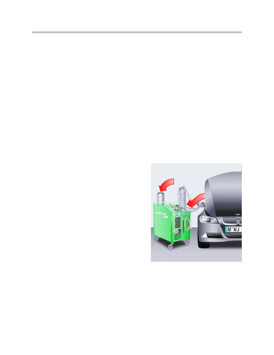
When extracting the refrigerant from the air conditioning system, the refrigerator
oil is also removed and collected in the oil separator of the service station.
Following extraction, the refrigerant in the ser-
vice station must be cleaned as there still may
be a liquid refrigerant-oil mixture in the oil sepa-
rator. The cleaning procedure fully evaporates
the refrigerant leaving only the refrigerant oil
previously collected in the oil separator.
Measure and note down this quantity of refrig-
erator oil.
Note: For details on compressor replacement, see the TIS, Group 64
9
Air Conditioning Service and Diagnosis
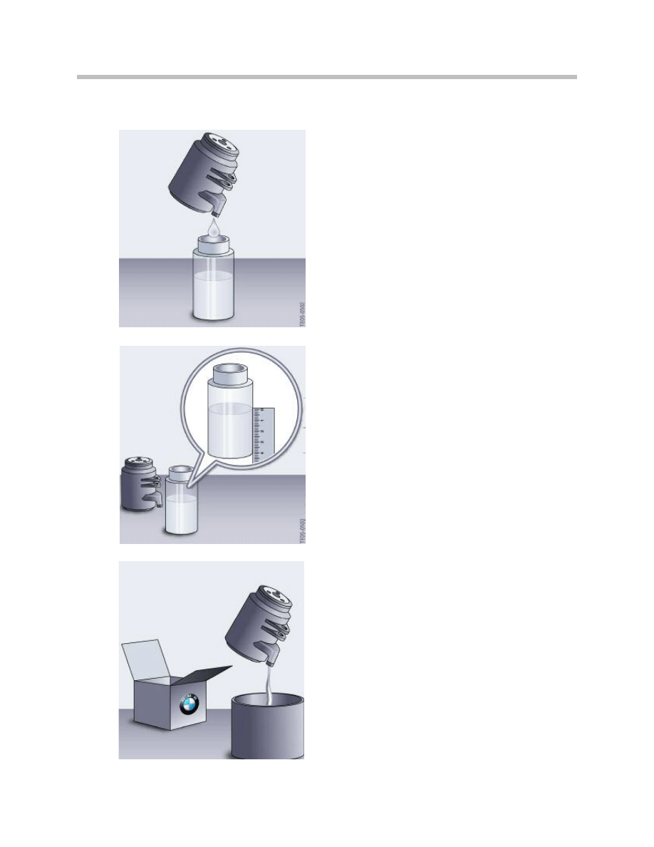
Empty the refrigerant oil remaining in the old com-
pressor via the filler plug into a measuring beaker.
Measure the collected quantity of refrigerant oil from
the old compressor.
Depending on the version, the new compressor is
filled with 120 to 200g of refrigerant oil at the factory.
Open the filler plug and fill the entire content of the
(new) compressor into a clean container.
Replace seal if necessary.
Refrigerant Oil Service Procedure
10
Air Conditioning Service and Diagnosis
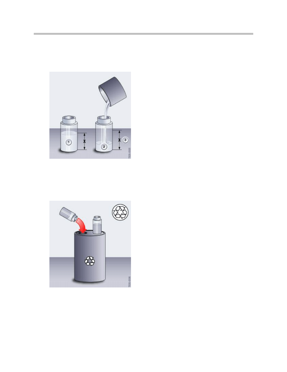
Using only new refrigerant oil, fill the same
quantity as extracted from the old compressor
+ 10g safety amount into a clean measuring
beaker and refill the new compressor.
The remainder of the new refrigerant oil can
be filled into the reservoir of the service sta-
tion. Otherwise, the surplus refrigerant oil
must be disposed of correctly.
1 = Old
2 = New
3 = Old + 10 g
The refrigerant oil extracted from the oil separator
of the service station and from the old compressor
must not be reused and must be disposed of cor-
rectly.
Note: For refrigerant oil capacities refer to TIS Operating Fluids
Section under group 64 for Air Conditioning and Heating.

11
Air Conditioning Service and Diagnosis
NOTES
PAGE
12
Air Conditioning Service and Diagnosis
There are a variety of tools and equipment used for the correct handling,
service and diagnosis of the AC system:
• Temperature Sensing Tools
• Recycling/Charging Equipment
• Refrigerant Leak Detectors
Temperature Sensing Tools
The correct way to service and diagnose a climate control system relies heavily on the
ability to accurately measuring the systems temperature output. To know the ambient
temperature and humidity is as important as the output temperature of the system,
because these are linked together as showed in the chart on the previous page.
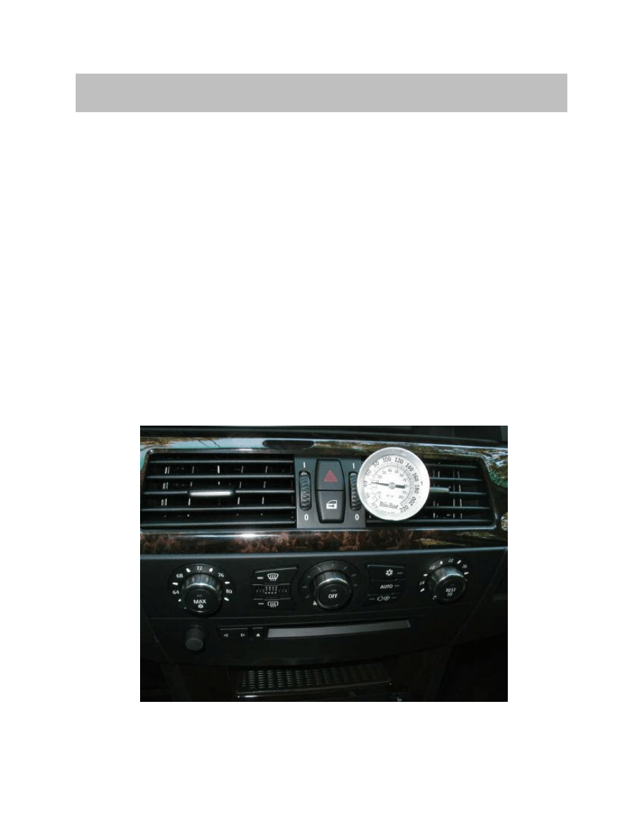
Thermometers
The most inexpensive and popular among technicians is the typical pocket thermometer.
Similar to a meat thermometer it has a flat gauge (mechanical and digital) with a long
sensing stem on the other end. Because of its design it is convenient to introduce it into
outlet vents on the vehicle.
Tools and Equipment
13
Air Conditioning Service and Diagnosis
Typical Use: A/C Performance Quick Check
Test conditions = 90°F & 50% Humidity
• Note ambient temperature
• Close all windows and doors
• Engine Speed = 1500-2000 RPM
• Blower Volume = Medium Speed
• Temperature Wheel = “Max Cold”
• “Snowflake” Button = A/C On
• Test conditions > 3 minutes
• Center vent discharge = 20°F less than the ambient temperature.
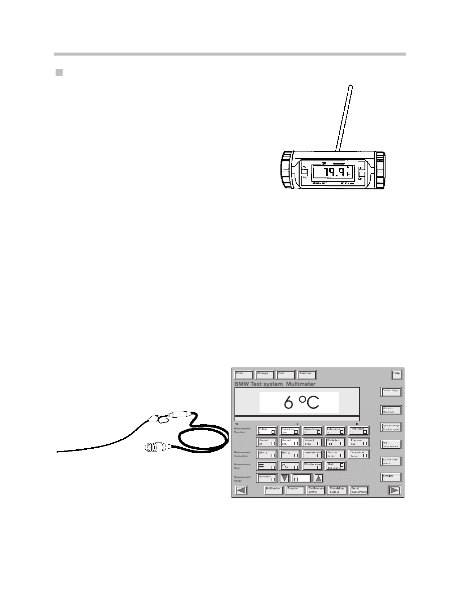
Diagnostic Equipment Temperature Probe
The Diagnosis and Information System (DIS) and GT1w/MIB (Measurement Interface
Bos) testers are equipped with a temperature sensor cable, stored in the compartment at
the rear of the tester. It can be used to measure the temperatures of liquids and gasses
from -20° to 200°C.
To use the DIS/ GT1 as a thermometer:
• Select “Measurement System” button on the DIS start screen.
• Select “Temperature C” button on the “Measuring System Multimeter” screen.
Diagnostic and Information System DIS Shown
14
Air Conditioning Service and Diagnosis
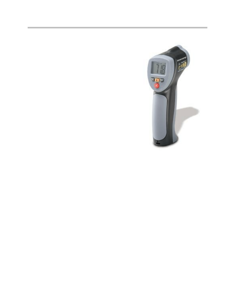
Pyrometer
A pyrometer is a non contact, point and shoot
measuring tool.
The typical design uses a laser aimed device that
consists of a lens to focus the infrared (IR) energy
on to a detector, which converts the energy to an
electrical signal that can be displayed in units of
temperature after being compensated for ambient
temperature variation.
Pyrometers are especially useful where other mea-
suring tools have limitations, like testing ther-
mostats, temperature sensors, radiator/ heater core
flow, condenser efficiency, and hard to reach ther-
mostatic expansion valves, evaporators.
Recycling/Charging Equipment
A proper system charging station includes
the following components:
• A manifold gauge set.
• A charging cylinder.
• A bulk refrigerant supply tank.
• A vacuum pump.
• Hoses for connection to the automotive A/C system.
• An electronic leak detector.
• A thermometer.
This setup will allow you to evacuate and charge an A/C system. These units filter and
remove moisture the refrigerant, before discharging it into a recovery tank.
Note: Refer to the operating instructions of the AC equipment you are working
with for specific operating instructions.
Note: The refrigerant type must be identified prior to attempting any service
on the vehicle, generally the refrigerant used is evident by the connec-
tions and by reading the label under the hood, but when in doubt a refrig-
erant identifier may be used.
15
Air Conditioning Service and Diagnosis
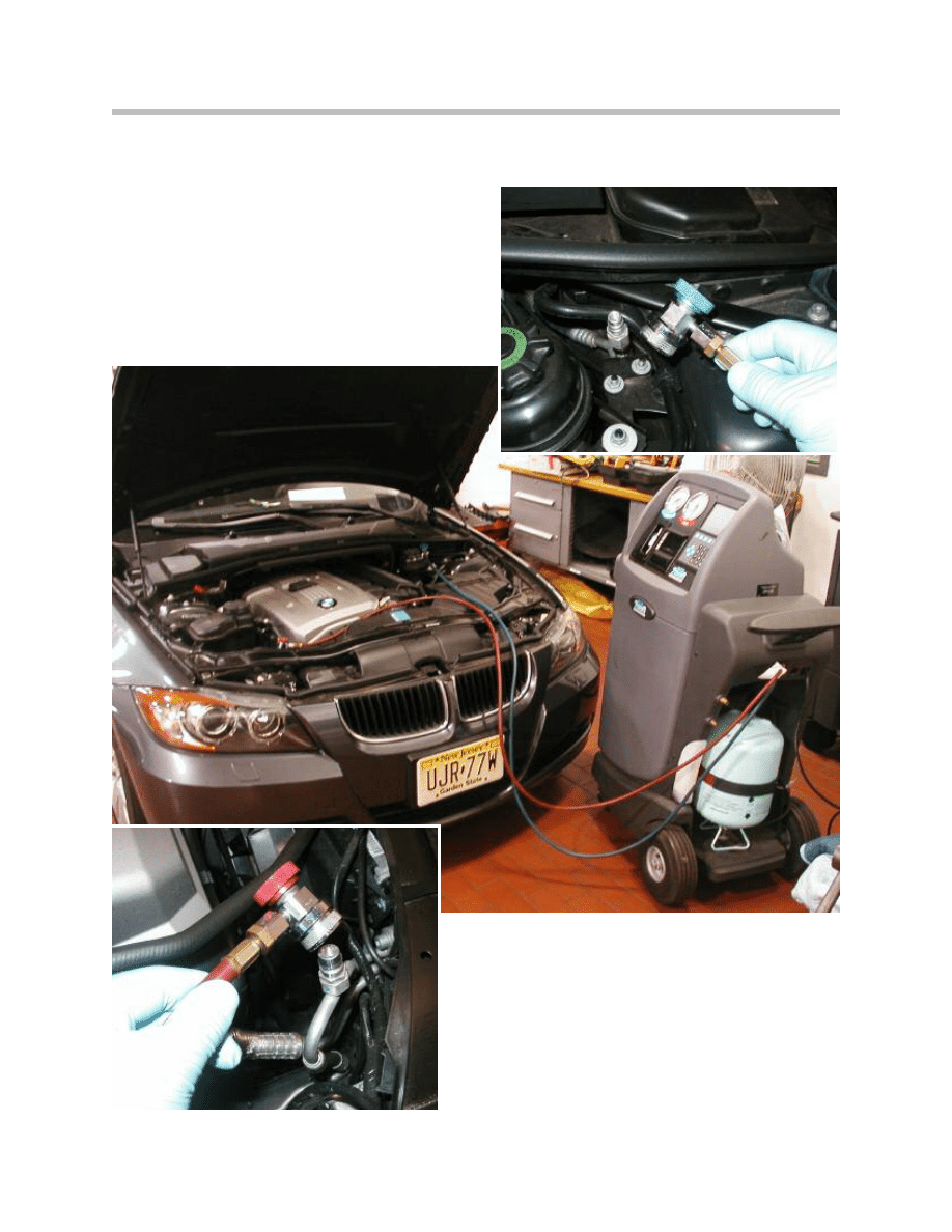
Connecting Recycling/Charging Equipment to a Vehicle
The LOW side hose is BLUE in color and incorporates
a quick disconnect type fitting (similar to an air line)
along with a shut off valve so as to minimize refrigerant
leakage.
The High side hose is RED in color and also incorpo-
rates a quick disconnect type fitting along with a shut
off valve so as to minimize refrigerant leakage.

16
Air Conditioning Service and Diagnosis
Refrigerant Recovery Process
Once the type of refrigerant has been identified, the recovery machine is plugged into a
110 ac volt power supply and connected to the vehicle. First, connect the hoses to the
service fittings on the vehicle, then open the shut off valves. The gauges will show the
system pressure on both the low and high sides. These pressures will vary depending on
the type of vehicle you are working on and how much refrigerant remains in the system.
Now, power on the recovery/recycle machine and activate the recovery process. It is
important to follow the operating instructions for the recovery equipment you are using
since every machine is slightly different.
Once recovery begins, pressures will decrease as the refrigerant is removed from the sys-
tem. The machine will empty the system and then pull it down to a vacuum state until all
of the refrigerant has been recovered. When all the refrigerant has been recovered, the
machine will automatically shut off. The shut off point is based off of vacuum pressure
and is different depending on the equipment manufacturer.
If the system holds a vacuum for at least two minutes and never shows a positive pres-
sure when the process has completed, then the refrigerant has been completely removed
from the system. However, if pressures begin to creep up after the machine has stopped,
and then there is still refrigerant trapped in the system. The recovery process has to be
repeated to remove the remaining refrigerant. Once the refrigerant has been successfully
recovered, close the shutoff valves and disconnect the recovery machine from the sys-
tem.
Check the oil collection bottle and record the amount of oil that was removed during
recovery, this amount you will add when recharging the system. The recovery stage is
complete. The technician can now open the system and make any needed repairs.
When all repairs are complete, the system can be recharged. You will learn about
recharging the system later in this lesson.
Recycling Process
As refrigerant is removed from the air conditioning system during the recovery stage, it is
drawn through a filter to remove dirt, oil, air and water. This allows for reuse of the refrig-
erant upon completion of the repair. The filter used for recycling the refrigerant needs to
replace at a recommended service interval specified by the equipment manufacturer.
There is an oil separator on the recovery machine that removes oil from the refrigerant
and stores it in a oil storage container. Record the amount of oil recovered to determine
how much oil should be used for recharging. When recharging, the amount of oil is very
important for proper operation of the system. Always check the manufacturer’s recom-
mendations before adding any oil to the vehicle. This is especially true if the system has
been opened or damaged prior to service.
17
Air Conditioning Service and Diagnosis
Recharging Process
Before the A/C system can be recharged, the air, moisture and any contaminant's that
may have entered the system during the repair must be removed. This is accomplished
by pumping the system down to a vacuum, removing the air and debris from the system.
To evacuate a system, regardless of the equipment being used, follow these guidelines:
• Connect the hoses of the recovery/recycling machine to the vehicle service fittings.
• Open both valves on the connectors.
• Now, activate the vacuum pump and run for a
minimum of 30 minutes.
• Close both valves on the connectors and turn off the vacuum pump.
• Now, write down the gauge readings and let the vehicle sit for five minutes.
• Recheck the gauge readings and note the difference.
- If the gauge readings differ more then 2” of vacuum in 5 minutes, then there
is a leak in the system.
- If the gauge readings change very little, then the system is ready to be
recharged.
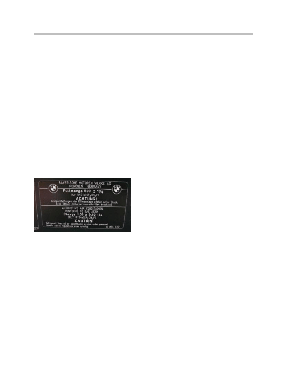
To determine the exact amount of refrigerant
needed for the vehicle’s air conditioning system,
locate the label under the hood. The label speci-
fies the type and quantity of refrigerant the sys-
tem requires. This vehicle label calls for
1.30 +/- 0.02 lbs of R134a.
Along with the refrigerant, oil has to be added back in the system. The machine collects
the oil during the recovery process. Measure the oil you recovered, then add the amount
of oil that normally collects in the components you replaced (if any). The resulting
amount of oil is to be put back into the system.
• If you have replaced the condenser or evaporator, 2 additional ounces of additional
oil must be added.
• If you have replaced the receiver dryer on a vehicle that uses the stand-alone type
receiver dryer, you would add 1 additional ounce of oil.
• Hoses do not collect much oil so if just a hose was replaced, only the oil measured
in the cup during recovery will be needed.
Follow the operating manual for the recharging equipment you are using to calibrate the
correct amount of refrigerant in the machine. Then, following the operating manual, add
the refrigerant to the A/C system.
18
Air Conditioning Service and Diagnosis
Refrigerant Leak Detectors
The two approved methods for leak testing an A/C system are a leak detector (sniffer)
and by installing fluorescent dye into the system.
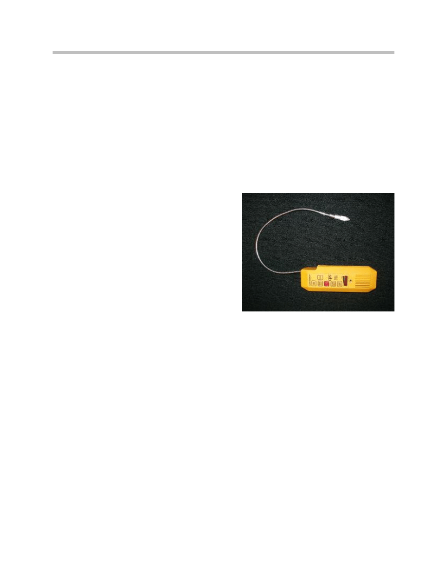
Sniffer Leak Detector
The sniffer leak detector is a device that has circuitry capable of detecting refrigerant
leaks as small as 0.40 oz per year. A small internal motor draws in air through the tip of
the probe and when refrigerant is detected, a lamp illuminates or a buzzer or audible
beeper sounds depending on the type you are using. Leak detectors calibrated for
R-134a will detect R-12, but leak detectors calibrated for R-12 will not detect R-134a.
Using a leak detector like this takes experience
and practice. Many times an oily black dust
collects on or around leaking component. This
evidence of escaping oil and refrigerant and is
a very good place to start.
A low-pressure side leak may only occur when
the system is turned off because pressures are
higher with the system off. The high-pressure
side might leak when the system is ON for
pressures are higher when the system is ON.
It is always better, if you can, to check the sys-
tem for leaks with it OFF. The cooling fan circu-
lates the air in the engine compartment and
makes it difficult to identify the leak.
The tip of the detector can be inserted in and around the suspected refrigerant leaks like
between condenser fins or the outlet vents on the dash or in the water drain hose of the
evaporator box to check for a leaking evaporator. A downside to using this method would
be that in some shops the service area may be contaminated with different gasses that
make the tool a somewhat difficult to operate.
Fluorescent Dye
To check for a leak with dye, the dye has to be added to the system and then monitored
using an ultraviolet lamp and special safety glasses. When the ultraviolet beam of light
shines on the suspected fluid, it illuminates with a yellow glow as evidence of the refriger-
ant leak. Caution must be observed when using the dye because it tends to stain every-
thing it touches, so a special cleaning solution is supplied with the kit.
Note: Refer to SIB 04 14 04 “A/C Leak detection Kit” R-134a A/C dye leak
tester has been approved for use on BMW Group vehicles.
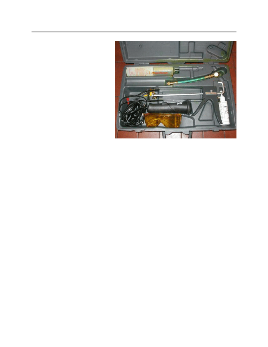
The typical dye kit includes:
• UV protecting safety glasses
• 12 volt UV/blue 100W lamp
• A container of fluorescent dye
• Dye injector device
• Hose adapters
• Dye cleaner/remover
• Instructions
Leak Testing the A/C System
Always be aware of the safety measures associated with handling refrigerant as far as
wearing eye protection, gloves and respiratory equipment. (Refer to Safety Section)
If the refrigerant leak was not identified during the evacuation, the system must be filled
before it can be tested for leaks with either dye or the electronic leak detection device.
Some helpful hints to remember when using a Dye Leak Detector:
• It is better to check the Low Side for leaks with the A/C system off.
• The high Side is best checked for leaks with the A/C system on.
• Refrigerant is heavier than air. Therefore you must always test below the
suspected lines, connections and components.
• Commonly used shop solvent fumes, wind and cooling fans may throw off
your diagnosis.
• When using the dye method, keep in mind that dye stains and a leak inside
the vehicle like an evaporator can damage the interior.
• Evaporator leaks are best diagnosed with an electronic leak detector in the
vent outlets or pressure tested with Nitrogen.
19
Air Conditioning Service and Diagnosis

20
Air Conditioning Service and Diagnosis
Refrigerant Pressure
Refrigerant pressure is directly proportional to its temperature so as the temperature
goes up so does the pressure and vice versa.
Refrigerant in the A/C system is provoked to change state from a liquid to a gas and back
again. During every change of state heat is either absorbed or given away in the
process. This thermodynamic property is put to use in the expansion valve to evaporator
section (Low Side) and in the compressor to condenser section (High Side) of all A/C
systems.
In the High side, dry, pressurized liquid refrigerant exits the receiver dryer and is made to
pass through a metered orifice in the expansion valve on its way to the evaporator. It is
here entering the Low side, that it quickly decompresses, expands and absorbs heat and
humidity from the passenger compartment as it changes state (evaporating) from liquid
to a gas. The low side pressure is directly proportional to the evaporator temperature
(see temp/pressure chart for R-134a) and dictates its heat exchanging capabilities. Low
side pressures should average 28 to 32 psi, that means that the actual pressure of a vari-
able piston displacement compressor/TEV system can be between 15 and 45 psi at any
given time.
Heat and humidity are carried away by the refrigerant gas which is then suctioned into
the compressor where it is compressed, heated and pumped through the A/C system
via the condenser. A flow of ambient air cools the condenser and the compressed, hot
refrigerant gas changes state to a liquid once again, as it flows further along the con-
denser. Here the hot gas condenses into a “warm” liquid as It gives away its heat.
The high side pressure reading directly indicates the condenser cooling efficiency.
Although High side pressures may vary between 150 to 300 lb. normally they should be
about 2 to 2.5 times the ambient temperature. Depending on humidity, an outside tem-
perature of 80°F should produce a pressure of 160 to 200 psi on the High side
(see temperature/pressure chart for R-134a). When the High side pressure is way above
the normal it may indicate that the condenser auxiliary cooling fan is not cooling the
refrigerant sufficiently. Proper air flow across the condenser insures the efficiency of the
entire system. The cooler the refrigerant is leaving the condenser the lower its pressure;
consequently the lower the pressure of the refrigerant entering the evaporator the more
heat can be absorbed from the passenger compartment.
Note: Pressure gauges are indispensible when diagnosing A/C system BUT
they are incapable of measuring the quantity or for that matter the type
of refrigerant in the system.
Symptoms Diagnosis and Gauge Readings

21
Air Conditioning Service and Diagnosis
A/C Performance Efficiency Test
Before an A/C efficiency test, satisfy the following conditions:
• Connect the diagnostic equipment and check for faults (no faults in the fault memory).
• Use a thermometer with separate gauge.
• Perform the test in a suitable work bay with an ambient temperature between
20°C and 30°C (68°F and 86°F).
Pre-conditions
1. Connect BMW diagnostic equipment to the vehicle and display evaporator
temperature.
2. Position a (pocket) thermometer with a separate gauge about 5 cm(2 in.) below the
roof liner at the height of the B-pillar. Lay the gauge facing outside of vehicle interior.
3. Heating up the vehicle interior:
• A/C button is not activated during heating up.
• Close all windows and doors.
• Set recirculated air mode.
• Select air distribution mode for footwell and defrosting.
• Maximum temperature setting.
• Maximum fan stage.
• Run engine at approx. 2000 rpm until operating temperature is reached,
then idle speed.

22
Air Conditioning Service and Diagnosis
A/C Efficiency Test
• Turn on A/C compressor at a vehicle interior temperature of 50°C.
• After 3-4 minutes, the evaporator sensor temperature must be 15°C (59°F)
or below.
If this temperature is not reached:
• Measure the amount of refrigerant collected.
• Recycle the refrigerant in the A/C system.
If the recovered refrigerant quantity does not correspond to the specified fill quantity:
• Recharge with the specified amount of refrigerant and repeat test. If fill quantity
is correct, continue troubleshooting by pressure measurement.
If fill quantity is correct:
• Continue troubleshooting by refrigerant pressure readings.
Note: For A/C systems with uncontrolled compressors only; if necessary,
then continue troubleshooting by pressure measurement.
23
Air Conditioning Service and Diagnosis
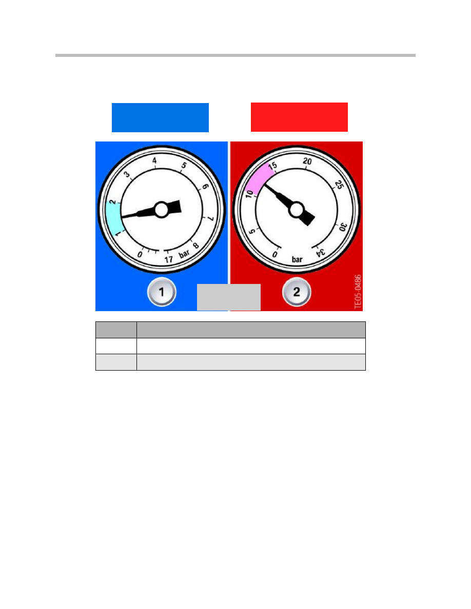
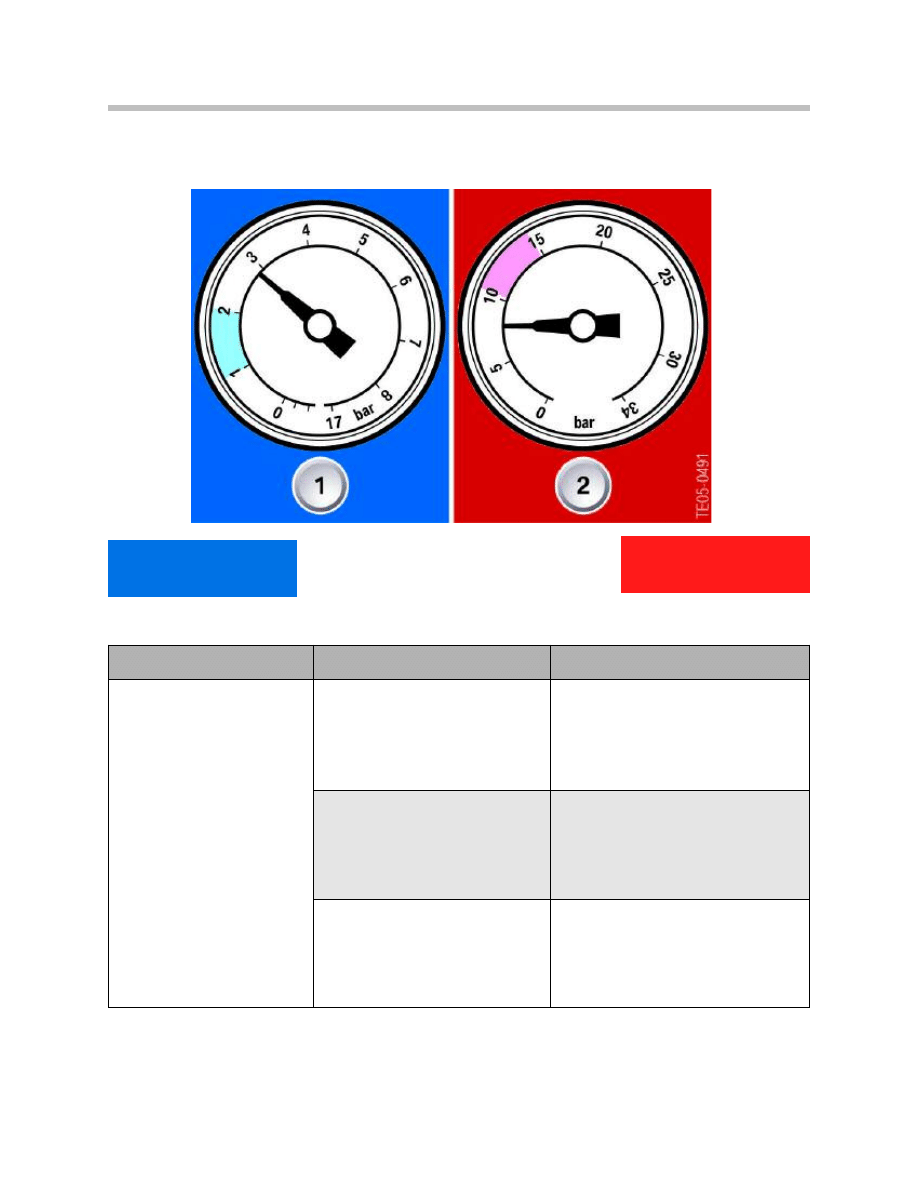
Normal Operation Readings
Outlet temperatures may vary from 40 to 68°F at any given time depending on ambient
temperature and humidity. Readings of about 20° less than ambient temperatures are
considered acceptable. Several fault symptoms involving high pressure and low pressure
are described in the following examples, together with possible corrective measures.
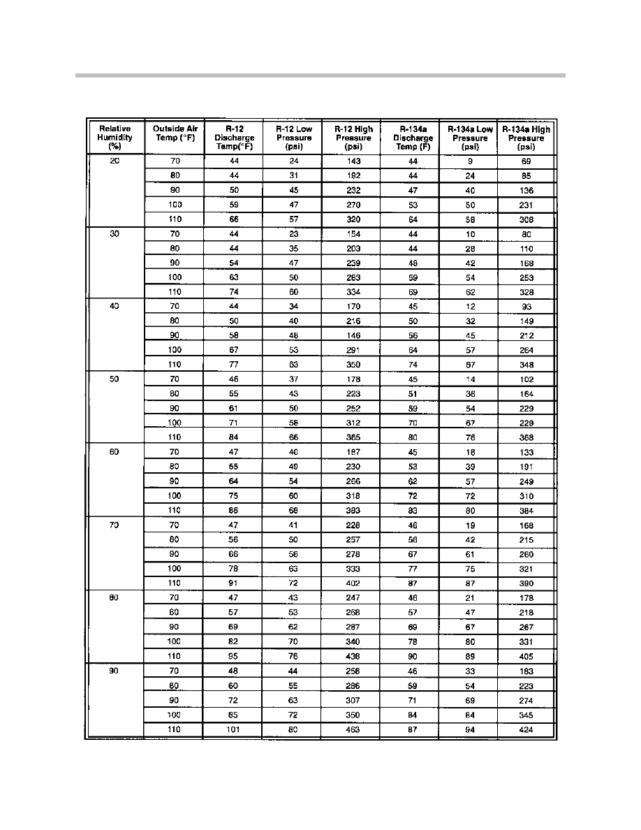
Note: Refer to S.I.B. # 641392 (3646) or the chart on the following page for
nominal air conditioning system pressures and temperatures for
R12/R134a and the effects of ambient temperature and humidity on
AC system performance.
40 to 68°F
Outlet Temp.
15 to 30 psi
150 to 225 psi
Index
Explanation
1
Low pressure - normal 1 to 2 bar (15 to 30 psi)
2
High pressure - normal 10 to15 bar (150 to 225 psi)
24
Air Conditioning Service and Diagnosis
Ambient Temperature/Relative Humidity Reference Chart
25
Air Conditioning Service and Diagnosis
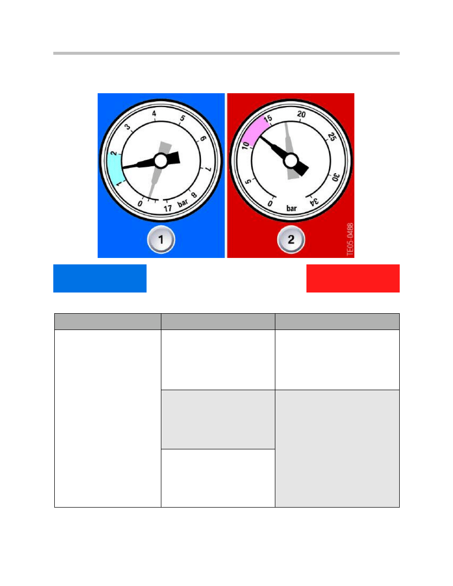
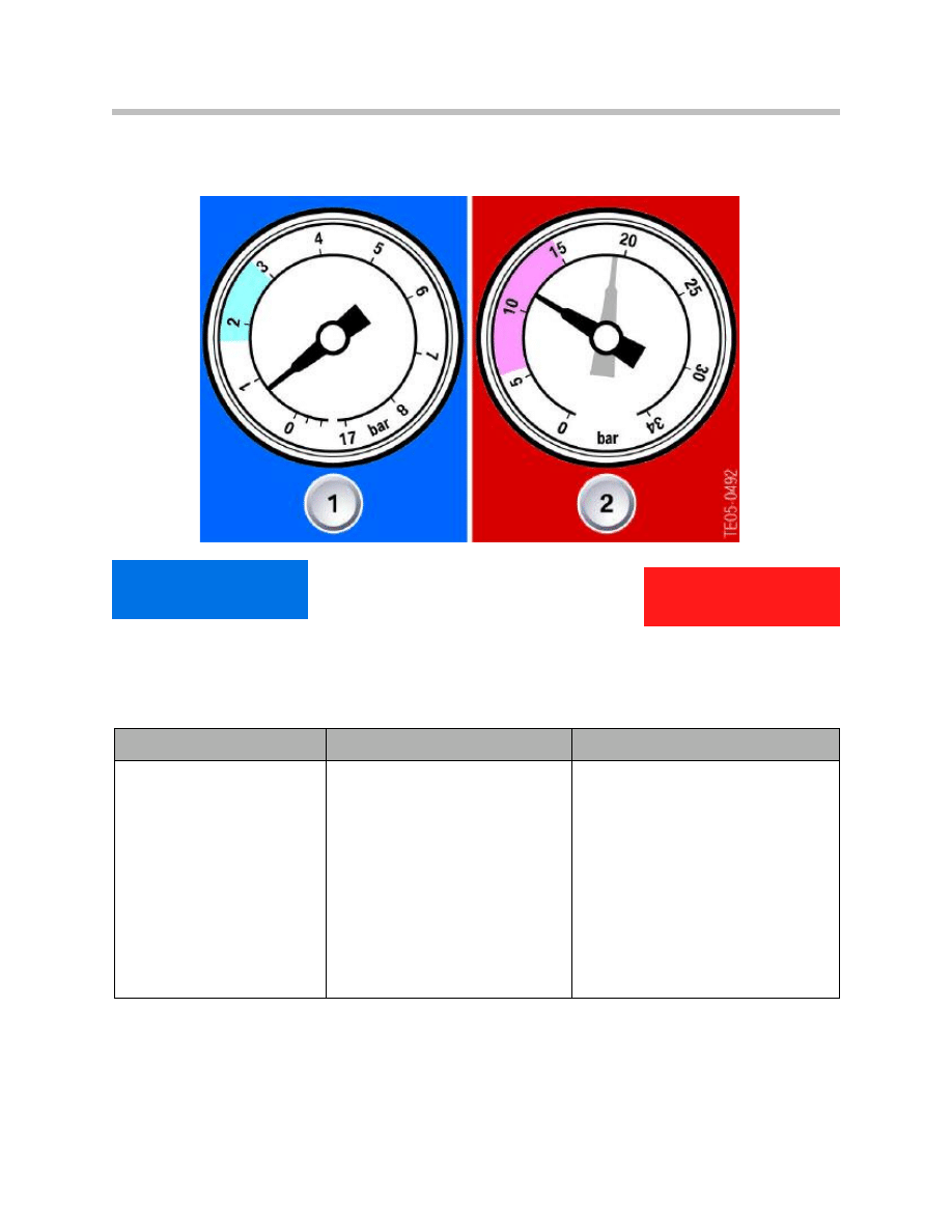
1 = Low pressure - normal to too low
2 = High pressure - normal to too high
Outlet Temperature Initially Cold then Warm
Symptoms
Possible faults
Repair
• Outlet temperature is initially
cold but then warm
• Evaporator/expansion valve
partly ices up and then thaws
again.
• High pressure increases, low
pressure drops to vacuum
range.
• Evaporator ices up before
the compressor is switched
off.
• Slow compressor switching
cycles.
Moisture in refrigerant circuit.
Recycle and Evacuate the system,
replace the dryer and recharge.
Temperature sensor for evapora-
tor defective.
Check evaporator temperature sen-
sor and replace if necessary.
Faulty pressure sensor or signal.
22 psi
to Vacuum
160-260 psi
26
Air Conditioning Service and Diagnosis
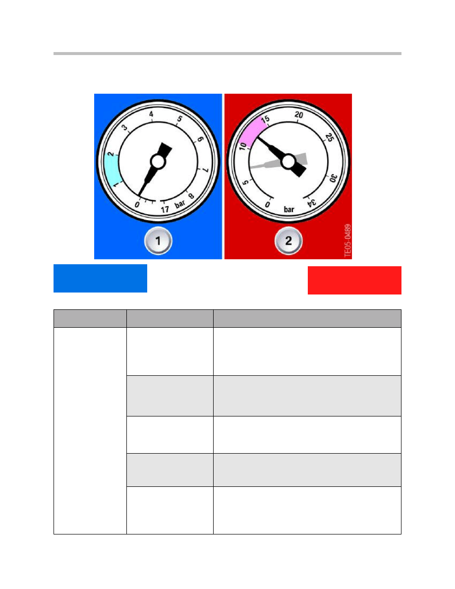
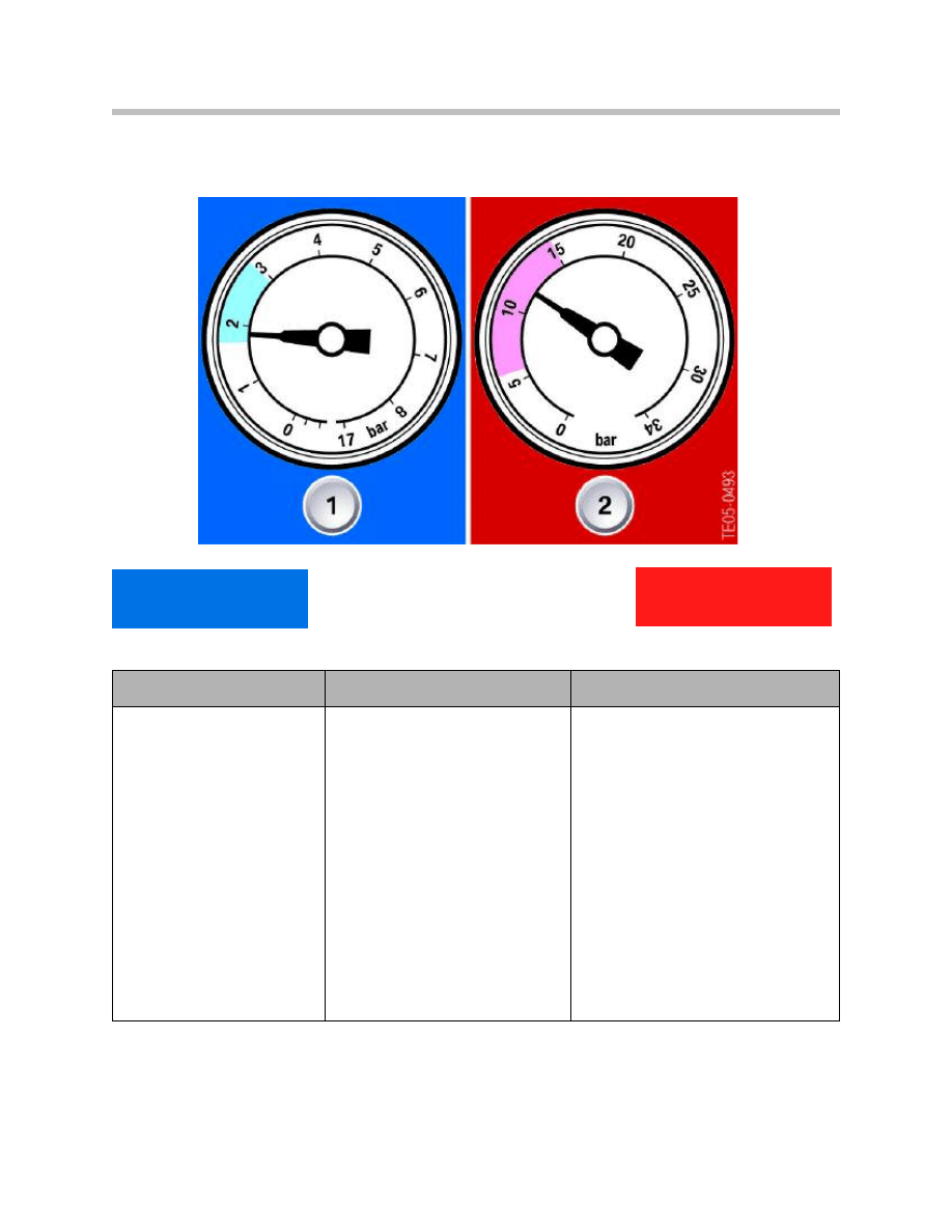
Outlet Temperature Not Cold
1 = Low pressure - too low
2 = High pressure - normal to too low
Symptoms
Possible faults
Repair
• Outlet tempera-
ture not cold
enough "only a lit-
tle cool but not
really cold".
Low refrigerant refriger-
ant in the system.
Evacuate system, compare amount of refrigerant
removed to required system capacity. Check for leaks,
correct and recycle and recharge refrigerant to specific
level.
System leaks.
Check for leaks and repair them, replace the compo-
nent in question. Recycle, recharge the system to spec-
ifications and re-check.
Failed expansion valve.
Replace expansion valve and dryer, recycle, evacuate
and recharge the refrigerant to specifications and leak
test.
Defective compressor.
Replace the compressor, receiver dryer, evacuate,
recharge to specifications and leak test.
Partial blockage of the
receiver dryer.
Recycle refrigerant, replace the dryer, evacuate the sys-
tem, recharge to specification and leak test.
Low
to Zero psi
100-180 psi
27
Air Conditioning Service and Diagnosis
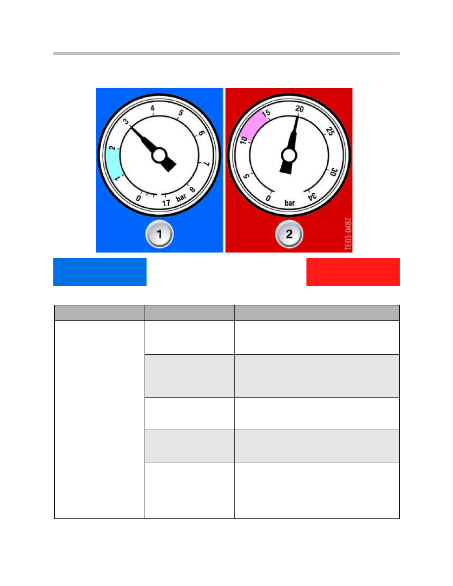
Outlet Temperature Cool but Not Cold
1 = Low pressure - too high
2 = High pressure - too high
Symptoms
Possible faults
Repair
• Outlet temperature cool
but not cold.
• Low side pipes hot to
the touch.
Air in the system.
Leak test, replace dryer, evacuate, recharge to
specifications and retest for leaks.
Too much refrigerant in
the system.
Recycle the refrigerant, evacuate the system
and recharge to specifications.
Condenser blockage/dirty
fins.
Check condenser fins for debris or damage
and correct.
Condenser fan is not
cooling.
Check operation of condenser fan (fuse, relay,
wiring, motor, stiff movement) and correct.
Expansion valve does not
close.
Check installation and operation of temperature
sensor, then replace expansion valve and dryer,
Recycle, recharge and leak test.
44 psi
295 psi
28
Air Conditioning Service and Diagnosis
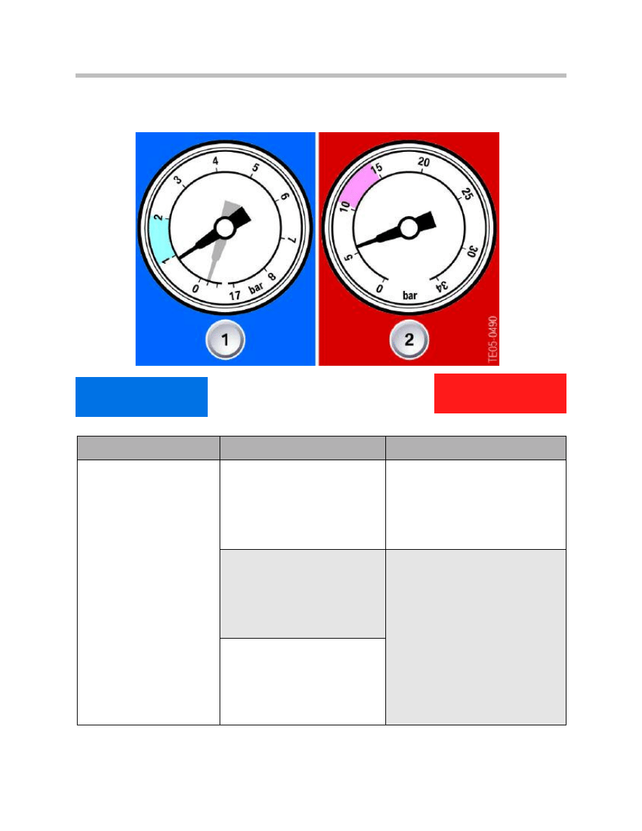
Not Cold with Visible Icing Near TEV
1 = Low pressure - too low
2 = High pressure - too low
Symptoms
Possible faults
Repair
• Outlet temperature not
cold enough "only a little
cool and not really cold".
• Low pressure may drop
into vacuum range.
• Visible icing on refrigerant
lines from/to dryer.
Moisture in the system.
Leak test, recycle the refrigerant,
replace dryer, evacuate, recharge and
retest for leaks.
Expansion valve blocked/
does not open.
Check installation and operation of
temperature sensor. Isolate blockage.
Recycle refrigerant, replace expan-
sion valve and or receiver dryer.
Evacuate, recharge to specifications
and leak test.
Filter dryer clogged, acts as throt-
tle, refrigerant expands in line
before expansion valve.
15 psi
to Vacuum
80 psi
29
Air Conditioning Service and Diagnosis
Note: If metal chips are found, clean entire system (e.g. blow out with pure
nitrogen!) and replace dryer.
Not Cold with Loud Compressor Operation
1 = Low pressure - too high
2 = High pressure - too low
Symptoms
Possible faults
Repair
• Outlet temperature insuffi-
ciently cold "not cold
enough".
• Compressor is loud.
• Reduced compressor out-
put.
Compressor drive belt slipping.
Check for correct tension of drive
belt and replace belt if necessary.
Magnetic clutch of compressor
defective or incorrectly set air
gap/clearance.
Check operation of magnetic clutch,
temperature/pressure switches,
wiring, fuse / relay, control unit),
adjust air gap if necessary.
Compressor may be mechanically
defective.
Replace compressor,
charge the system to specifications
and check for proper operation.
44 psi
100 psi
30
Air Conditioning Service and Diagnosis
Not Cold with Visible Icing Near Dryer
1 = Low pressure - too low
2 = High pressure - normal to high
Symptoms
Possible faults
Repair
• Poor or no cooling perfor-
mance.
• Visible condensation or
icing on lines or on compo-
nent.
Blockage on high pressure side,
generally in dryer.
Isolate the blockage, recycle the
refrigerant.
Locate and repair blockage, replace
the dryer, recharge to specifications,
check for leaks and verify systems
operation.
12-15 psi
180-290 psi
31
Air Conditioning Service and Diagnosis
Not Cold with Compressor Frequent Cycling
1 = Low pressure - normal
2 = High pressure - normal
Symptoms
Possible faults
Repair
• Outlet temperature is
not cold enough ("only
a little cool but not
cold enough").
• Frequent compressor
switch-on cycles (short
operation and short
cut-out times).
Temperature sensor for evapora-
tor is defective switches incor-
rectly.
Check evaporator temperature
sensor.
Verify electrical connection and
replace if necessary.
28 psi
180 psi

Service Information
Condenser Service
The procedure in the condenser is divided into three operations.
In the first stage, the hot gaseous refrigerant at a temperature of about 60 to120°C com-
ing from the compressor at a pressure of 10 to 25 bar gives off its superheat to the out-
side air. The actual condensation takes place in the second phase where the refrigerant
has lost so much energy that it becomes liquid. In the third phase, further energy is taken
from the now liquid refrigerant. This state is referred to as refrigerant sub-cooling. This
phase also makes sure that no gas bubbles can form on the refrigerant’s way to the
expansion valve. The sub-cooling takes more heat away from the refrigerant than is nec-
essary for actual condensation. The sub-cooled refrigerant in the evaporator can absorb
a larger quantity of heat and thus increase the refrigerating capacity of the system. The
auxiliary fan arranged directly before the condenser ensures an effective supply of cooling
air. The refrigerant remains in the condenser at a high pressure of approx. 10-25 bar.
Approximately 80-90% of the condenser is used in the actual condensation process
where a temperature drop of 30 to 40°C occurs.
The following points must be observed when working on the condenser:
• The distance between the condenser and vehicle radiator must be as large
as possible.
• The condenser fins must not be bent or dirty.
• Ensure the auxiliary fan is operating correctly.
• A soiled condenser results in poor condensation and unnecessarily high
operating pressures.
Note: The sub-cooling of the refrigerant in the condenser enhances the
efficiency of the air conditioning system.
Evaporator Service
The evaporator functions as a heat exchanger in that thermal energy is taken externally
from the air and given off internally to the refrigerant. The most important factor is the
energy absorption by the refrigerant during the transition from the liquid to the gaseous
state. This transition requires a great deal of energy in the form of heat which is taken
from the air blown through the system of fins. The refrigerant cools down greatly while
the injection procedure ensures the pressure drops from 10-20 bar. to about 2 bar. The
refrigerant is evaporated at low pressure by the heat delivered from the passenger com-
partment with the use of a blower fan.
32
Air Conditioning Service and Diagnosis
The following points must be observed when working on the evaporator:
• The evaporator fins must not be dirty or bent. This would result in the growth of bac-
teria and odor.
• The evaporator fins must not ice up. If the evaporator does ice up, the fault will be in
the area of the evaporator temperature sensor. This situation may result in compres-
sor damage.
• The micro filter change intervals must be maintained to insure adequate air flow.
• The condensation water drain must not be clogged and water must drain off freely.
• The evaporator temperature sensor must be installed correctly.
Note: To treat bacteria and odor complaints, a special cleaning and treatment
procedures must be followed. SI 64 04 03 “A/C System Musty Odor”
can be found in TIS.
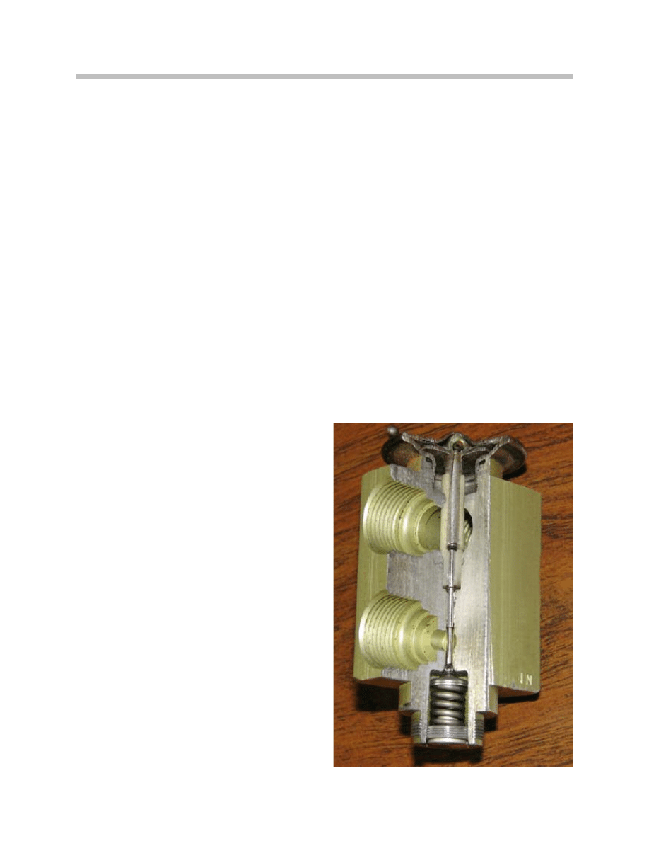
Expansion Valve Service
A block-valve design of expansion valve is used on current BMW A/C systems. The
refrigerant enters at the upper right inlet. At the left of the valve there is a capillary tube
filled with an inert gas that senses the temperature of the air coming into the housing
from the plenum.
When the air temperature in the plenum rises,
the pressure in the capillary tube increases.
This pushes down on a diaphragm and
pushrod assembly, which increases the size
of the orifice opening, allowing more refriger-
ant into the evaporator and providing more
cooling.
When plenum temperature falls, the pressure
in the capillary tube falls. The spring pushes
up on the pushrod, making the orifice open-
ing smaller; less refrigerant is allowed into the
evaporator, allowing less cooling.
Refrigerant from the outlet of the evaporator
passes through the bottom left opening of the
block valve.
33
Air Conditioning Service and Diagnosis

When the pressure at the evaporator outlet is high, this increases the pressure needed by
the capillary tube to open the valve. Less refrigerant is provided to the evaporator (to pre-
vent the evaporator from being flooded).
When pressure at the outlet end of the evaporator is lower, less pressure is exerted on the
bottom of the diaphragm. The diaphragm pushes down on the pushrod, allowing more
refrigerant into the evaporator.
The following points must be observed when working on the expansion valve:
• Very little refrigerant flow through the evaporator will result in poor AC output.
• Too much refrigerant flow will flood the evaporator and cause possible compressor
damage.
• The setting of the expansion valve must not be adjusted or varied (except for
instructions in the Service Information).
• The expansion valve must not be repaired.
• Seals must be replaced every time the pipes and hoses are released.
• It is imperative that an A/C system being serviced be evacuated for a minimum of
30 minutes or more in order to remove any possible moisture trapped within.
Note: If moisture gets into this system, it may freeze and clog the expansion
valve. The A/C system may operate normally for a while, then stop cool-
ing. Then, as system temperature increases, the ice melts. The system
works again for a while, until moisture freeze-up causes it to stop again.
Compressor Service
The function of the compressor is to pump the refrigerant along the system. As the
gaseous refrigerant exits the evaporator, it is pulled into the compressor by suction where
it is compressed and superheater and then pumped along to the condenser. Liquid
refrigerant in the compressor causes noise complaints and internal damage. There are
currently three methods of compressor control and two types of compressors depending
on the vehicle or equipment option. (See Compressor Operation)
Typical compressor service points to remember:
• When troubleshooting a noisy compressor complaint, make sure the noise is present
only when the clutch is engaged.
• If it is present when the clutch is not engaged, remove the compressor drive belt and
check again.
• If the noise continues, it is not related to the compressor.
• If removing the drive belt reduces or eliminates the noise, check the torque of the
compressor and bracket mounting bolts.
34
Air Conditioning Service and Diagnosis

• Check the belt tension and condition, and tensioner pullies which can produce
rattling noises that would sound like a defective compressor.
• A loose/slipping belt can cause noise.
• A belt that is too tight can damage the clutch/pulley bearings.
• If the compressor is noisy with the compressor clutch engaged, make sure the
system is charged with the correct amount of refrigerant.
• An over-charged system can cause compressor noise.
• If the A/C system is overcharged, the liquid refrigerant entering the compressor
can damage it.
• When troubleshooting a noisy compressor complaint, recover the refrigerant and
recharge the system with the correct amount.
• A failed compressor must be returned with the inlet and outlet ports sealed using
the plastic caps from the replacement compressor. Otherwise the “failed” compres-
sor will be damaged by moisture, and it will be impossible for Warranty to analyze it.
Compressors with plastic pullies:
• Avoid impact on the plastic pulley (through tools, contact with base).
• Send back damaged compressors only in original packaging.
Note: It is important to perform the following running-in procedure when
operating a new compressor for the first time.
Compressor Running-in Procedure
• Switch off air conditioning system.
• Set all air outlet nozzles on the instrument panel to "OFF".
• Start engine and allow idle speed to stabilize.
• Set blower capacity to min. 75% of the maximum blower capacity.
• Switch on air conditioning and allow to run for at least 2 minutes at idle speed. Risk
of damage at higher speed! (Refer to BMW Diagnostic Equipment Service
Functions for more detailed instructions)
Note: When replacing a compressor you must follow the instructions on refill-
ing the refrigerant oil. For details on compressor replacement and oil
capacities are found in the Operating Fluids Information in TIS.
35
Air Conditioning Service and Diagnosis
Document Outline
- Main Menu
- Principles of Heating and Refrigeration
- Refrigerant
- Engine Cooling/Heating System
- A/C System and Components
- Climate Control Components
- Climate Control Systems and Functions
- Air Conditioning Service and Diagnosis
- Future Technology
- Glossary
Wyszukiwarka
Podobne podstrony:
Basic AC Generators and Motors
SHSBC335 SERVICE?CS AND GPMs
Next Gen VoIP Services and Applications Using SIP and Java
Anatomy and diagnosis
2007 2 MAR Clinical Pathology and Diagnostic Techniques
Basic AC Generators and Motors
Gordon Dickson Dragon 07 The Dragon and the Gnarly King (v1 2) (lit)
04 AC System and Components
Jiddu Krishnamurti 07 The First And Last Freedom
Jackie Nacht Holiday Jobs That Don t Suck 07 The Firecracker and the Rocket
Clinical and diagnostic aspects ofencephalopathy associated with autoimmunethyroid disease (or Hashi
07 Ambulance Service
think city service and warranty manual
islcollective worksheets beginner prea1 elementary school speaking weather ac eather and countries 2
2007 2 MAR Clinical Pathology and Diagnostic Techniques
Barb & J C Hendee Noble Dead 07 In Shade and Shadow (v5 0)
więcej podobnych podstron