HOW TO BUILD A CHISPITO WIND GENERATOR
NOTE: THE MAKE MAGAZINE ARTICLE SHOWS THE BLADES BEING CUT FOR A CW
ROTATION. IF YOU ARE USING THE TREADMILL MOTOR MENTIONED IN THE
ARTICLE PLEASE CUT THE BLADES PER THE WEBSITE INSTRUCTIONS.
INTRODUCTION
Wind power is abundant, clean,
inexpensive and easy to do. It is our
belief that anyone can be in control of
where his or her electricity comes from.
There is nothing more rewarding and
empowering than making a wind
powered generator from scrap
materials. Most of the tools and
materials in this manual can be found in
your local hardware shop or junk pile.
We highly recommend you search your
local dump and/or junkyards for the
materials required. If you live in a city,
do a search on freecycle.org for salvaged
parts.
Safety should be our highest priority. Human life is more important than electricity, so
please follow any and every
safety guideline
you come across. Wind generators can be
very dangerous, with fast moving parts, electrical sparks, and violent weather
conditions.
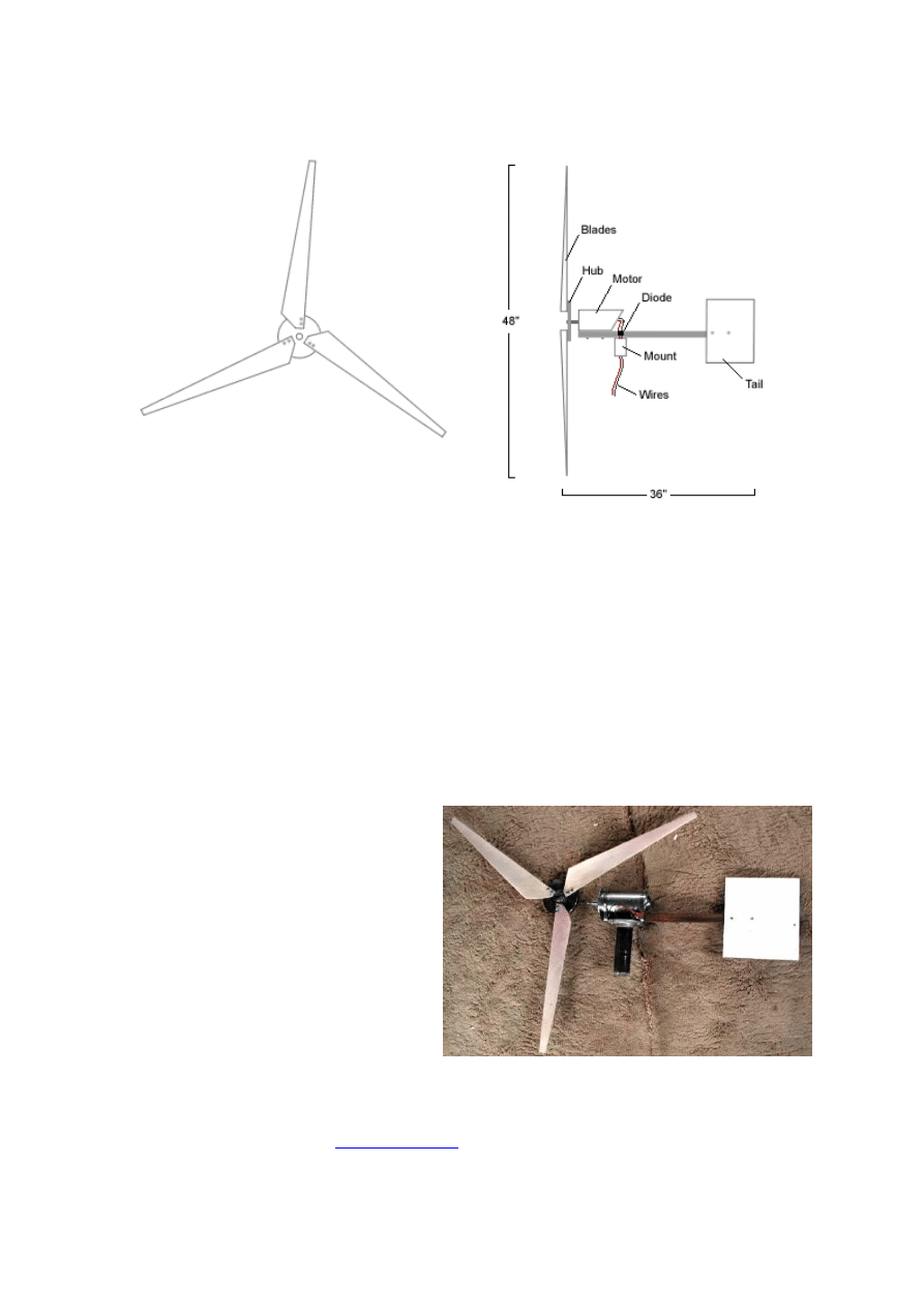
The Chispito Wind Generator was designed to be simple and efficient with fast and easy
construction. There are no limits to what you can do with wind power. For more
information and inspiration on wind generator construction, please visit otherpower.com
SUPPLIES
This manual is based on using a 260 VDC, 5 A continuous duty Treadmill Motor with a 6
inch threaded hub. These motors are available for under from most
motor surplus
stores
. We are getting about 7 amps in a 30 mph wind. In other words, it is a simple,
cheap little machine to get you started.
You may use any other simple permanent magnet DC motor that returns at least 1 V for
every 25 rpm and can handle upwards of 10 amps. If you do, there will be certain
changes to this supply list (for example, you will have to find a hub - a circular saw blade
with a 5/8" shaft adaptor will work).
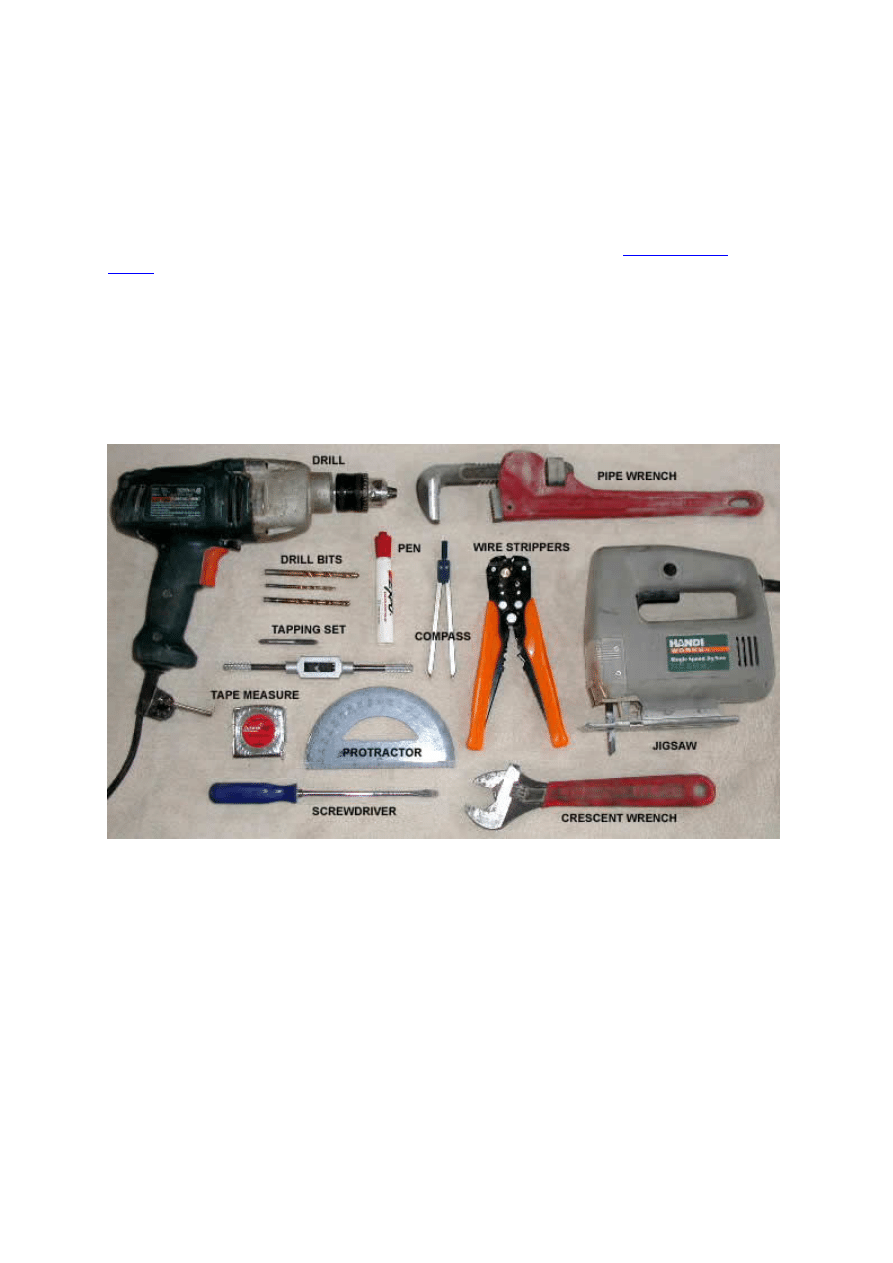
Tools
•
Drill
•
Drill Bits (7/32", ¼", 5/16")
•
Jigsaw with a metal blade
•
Pipe Wrench
•
Flat Head Screwdriver
•
Crescent Wrench
•
Vise and/or Clamp
•
Wire Strippers
•
Tape Measure
•
Marker Pen
•
Compass + protractor
•
¼" #20 Thread Tapping Set
•
An extra person helps a lot!
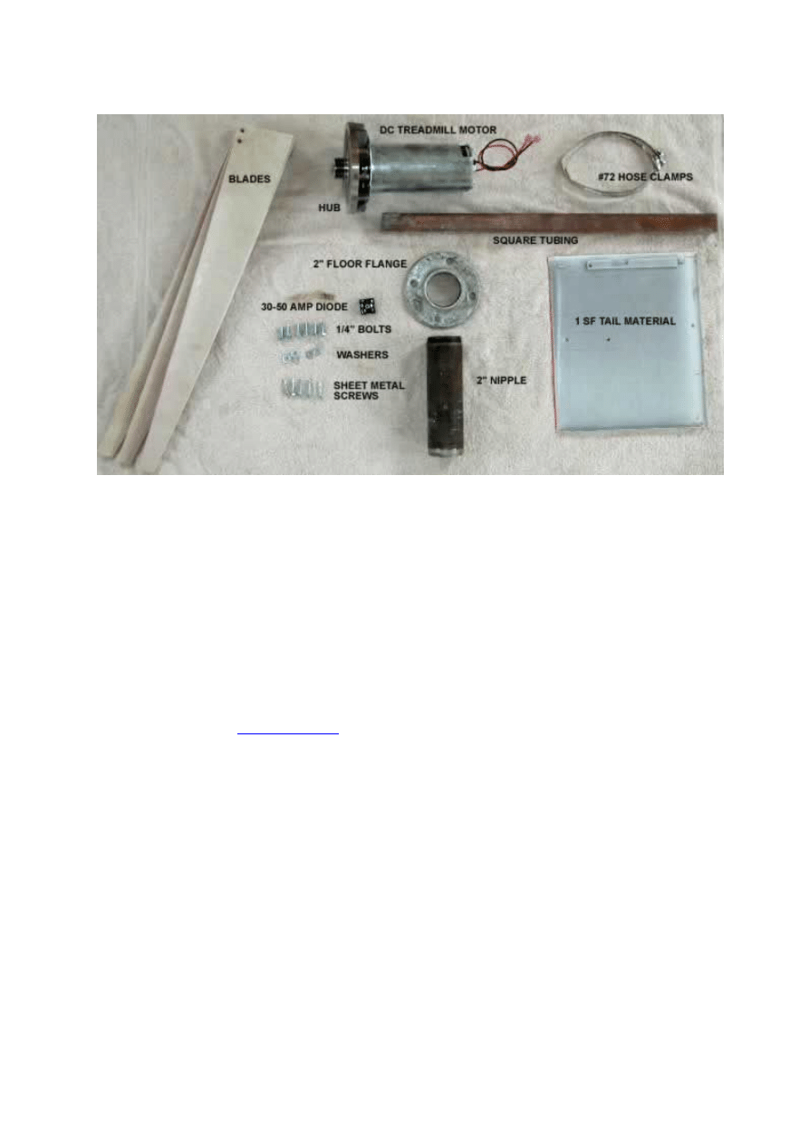
Materials
Mount
•
36" of 1" Square Tubing
•
2" Floor Flange
•
2" X 4" Nipple
•
3 X 3/4" Self-tapping Screws
NOTE: if you have access to a welder, you can weld a 4” section of 2” pipe onto your
square tubing instead of using the flange, nipple and sheet metal screws.
Motor
•
260 VDC, 5 A continuous duty Treadmill Motor with a 6 inch threaded hub
•
30 - 50 Amp
Blocking Diode
(one-way)
•
2 x 5/16” x ¾” Motor Bolts
•
3" X 11" PVC Pipe
Tail
•
1 sqft (approx) lightweight material (metal)
•
2 X ¾" Self-tapping Screws
Blades
•
24" length of 8" PVC Pipe (if it is UV resistant, you will not need to paint it)
•
6 X ¼" X 20 Bolts
•
9 x ¼" washers
•
3 sheets A4 paper and tape
PREPARATION
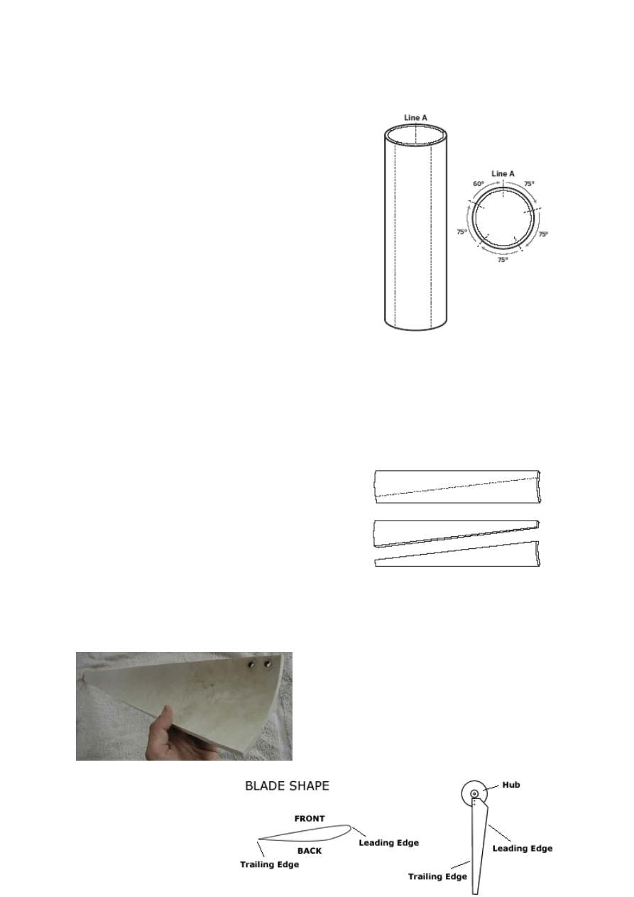
Cutting Blades - makes 9 blades (or 3 blade sets)
and a thin waste strip.
1.
Place the 24" Length of PVC pipe and square
tubing (or other straight edge) side by side on
a flat surface. Push the pipe tight against the
tubing and mark the line where they touch.
This is Line A.
2.
Make a mark near each end of Line A, 23"
apart.
3.
Tape 3 sheets of A4 paper together, so that
they form a long, completely straight piece of
paper. Wrap this around the section of pipe at
each of the two the marks you just made, one
then the other. Make sure the short side of the
paper is straight along Line A and the paper is
straight against itself where it overlaps. Mark
a line along the edge of the paper at each
end. Call one Line B and the other Line C.
4.
Start where Line A intersects Line B. Going left
around Line B, make a mark at every 145 mm. The last section should be about
115 mm.
5.
Start where Line A intersects Line C. Going right around Line C, make a mark at
every 145 mm. The last section should be about 115 mm.
6.
Mark each line using a straight edge.
7.
Cut along these lines, using the jigsaw, so that you have 4 strips of 145 mm and
one strip about 115 mm.
8.
Take each strip and place them with the
inside of the pipe facing down.
9.
Make a mark at one end of each strip 115
mm from the left edge.
10.
Make a mark at the other end of each strip
30 mm from the left edge.
11.
Mark and cut these lines, using the jigsaw.
12.
Place each blade with the inside of the pipe
facing down.
13.
Make a mark along the angled line of the
blade, 3" from the wide end.
14.
Make another mark on the wide end of the blade, 1" from the straight edge.
15.
Connect these two marks and cut along the line. This prevents the blades
interfering with the others' wind.
Sanding the Blades
You should sand the
blades to achieve the desired
airfoil. This will increase the efficiency of the blades, as well as making them quieter.
The angled (leading) edge wants to be rounded, while the straight (tailing) edge wants
to be pointed.
Any sharp corners should be slightly rounded to cut down on noise.
Cutting Tail
The exact dimensions of the tail are not important. You want about one square foot of
lightweight material, preferably metal. You can make the tail any shape you want, so
long as the end result is stiff rather than floppy.
Drilling Holes in Square Tubing - using the 5/16” drill bit
1.
Place the motor on the front end of the square tubing, so
that the hub part hangs over the edge and the bolt holes of
the motor face down.
2.
Roll the motor back so you can see the bolt holes, and mark
their position on the square tubing.
3.
Drill a 5/16” hole at each mark all the way through the
square tubing.
Floor Flange Holes
This will be dealt with in the assembly section of this manual, as these holes are what
determine the balance.
Drilling Holes in Blades - using the ¼" drill bit
1.
Mark two holes at the wide end and along the straight edge of each of the three
blades. The first hole should be 3/8 " from the straight edge and ½ " from the
bottom. The second hole should be 3/8 " from the straight edge and 1 ¼" from
the bottom.
2.
Drill these 6 holes.
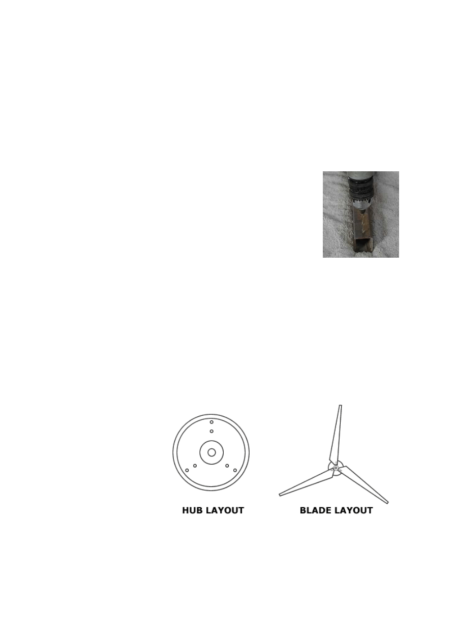
Drilling and Tapping
Holes in Hub - using the
7/32" drill bit and ¼" tap
1.
The Treadmill motor
comes with the hub
attached. To take it
off, hold the end of
the shaft (which
comes through the
hub) firmly with
pliers, and turn the
hub clockwise. This
hub unscrews
clockwise, which is
why the blades turn counter-clockwise.
2.
Make a template of the hub on a piece of paper, using a compass and protractor.
3.
Mark 3 holes, each of which is 2 3/8" from the center of the circle and equidistant
from each other.
4.
Place this template over the hub and punch a starter hole through the paper and
onto the hub at each hole.
5.
Drill these holes with the 7/32" drill bit.
6.
Tap the holes with the ¼" x 20 tap.
7.
Bolt the blades onto the hub using the ¼"
bolts. At this point, the outer holes have not
been drilled.
8.
Measure the distance between the straight
edge of the tips of each blade. Adjust them so
that they are all equidistant. Mark and punch
each hole on the hub through the empty hole
in each blade.
9.
Label the blades and hub so that you can
match which blade goes where at a later
stage.
10.
Remove the blades and then drill and tap these outer three holes.
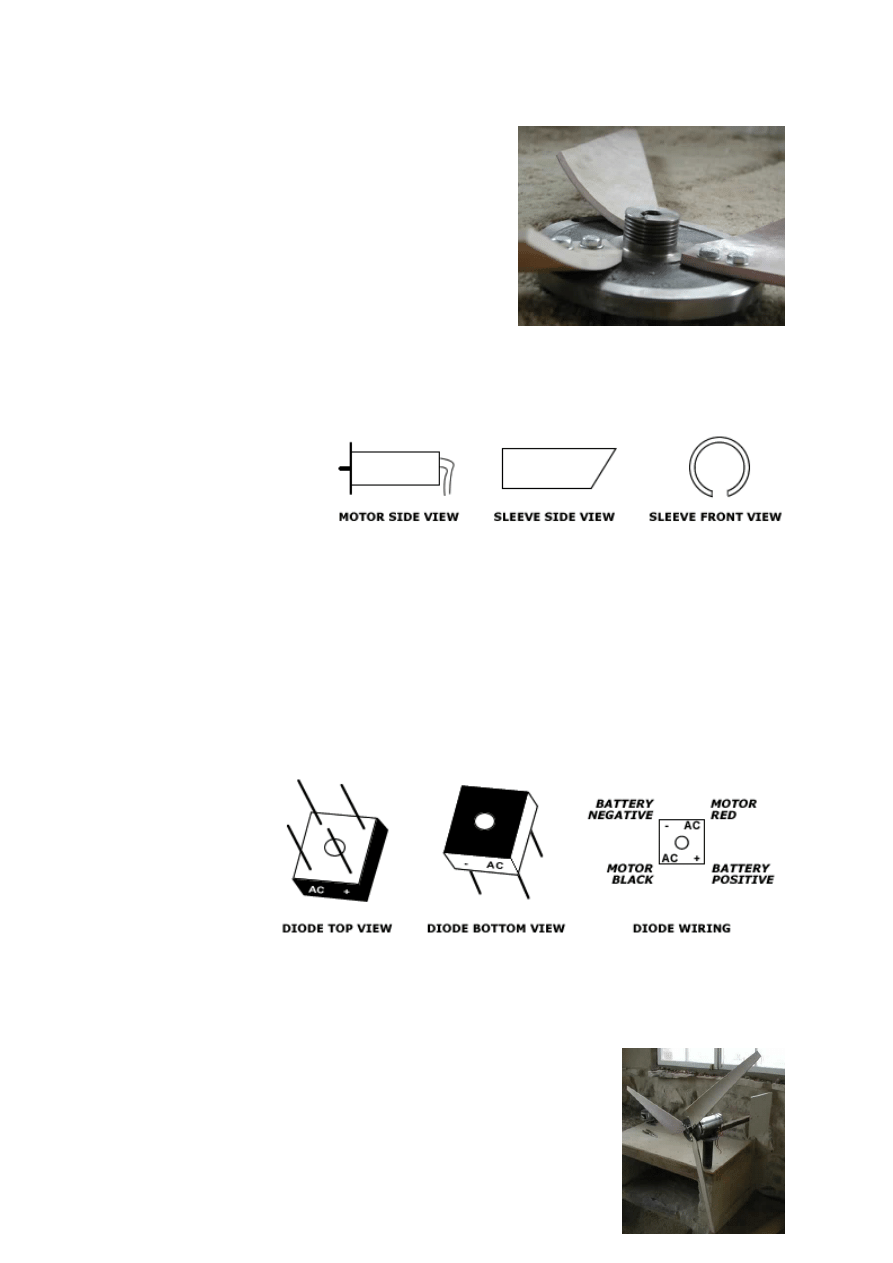
Making a Protective
Sleeve for the Motor
1.
Draw two straight
lines, about ¾” apart,
along the length of
the 3” x 11” PVC
Pipe. Cut along these
lines.
2.
Make a 45º cut at the end of the pipe.
3.
Place needle nose pliers inside the strip that has been cut out, and pry the pipe
apart.
4.
Making sure the bolt holes of the motor are centered in the middle of the missing
strip of PVC pipe, push the motor into the pipe. An extra person will make this a
lot easier.
ASSEMBLY
1.
Place the motor on top of the square tubing and bolt it in, using the two 5/16” x
¾” bolts.
2.
Place the
diode on the
square tubing,
about 2”
behind the
motor, and
screw it into
position using
the self-
tapping metal
screw.
3.
Connect the black wire coming out of the motor to the positive incoming terminal
of the diode (Labeled AC on the positive side).
4.
Connect the red wire coming out of the motor to the negative incoming terminal
of the diode (Labeled AC on the negative side).
5.
Center the tail over the square tubing, at the back end.
Clamp your tail onto the side of the square tubing.
6.
Using 2 self-tapping screws, screw the tail in place.
7.
Place each blade on the hub so that all the holes line up.
Using the ¼" bolts and washers, bolt the blades to the
hub. For the inner three holes, use two washers per bolt, one on each side of the
blade. For the outer three holes, just use one washer next to the head of the bolt.
Tighten.
8.
Hold the end of the shaft of the motor (which comes through the hub) firmly with
pliers, and turn the hub counterclockwise until it tightens and stops.
9.
Screw the nipple tightly into the floor flange using a pipe wrench.
10.
Clamp the nipple in a vice so that the floor flange is
facing up and level.
11.
Place the square tubing (and everything that is on it) on
top of the floor flange and move it so that it is perfectly
balanced.
12.
Through the holes of the floor flange, mark the square
tubing at the point of balance.
13.
Drill these two holes using a 5/32" drill bit. You will
probably have to take off the hub and tail to do this).
14.
Attach the square tubing to the floor flange with two
sheet metal screws.
For a longer life span of your wind generator, you should paint the blades, motor sleeve,
mount and tail.
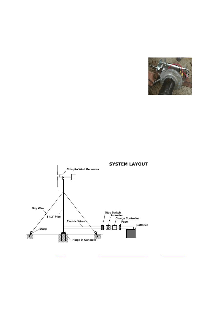
ADDITIONAL INFORMATION
Use of Chispito Wind Generator
You will need a
tower
, wire, ammeter,
charge controller/regulator
, and a
battery bank
for your Chispito Wind Generator.
Tower
The tower is one of the most important components in your wind generator system. It
must be strong, stable, easily raised and lowered, and well anchored. The higher your

tower is, the more wind your generator will be exposed to. Guy wires must be placed at
least every 18 feet of tower height. Guy wires must be anchored to the ground at least
50% of the height away from the base. For full tower instructions, please refer to our
Tower How-To
.
Wyszukiwarka
Podobne podstrony:
How to Build Pyramids and other Orgone Generators
piggott how to build a wind turbine
How To Build Your Real Estate Business & Generate Leads Realtors Agents Buyer Reps
ENERGY POWER WATER Electricity How to Build a Waterwheel Generator (ebook Home Power Diy 185336
O'Reilly How To Build A FreeBSD STABLE Firewall With IPFILTER From The O'Reilly Anthology
How to build a Raised Formal Pool
How to build a Retaining Wall
How to build an arbor id 206318 Nieznany
How to build a solar icemaker
Distillation How to build an Electric Still
HOW TO BUILD A DECK jak zbudowac taras
How to build a USB device with PIC 18F4550 or 18F2550 (and the microchip CDC firmware)
How To Build an Acid Alkaline Water Charger health healing search for [!B!]
How to Build a Walk Through Garden Pergola
Bazooka How To Build Your Own
O'Reilly How To Build A FreeBSD STABLE Firewall With IPFILTER From The O'Reilly Anthology
How to build a Raised Formal Pool
Box How To Build A Firewood Box
więcej podobnych podstron