
Thermo Top
Tele Thermo Top
from serial no. 300 000 onward
Thermo Top T
Tele Thermo Top T
from serial no. 300 000 onward
Auxiliary Heater
Type BW 50 (Petrol)
Type DW 50 (Diesel)
Operating Instructions must be read before
attempting to start up the heater.
8/2000
Water Heater
Installation instructions

Table of contents
Page
Installation instructions
1
Legal Provisions
1
Installation Location
2
Installation example
Thermo Top
4
Fuel Installation
5
Combustion Air Supply
5
Insert Plate
6
Exhaust Gas Pipe
6
Electrical Connections
7
wiring diagram
9
Initial Operation
10
Troubleshooting
11
Versions
12
Technical Data
13
Webasto Service Phone Line
14
Thermo Top
I

Installation instructions
Legal Provisions for Installation
For testing the heater in accordance with articles 19, 20 or
21 of the StVZO the following regulations are primarily to
be observed (art. 22a StVZO):
NOTE:
These provisions are binding within the scope of the
StVZO and should also be observed in countries
where no special regulations are in effect!
Within the scope of the StVZO (German Road Licensing
Regulations) “General Design Certifications” have been
granted by the Federal Office for Motor Traffic for the
Thermo Top water heaters with the following design ap-
proval numbers:
~
S 238 for the
Thermo Top - Patrol heating device,
type
BW
50
~
S 239 for the
Thermo Top - Diesel heating device,
type
DW
50
The installation of the heaters must be performed in ac-
cordance with these Installation Instructions. The installa-
tion must be checked
a) upon the homologation of the vehicles in accordance
with § 20 StVZO
b) upon any individual test in accordance with
§ 21 StVZO, or
c) upon any examination in accordance with § 19 StVZO
by a registered expert or examiner for motor traffic, an
expert for automotive vehicles, or any other authorised
official, in accordance with paragraph 4 of
Appendix VIIIb to the StVZO
and in the case of item c) the proper installation must be
certified on the approval certificate contained on the de-
sign certification stating the following:
- vehicle manufacturer
- vehicle type and
- vehicle identification number
The effectiveness of the design certification (homologa-
tion) is dependent on this certificate. The approval certifica-
tion is to be kept in the vehicle.
The year of the initial operation must be durably marked
on the type plate of the heater by the installer by removing
the years that do not apply.
Extracting the combustion air from the interior of the
vehicle is not permissible.
The exhaust pipe must be so mounted that its discharge
opening points downward, sideways or, in the case of rout-
ing the exhaust pipes on the underside of the bottom of the
vehicle, their discharge opening must be positioned near
the lateral or rear edge of the driver’s cab or vehicle.
Exhaust pipes must be routed in such a way that exhaust
gases cannot penetrate the interior of the vehicle. The
function of any parts of the vehicle essential for its oper-
ation must not be impaired.
The openings of the combustion air inlet and exhaust gas
outlet must be so designed that a spherical object of 16
mm diameter cannot be introduced.
Electric lines, switchgear and controlgear of the heater
must be so arranged in the vehicle that their proper func-
tion cannot be impaired under normal operating conditions.
For the routing of fuel lines and the installation of addi-
tional fuel tanks articles 45 and 46 of the StVZO are to be
adhered to. The most important excerpts therefrom are as
follows:
Fuel lines are to be designed in such a way that they re-
main unaffected by torsional stresses in the vehicle, en-
gine movement and the like. They must be protected
against mechanical damage. Fuel-carrying parts are to be
protected against excessive heat and are to be arranged
such that any dripping or evaporating fuel can neither col-
lect nor be ignited by hot components or electrical equip-
ment.
The heater must not be installed in passengers areas.
The operating state of the heater at any given time - i.e. at
least an indication as to whether it is “on” or “off” - must be
easily recognizable.
The installation of components that are not of an approved
type will lead to the invalidation of the General Design Cer-
tification of the heater and thus the General Operating Per-
mission of the vehicle. The same applies to improperly per-
formed repairs or those where other than genuine replace-
ment parts were used.
Use of the Water Heater
The Webasto
Thermo Top water heater in conjunction
with the vehicle heating system is used for
- heating the driver’s cab,
- defrosting the vehicle’s windows as well as
- preheating water-cooled engines.
The water heater operates independently of the vehicle en-
gine and is connected to the cooling system, the fuel sys-
tem and the electrical system of the vehicle.
Thermo Top
1
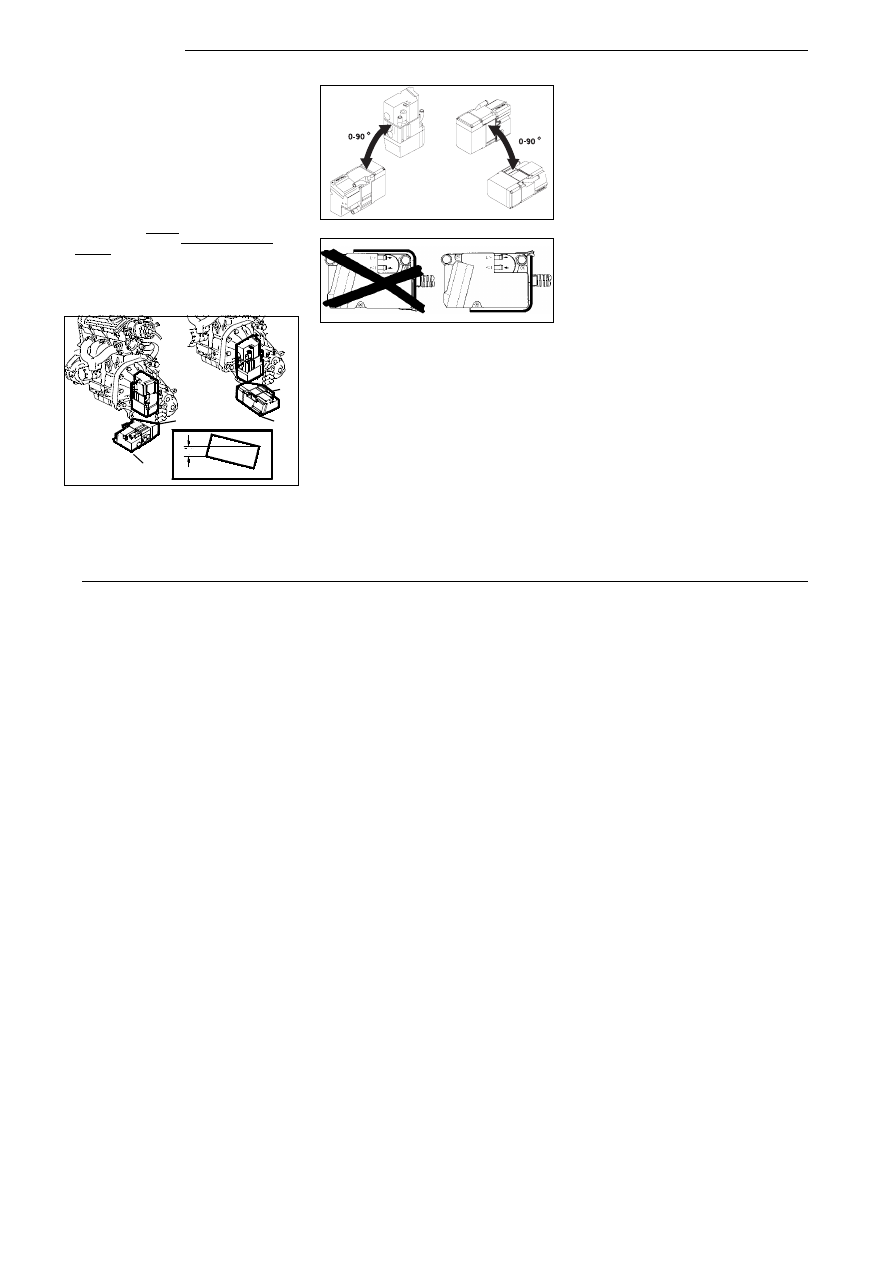
Installation Location
Preferably, the heater should be installed in the engine
compartment, the splash-water protected areas of the front
fenders or at the splashboard.
If the heater cannot be installed in the aforementioned loca-
tions it may also be installed:
- in upright position in front of the gearbox (partly
covered, see Fig. 1) provided the fuel supply system is
not located in front of the engine, any auxiliary equip-
ment or the gearbox.
-
in inclined position in front of the gearbox (see illus-
tration) provided point “A” is located below the lower
edge of the gearbox and at least 25 mm above
point “B”. This ensures that the heater can slide
underneath the gearbox in the case of an accident.
- in accordance with vehicle-specific Webasto installation
instructions which are to be presented to the officially
registered expert when the installation is being in-
spected.
The heater should be installed at a level as low as possible
so as to ensure automatic venting of heater and circulating
pump. This is of special importance since the circulating
pump is not of the self-priming type.
Note:
The heater must not be installed on the support plate in a
hanging position.
CAUTION:
The heater must not be installed in the following places:
- in the immediate vicinity of or above hot parts
- in the direct splash water area of the wheels
- in front of the engine block or the engine units
- in engine compartments which are open at the bottom,
below the wheel center (i.e. in each permissible mount-
ing position the bottom of the heater must be located
above the wheel center).
Caution:
The openings of the water connecting branches must not,
in any installation position, point in downward direction.
Nameplate
The type plate must be located at a place where it is pro-
tected against damage and must be easily accessible
once the heater has been installed (or a nameplate dupli-
cate is to be used).
The year not applicable is to be removed from the type
plate.
A
B
A
B
A
B
min 25
Fig. 1:
Installation location in front of the gearbox
Fig. 2:
Mounting position
Fig. 3:
Mounting position
Thermo Top
2
Connection to the Vehicle Cooling System
The heater is to be connected to the vehicle cooling sys-
tem in accordance with Figs. 4, 5 and 6. The coolant sys-
tem capacity must be at least 4 liters.
As a rule, the water hoses (pipes) supplied by Webasto
are to be used. If not, the hoses must at least conform to
DIN standard 73411. The hoses are to be laid
without any
kinks and - for proper venting - should be pitched upward,
if possible. Hose connections must be secured against slip-
ping off by means of hose clamps.
NOTE:
The hose clamps at the heater must be mounted between
the flared neck of the pipe and the heater.
The hose clamps must be tightened to a torque of 2,0 +
0,5 Nm.
Before the heater is operated for the first time or after cool-
ant has been replaced it must be ensured that the cooling
system is properly vented. Heater and piping should be so
installed as to ensure static venting.
Insufficient venting can result in a failure during heating
operation due to overheating.
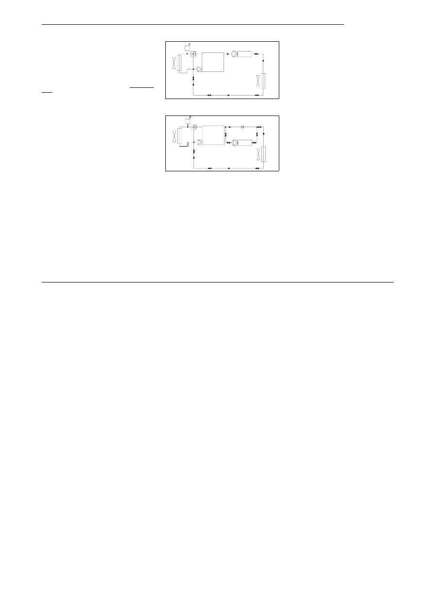
Legend for Fig. 4 and 5:
1 Expansion
tank
2 Thermostat
3 Engine
4 Check
valve
5 Heater
6 Heat exchanger
7 Radiator
1
3
5
6
2
7
Fig. 4:
Integration into engine/cooling water circuit
“Inline-Integration”
1
3
4
5
6
2
7
Fig. 5:
Integration with check valve
Thermo Top
3
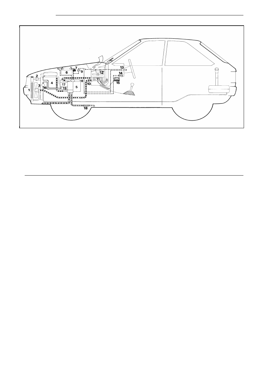
Fig. 6:
Installation example of heater
Thermo Top in a passenger car
1
Radiator
2
Cooling water thermostat
3
Water pump (of car engine)
4
Standard equipment engine
5
Water heater
6
Battery
7
Fuse holder
8
Control unit (in heater)
9
Relay (for vehicle fan)
10
Regulating valve of vehicle heating
11
Heat exchanger, vehicle heating system
12
Vehicle heater fan
13
Vehicle heater fan switch
14
Fuse bank in the vehicle
15
Digital timer
16
Fuel pickup
17
Fuel pump (in heater)
18
Exhaust muffler, as required
19
Circulating pump (in heater)
Thermo Top
4
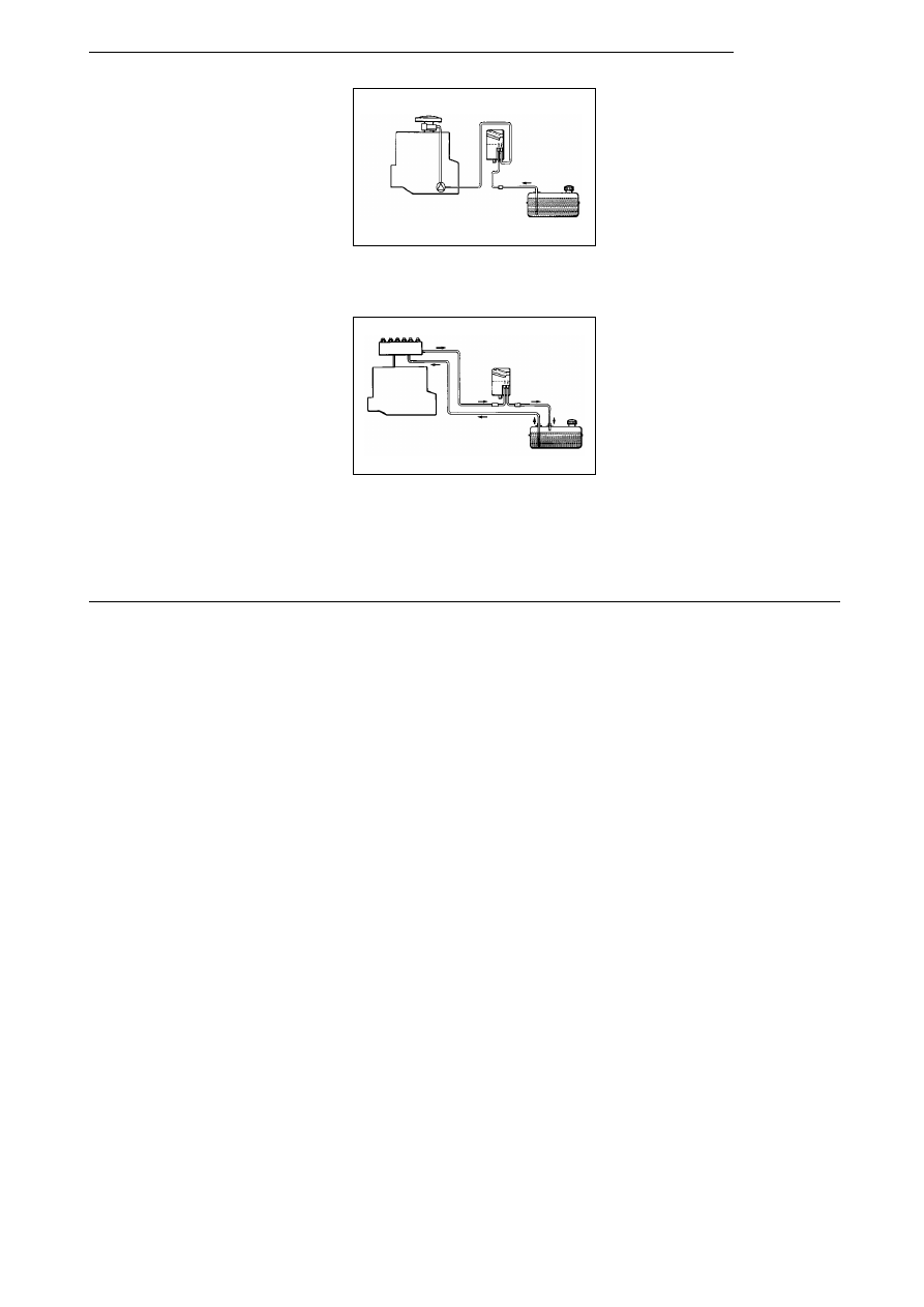
Fuel Installation
Fuel Supply
In the case of carburetor or injection engines equipped
with return line, the heater’s fuel supply circuit must be inte-
grated in the return line as shown in Fig. 8.
The direction arrows provided on the heater must be ob-
served.
In the case of carburettor engines without return line, the
fuel supply circuit of the heater must be integrated in the
flow line between vehicle fuel tank and pump as shown in
Fig. 7.
ANNOTATION
A fuel flow line can usually be identified by the in-line fuel
filter.
NOTE:
If the fuel system of the vehicle is equipped with a degass-
ing device, fuel extraction is to take place upstream of
same.
Fuel Lines
Only the special hoses supplied with the heater by We-
basto must be used as fuel lines between fuel connections
and heater. When using hoses, the joints are to be se-
cured using hose clamps. To prevent any sagging the fuel
line must be secured with clips.
Prior to cutting the fuel line open it must be clamped off or
a suitable vessel placed underneath the pipe.
Any fuel that may have leaked is to be removed from the
engine or heater prior to starting up the vehicle or heater
The fuel lines - not cut to length as yet - are to be con-
nected to the vehicle’s return line.
Keeping slack to a minimum, they are then to be routed
along any obstructing vehicle parts up to the fuel connec-
tions of the heater and the length thus obtained is to be
marked.
The fuel lines are to be cut off 35 cm longer than marked.
The excess length of the fuel lines of 35 cm is to be dis-
tributed evenly. The fuel lines are to be so fastened that
they will not be damaged by vehicle parts that may come
in contact with them.
The lines must be mounted in such a way that they are pro-
tected from mechanical damage (e.g. stones) and thermal
influence (e.g. exhaust pipe). If the fuel line is damaged
there is a danger of fire.
NOTE:
The hose clamps are to be tightened to a torque of 1.0 +
0.4 Nm.
Combustion Air Supply
Combustion air is to be drawn in from a location as cool as
possible and splash-proof via a combustion air line.
The combustion air line which is contained in the installa-
tion kit must not be extended.
It may be shortened to a min. of 500 mm.
The combustion air line may feature several bends (total of
270°, smallest bending radius 50 mm).
NOTE:
The combustion air line consists of an inside and outside
part.
Shorten combustion air line only at the end that is not pro-
vided with a fastening clip.
fuel pump
engine
carburator
Fig. 7:
Fuel Supply Circuit in the Single Line Sys-
tem (Carburetor Engine without Return Line)
“Inline Integration between Pump and Car-
buretor”
engine
injection system
flow pipe
return pipe
Fig. 8:
Fuel Supply Circuit in the Double Line Sys-
tem (Carburetor or Injection Motor with Re-
turn Pipe) “Inline Integration in Return Flow”
Thermo Top
5
Shorten combustion air line only at the end that is not pro-
vided with a fastening clip.
Prior to installing the heater make sure that the combus-
tion air intake connection has been mounted to the heater.
Under no circumstances must the combustion air be ex-
tracted from driver’s cabs or passenger compartments. If
the heater is installed in an enclosed housing a vent hole
of at least 3 cm
2
is required.
If the temperature in the installation housing exceeds the
permissible ambient temperature of the heater the vent
hole must be enlarged after consulting Webasto.
The combustion air intake opening must be so positioned
as to prevent any clogging due to contamination. It must
not point in the direction of travel.
When the heater is installed in the vicinity of the vehicle
tank in a common installation space, combustion air intake
must be from the outside of the vehicle and the exhaust
gas must be discharged to atmosphere. Appropriate cu-
touts must be splash-proof.
Support Plate
The support plate must be secured to the chassis or the in-
termediate support using at least 4 M6 screws.
It is mandatory that washers and spring lock washers be
used.
In the case of level chassis surfaces, the washers used
must be at least 22 mm in diameter.
No sheet-metal screws must be used to secure the heater
mounting plate (support plate).
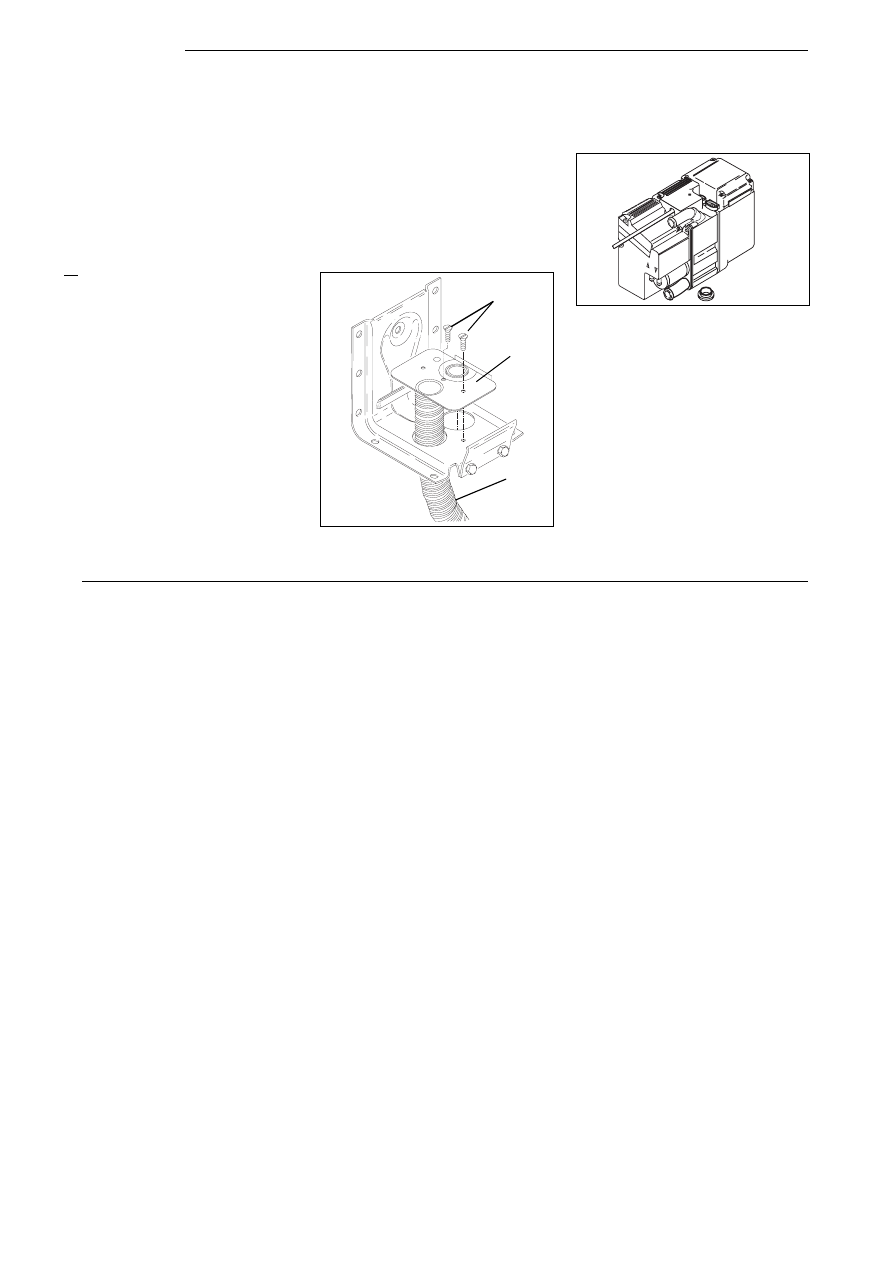
Insert Plate
The insert plate serves to connect exhaust gas and com-
bustion air lines.
The heater may be fastened to the mounting plate turned
by 180° provided the insert plate has also been turned ac-
cordingly.
The exhaust gas line is preassembled at the insert plate
whereas the combustion air line is to be attached by
means of a hose clamp during installation.
The insert plate is to be mounted to the bracket by means
of 2 M3 screws.
NOTE:
A coding is provided on the insert plate to ensure proper at-
tachment of exhaust gas and combustion air connections
of the heater relative to the insert plate.
Gasket at Exhaust Gas Outlet
Make sure that the gasket is fitted.
The gasket provided at the exhaust gas outlet of
the heater is to be replaced prior to each reinstal-
lation.
Exhaust Gas Pipe
The exhaust gas line (inside diameter 22 mm) is permitted
to have a length of up to 2 m and may feature several
bends (total of 270°, smallest bending radius 50 mm).
The exhaust gas line as a whole must not be shorter than
500 mm.
The exhaust muffler should preferably be installed near the
heater, but at least 200 mm away from the heater.
The exhaust silencer must not be mounted in the vicinity of
the combustion air intake opening.
M3 x 8 DIN695
Insert plate
Exhaust
gas pipe
CAUTION:
Do not use sheet-metal
screws for attaching in-
sert plate.
Fig. 9:
Insert plate
Mounting position
Fig. 10:
Exhaust Gas Seal
Thermo Top
6
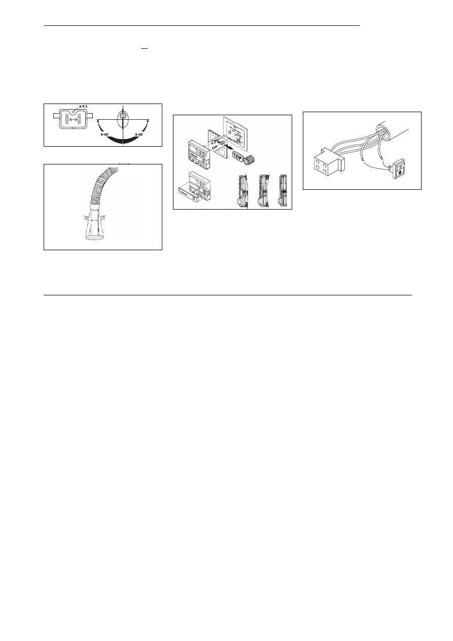
The discharge opening of the exhaust pipe must
not point
in the direction of travel (see Fig. 12).
Rigid pipes made of unalloyed steel with a minimum wall
thickness of 1.0 mm or flexible tubes of alloyed steel are to
be used as exhaust pipes only.
NOTE:
Any collection of condensation water in the exhaust pipe
must be drained immediately; if required, it is permitted to
drill a condensation water drain hole
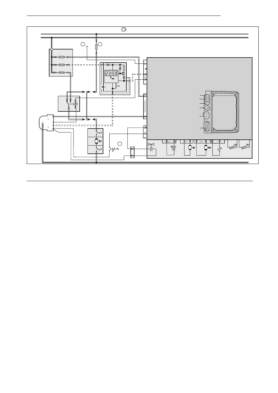
Electrical Connections
Control Unit/Heater Connection
The electrical connection of the heaters is to be performed
in accordance with Fig. 15.
Installation and Connection of Digital Timer
Installation of the digital timer is to be performed in accordance
with Fig. 13. A drilling template is part of the scope of delivery!
Connection of the digital timer is to be performed in accord-
ance with wiring diagram Fig. 15.
NOTE:
Do not press on the display panel during installation!
Vehicle Fan
The vehicle fan is activated via the vehicle fan relay fitted
to the fuse holder, see wiring diagram Fig. 15.
NOTE:
The connection terminal in the control unit (heater) is de-
signed for one fan relay (lmax = 0,5 A).
Connection of Summer/Winter Switch
NOTE:
It is not possible to connect a summer/winter switch when
a T70 is installed!
Connection of the summer/winter switch is to be performed
in accordance with Figs. 14 and 15.
NOTE:
The ends of the wires ’br’ and ’vi’ are inserted in the insula-
tion sleeving!
Installation of Telestart receiver T 70
The installation of the Telestart receiver and the aerial is to
be carried out in accordance with the T70 installation in-
structions.
’Teaching’ of Telestart transmitter
Following the installation of a Tele Thermo Top heater, the
transmitter must be allocated.
The Telestart transmitter must be "taught" in accordance
with the operating instructions.
Fig. 11:
Exhaust muffler
Direction of flow (not specified)
preferreed direction of discharge 90°
±
10°
Fig. 12:
Exhaust pipe discharge opening
Mounting position
Fig. 13:
Installation of Digital Timer
S5
br
plug
timer
vi
insulate
Fig. 14:
Connection of Summer/Winter Switch
Thermo Top
7
Pos. Designation
Remarks
A1
Heater
Thermo Top
A2
Electronic control unit
A3
Flat fuse holder
B1
Flame detector
B2
Temperature sensor
B3
Overheating thermostat
E
Glow plug
F1
Fuse 15 amp
blade-type acc. to SAE J 1284
F2
Fuse 1 amp
blade-type acc. to SAE J 1284
F3
Fuse 25 amp
blade-type acc. to SAE J 1284
H1
LED (in pos. P)
operation indicator
K3
Relay (in pos. A3)
vehicle fan
M1
Motor
combustion air fan
M2
Motor
circulating pump
M3
Motor
vehicle fan
P
Digital timer
for presetting operating times
S1
Switch for vehicle fan
S1 or S2 depending on vehicle
S2
Switch for vehicle fan
S1 or S2 depending on vehicle
S5
Switch
summer/winter switch
X9
Connector, 4-pole
X14
Connector, 6-pole
splash-water protected
X15
Connector, 2-pole
splash-water protected
X16
Connector, 2-pole
splash-water protected
X17
Connector, 2-pole
splash-water protected
X18
Connector, 2-pole
splash-water protected
X19
Connector, 2-pole
splash-water protected
X20
Connector, 2-pole
splash-water protected
X21
earth connection
Y2
Solenoid valve
Cable cross sections
< 7.5 m
7.5 - 15 m
0.5 mm
2
0.75 mm
2
0.75 mm
2
1.5 mm
2
1.5 mm
2
2.5 mm
2
2.5 mm
2
4.0 mm
2
4.0 mm
2
6.0 mm
2
Cable colours
bl
br
ge
gn
gr
or
rt
sw
vi
ws
blue
brown
yellow
green
grey
orange
red
black
violet
white
Legend for wiring diagrams:
➀
Diagnostic link
➁
Vehicle fan fuse installed in vehicle vorhanden
➂
Option
Thermo Top
8
M
M
M
-
+
(75) 15
30
rt
ge
OUT
sw
br
br
br
sw
Heiz
en
Lüften
bl
vi
+15
87a
86
85
87
30
31
I max. = 0,5 A
gn/ws
rt
rt
rt
br
br
4
3
2
1
2
1
6
5
2
1
2
1
1
1
2
2
ϑ
ϑ
ϑ
1
2
Y1
P
X9
X9
H1
B2
A1
X14
F1
F2
F3
K3
B3
M1
X17
X18
M2
X19
B1
A2
X14
X20
X21
X15
A3
1
3
2
S5
X16
E
M3
S2
S1
6
4
1
2
3
5
1
2
1
2
1
1
1
2
2
2
X14
X15
X16
X18
X19
A
B
C
X17
Fig. 15:
Automatic Control for
Thermo Top, Thermo Top T and Tele Thermo Top, 12V Digital Timer (Legend see page 8)
Thermo Top
9

Initial Operation
After the heater has been installed, the water circuit and
the fuel supply system are to be thoroughly bled. In so
doing the vehicle manufacturer’s instructions are to be ad-
hered to.
The fuel intermediate reservoir is to be filled by allowing
the engine to run for at least 2 minutes.
Perform a test run of the heater thereby checking all water
and fuel connections for leakage and secure attachment.
Should the heater fail during operation troubleshooting is
to be carried out.
Malfunctions
Shut-Down Due to Malfunctions of the Heater
If
no flame forms fuel is delivered for max. 170 seconds.
If
the flame goes out during operation fuel is delivered for
max. 85 seconds.
In the event of
overheating (tripping of safety thermostat),
fuel supply is immediately stopped.
In all cases (except of combustion air fan defects) an after-
run period of 120 seconds will follow if the system is shut
down on account of malfunctions.
CAUTION:
No indication occurs in the case of overheating.
Shut-Down Due to Undervoltage or Overvoltage
In the case of an undervoltage of 9,8
±
0.3 V (measured at
cable harness input) occurring over a period of 20 second-
s, the unit will be shut down and an after-run period of 120
seconds will follow.
In the case of an overvoltage of 15,5 + 0.5 V
(measured at the heater) occurring over a period of
more than 6 seconds, the unit will also be shut down
and an after-run period follows.
Interlock deactivation of the heater after a fault lock-
out situation
Fault lock-out deactivation is to be performed in accord-
ance with the operating instructions.
Thermo Top
10

Troubleshooting
Error Symptom
Possible cause
Remedy
Heater can’t be switched on
Heater is in the overheating lock-out mode
Remove 15A fuse
Determine cause
Summer/winter switch in summer position
Switch to correct position
Discharged battery
Charge
Defective fuse
Replace
Defective digital timer
Use testing device on heater and check if digital timer switches properly:
disconnect connector X14 from heater, connect testing device and switch
on digital timer. The indicator lamp must light up; if not, the timer is defective
and the power supply to the timer is disrupted.
Alternatively: Check if 12 V voltage is present across contact 1 (6-pole
connector).
Break in the power supply to the digital timer
Check if 12V voltage is present across the red and brown wires of the
connector of the digital timer. If necessary check fuse F2 and cables wires.
Break in the power supply to the heater
Disconnect connector X 15 from the heater and use the testing device to
check for presence of voltage.
Heater fails to ignite, fan motor is operating
Intermediate fuel reservoir empty
Allow vehicle engine to run for approx. 30 seconds
Heater operates for a few minutes only
Heater not seated properly in its support, exhaust gas is
aspirated
Loosen 2 M6 screws and position correctly
Fuel lines of heater not properly connected. Flow and return
pipes were interchanged.
Connect fuel lines in accordance with installation instructions
A non-return valve may have been installed in the fuel line
between heater and vehicle tank, or in the vehicle tank itself
(intermediate fuel reservoir is not ventilated).
Kinked coolant hose or system has not been bled completely
Check line routing, bleed cooling system (start engine)
Insufficient heat output
Heater control lever or vehicle fan out incorrectly set
Prior to operating the heater set heater control lever to "warm" and set fan
switch to a higher setting.
Vehicle fan fails to switch on when the thre-
shold temperature (>30° of coolant) is
reached
Defective fuse F3
Replace fuse
Blue smoke or soot in the exhaust gas,
heater is emitting smoke
Kinked or blocked suction or exhaust gas line
Check lines for unobstructed passage
Installation fault, heater is not properly seated in its support, or
gasket of exhaust gas pipe was not installed
Check installation
Thermo Top
11

Versions
Thermo Top
Petrol
type BW 50
Water heater for fuel “petrol” with
intermediate fuel reservoir.
Thermo Top
Diesel
type DW 50
Water heater for fuel “Diesel/fuel
oil EL” with intermediate fuel reser-
voir
The water heaters
Thermo Top
are designed to operate on 12
volts.
Thermo Top
12
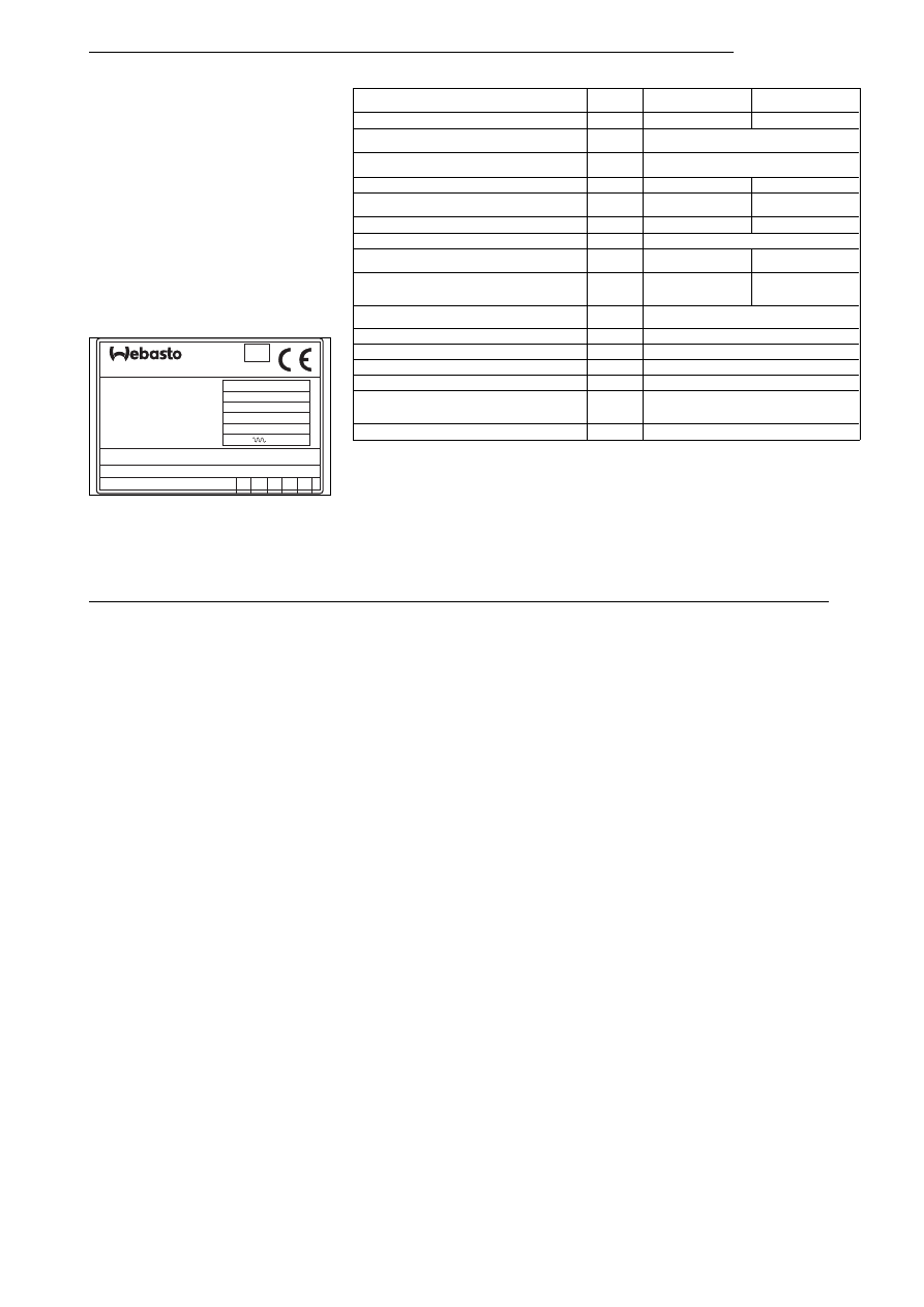
Technical Data
Unless limit values are indicated, the technical data shown
in the Table on the right apply with the usual
±
10% toler-
ances for heaters at an ambient temperature of +20°C and
at rated voltage.
Fuel for
Thermo Top
(Petrol) type BW 50:
The type of fuel prescribed by the manufacturer of the ve-
hicle may be used.
Fuel for
Thermo Top
(Diesel/fuel oil EL) type DW 50:
The Diesel fuel recommended for use by the vehicle manu-
facturer is suitable as fuel for the heater.
Any negative effect caused by additives is not known.
Heater
Operation
Petrol
type BW 50
Diesel
type DW 50
Mark of confirmity
~S238
~S239
Type
Water heater with
vaporizing-type burner
Heat output
full load
part load
5,0 kW
2,5 kW
Fuel
Petrol
Diesel/EL fuel oil
Fuel consumption
full load
part load
0,67 l/h
0,33 l/h
0,59 l/h
0,29 l/h
Rated voltage
12 Volt
12 Volt
Operating voltage range
10 ... 14 Volt
Rated power consumption with circulation pump
(without vehicle fan)
full load
part load
44 W
27 W
44 W
27 W
Max. ambient temperature:
Heater:
-
operation
-
storage
-40°... + 60°C
-40°... +120°C
-40°... + 80°C
-40°... +120°C
Max. allow. working pressure
(heat transfer medium)
0,4 ... 2,0 bar
Heat exchanger capacity
0,15 l
Min. cooling system capacity
4,00 l
Flow rate of circulating pump at roughly 0,1 bar
500 l/h
CO
2
content in exhaust gas (perm. operating range)
9,5 ... 12,0 Vol .-%
Dimensions of heater
Length 240 mm
Width 103 mm
Height 168 mm
Weight
4.3 kg
HEIZGERÄT Typ
Wärmestrom
Spannung/El.Leistung
Brennstoff
zul. Betriebsüberdruck
Ident Nr. 908868
Inbetriebnahmejahr
Prüfzeichen
2 bar
S 236
Benzin
5 KW
12V/44W
BW 50
01
20
00
20
99
19
Ausf. 34 Fabr.Nr.
Thermosysteme GmbH
MADE IN
GERMANY
021279
e1
Fig. 16:
Type plate
Thermo Top
13
A
CND
J
ZA
AUS
NZ
FIN
NL
B
RA
GB
P
RCH
GR
PL
H
RF
USA
I
SLO
IS
SW
SK
L
TR
UA
N
Service Phone Line
In case you encounter technical problems with your auxiliary heater -
Simply dial the
for your country as indicated below.
Webasto's Top Service for our customers
Webasto's world-wide Service Network will be glad to assist you!
Service Phone Number
Europe
America
Asia
Africa
Australia
Austria
Vienna
01-6043780
Belgium
Brussels
02-558 06 60
Switzerland
Allschwil
061-486 95 80
Czech Republic
Praha
02-464 468
Germany
Stockdorf
01805-932278
Denmark
Copenhagen
036-78 66 66
Spain
Sant Just Desvern
03-473 15 00
France
Maisons Alfort
01-45 18 35 35
Bulgarien
Sofia
02-9559536
Canada
Ontario
0905-335 41 34
Argentinia
Buenos Aires
01-746 96 00
Chile
Santiago de Chile
02-234 43 11
United States
48446 MI
0810-245 24 00
Japan
Tokyo
03-343 221 76
South Africa
Wetton
021-761 99 71
Australia
South Melbourne
03-699 83 22
New Zealand
Wellington
04-568 42 89
Finnland
Helsinki
0-968271
Great Britain
Doncaster Carr
01302-322232
Greece
Athen
01-252 09 96
Hungaria
Budapest
01-350 23 38
Italy
Milano
02-413 01 01
Iceland
Gardabae
354-567 2330
Luxembourg
Brussels
02-558 06 60
Norway
Oslo
022-709 000
Netherlands
Almere-Buiten
036-535 91 11
Portugal
Lisbon
01-363 99 50
Polen
Lomianki
4822-751 77 87
Russia
Moscow
095-917 18 10
Slovenia
Ljubljana
061-553 161
KoŠice
01-957 477 92
Sweden
Stockholm
08-923 00
Turkey
Istanbul
0212-623 21 35
Ukraine
Lwiw
0322-911 564
BG
CH
CR
D
DK
E
F
Slowakei
Document Outline
- Operating Instructions
- Table of contents
- Legal Provisions
- Use of the Water Heater
- Installation Location
- Nameplate
- Connection to the Vehicle Cooling System
- Installation example
- Fuel Installation
- Combustion Air Supply
- Support Plate
- Insert Plate
- Gasket at Exhaust Gas Outlet
- Exhaust Gas Pipe
- Electrical Connections
- Initial Operation
- Malfunctions
- Shut-Down Due to Undervoltage or Overvoltage
- Interlock deactivation of the heater after a fault lockout situation
- Troubleshooting
- Versions
- Technical Data
- Service Phone Line
Wyszukiwarka
Podobne podstrony:
Webasto - Thermo Top Z-C - opis, Webasto
MAN Ogrzewanie Webasto Thermo 230,300,350 obsługa i montaż(1)
MAN Ogrzewanie Webasto Thermo 230,300,350 obsługa i montaż(1)
Thermo Top ZC
Schemat Thermo Top V
MAN Ogrzewanie Webasto Thermo 230,300,350 obsługa i montaż(1)
Thermo Top Z C opis i schematy [EN]
Instrukcja Obsługi AIR TOP WEBASTO
01 Top 20 ports
01 Thermoregulation, Fever PLid Nieznany (2)
HD44780 ATTINY13 BOARD TOP MIRROR
Opisy top osnowa AGH syt i wykaz wys
Linear Technology Top Markings Nieznany
blokada samochodu, Top Silkscreen Overlay
pcb pdf, Top Paste Mask Print
egz top pyt 130206 odp
Instrukcja montażu Air Top 3500 ST
więcej podobnych podstron