
2
<ARB7192>
IMPORTANT
The lightning flash with arrowhead symbol, within
an equilateral triangle, is intended to alert the
user to the presence of uninsulated "dangerous
voltage" within the product's enclosure that may
be of sufficient magnitude to constitute a risk of
electric shock to persons.
The exclamation point within an equilateral
triangle is intended to alert the user to the presence
of important operating and maintenance
(servicing) instructions in the literature
accompanying the appliance.
CAUTION:
TO PREVENT THE RISK OF ELECTRIC SHOCK, DO
NOT REMOVE COVER (OR BACK). NO USER-SER-
VICEABLE PARTS INSIDE. REFER SERVICING TO
QUALIFIED SERVICE PERSONNEL.
RISK OF ELECTRIC SHOCK
DO NOT OPEN
CAUTION
This equipment has been tested and found to comply with the limits for a Class B digital device, pursuant to Part 15 of the FCC Rules.
These limits are designed to provide reasonable protection against harmful interference in a residential installation. This equipment
generates, uses, and can radiate radio frequency energy and, if not installed and used in accordance with the instructions, may cause
harmful interference to radio communications. However, there is no guarantee that interference will not occur in a particular
installation. If this equipment does cause harmful interference to radio or television reception, which can be determined by turning
the equipment off and on, the user is encouraged to try to correct the interference by one or more of the following measures:
– Reorient or relocate the receiving antenna.
– Increase the separation between the equipment and receiver.
– Connect the equipment into an outlet on a circuit different from that to which the receiver is connected.
– Consult the dealer or an experienced radio/TV technician for help.
Thank you for buying this Pioneer product.
Please read through these operating instructions so you will know
how to operate your model properly. After you have finished
reading the instructions, put them away in a safe place for future
reference.
In some countries or regions, the shape of the power plug and
power outlet may sometimes differ from that shown in the
explanatory drawings. However the method of connecting and
operating the unit is the same.
THE POWER SWITCH IS SECONDARY CONNECTED AND
THEREFORE DOES NOT SEPARATE THE UNIT FROM MAINS
POWER IN THE STANDBY POSITION.
IMPORTANT NOTICE
The serial number for this equipment is located on the rear panel.
Please write this serial number on your enclosed warranty card
and keep it in a secure area. This is for your security.
WARNING:
TO PREVENT FIRE OR SHOCK HAZARD, DO NOT
EXPOSE THIS APPLIANCE TO RAIN OR MOISTURE.
SET UP
OPERA
TION
3
<ARB7192>
READ INSTRUCTIONS — All the safety and operating
instructions should be read before the product is
operated.
RETAIN INSTRUCTIONS — The safety and operating
instructions should be retained for future reference.
HEED WARNINGS — All warnings on the product and
in the operating instructions should be adhered to.
FOLLOW INSTRUCTIONS — All operating and use
instructions should be followed.
CLEANING — Unplug this product from the wall outlet
before cleaning. The product should be cleaned only
with a polishing cloth or a soft dry cloth. Never clean
with furniture wax, benzine, insecticides or other
volatile liquids since they may corrode the cabinet.
ATTACHMENTS — Do not use attachments not
recommended by the product manufacturer as they
may cause hazards.
WATER AND MOISTURE — Do not use this product
near water — for example, near a bathtub, wash
bowl, kitchen sink, or laundry tub; in a wet basement;
or near a swimming pool; and the like.
ACCESSORIES — Do not place this product on an
unstable cart, stand, tripod, bracket, or table. The
product may fall, causing serious injury to a child or
adult, and serious damage to the product. Use only
with a cart, stand, tripod, bracket, or table
recommended by the manufacturer, or sold with
the product. Any mounting of the product should
follow the manufacturer’s instructions, and should
use a mounting accessory recommended by the
manufacturer.
CART — A product and cart combination should be
moved with care. Quick stops, excessive force, and
uneven surfaces may cause the product and cart
combination to overturn.
GROUNDING OR POLARIZATION
¶ If this product is equipped with a polarized alternating
current line plug (a plug having one blade wider than
the other), it will fit into the outlet only one way. This
is a safety feature. If you are unable to insert the plug
fully into the outlet, try reversing the plug. If the plug
should still fail to fit, contact your electrician to
replace your obsolete outlet. Do not defeat the
safety purpose of the polarized plug.
¶ If this product is equipped with a three-wire
grounding type plug, a plug having a third (grounding)
pin, it will only fit into a grounding type power outlet.
This is a safety feature. If you are unable to insert the
plug into the outlet, contact your electrician to
replace your obsolete outlet. Do not defeat the
safety purpose of the grounding type plug.
POWER-CORD PROTECTION — Power-supply cords
should be routed so that they are not likely to be
walked on or pinched by items placed upon or
against them, paying particular attention to cords at
plugs, convenience receptacles, and the point where
they exit from the product.
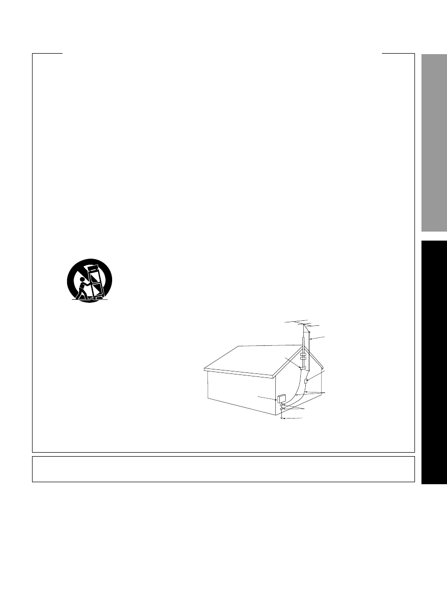
OUTDOOR ANTENNA GROUNDING — If an outside
antenna or cable system is connected to the product,
be sure the antenna or cable system is grounded so
as to provide some protection against voltage surges
and built-up static charges. Article 810 of the National
Electrical Code, ANSI/NFPA 70, provides information
with regard to proper grounding of the mast and
supporting structure, grounding of the lead-in wire
to an antenna discharge unit, size of grounding
conductors, location of antenna-discharge unit,
connection to grounding electrodes, and
requirements for the grounding electrode. See Figure
A.
LIGHTNING — For added protection for this product
during a lightning storm, or when it is left unattended
and unused for long periods of time, unplug it from
the wall outlet and disconnect the antenna or cable
system. This will prevent damage to the product
due to lightning and power-line surges.
POWER LINES — An outside antenna system should
not be located in the vicinity of overhead power lines
or other electric light or power circuits, or where it
can fall into such power lines or circuits. When
installing an outside antenna system, extreme care
should be taken to keep from touching such power
lines or circuits as contact with them might be fatal.
OVERLOADING — Do not overload wall outlets,
extension cords, or integral convenience receptacles
as this can result in a risk of fire or electric shock.
OBJECT AND LIQUID ENTRY — Never push objects of
any kind into this product through openings as they
may touch dangerous voltage points or short-out
parts that could result in a fire or electric shock.
Never spill liquid of any kind on the product.
SERVICING — Do not attempt to service this product
yourself as opening or removing covers may expose
you to dangerous voltage or other hazards. Refer all
servicing to qualified service personnel.
DAMAGE REQUIRING SERVICE — Unplug this product
from the wall outlet and refer servicing to qualified
service personnel under the following conditions:
¶ When the power-supply cord or plug is damaged.
¶ If liquid has been spilled, or objects have fallen into
the product.
¶ If the product has been exposed to rain or water.
¶ If the product does not operate normally by following
the operating instructions. Adjust only those controls
that are covered by the operating instructions as an
improper adjustment of other controls may result in
damage and will often require extensive work by a
qualified technician to restore the product to its
normal operation.
¶ If the product has been dropped or damaged in any
way.
¶ When the product exhibits a distinct change in
performance — this indicates a need for service.
REPLACEMENT PARTS — When replacement parts
are required, be sure the service technician has used
replacement parts specified by the manufacturer or
have the same characteristics as the original part.
Unauthorized substitutions may result in fire, electric
shock, or other hazards.
SAFETY CHECK — Upon completion of any service or
repairs to this product, ask the service technician to
perform safety checks to determine that the product
is in proper operating condition.
WALL OR CEILING MOUNTING — The product should
not be mounted to a wall or ceiling.
HEAT — The product should be situated away from heat
sources such as radiators, heat registers, stoves, or
other products (including amplifiers) that produce
heat.
IMPOR TANT SAFETY INSTRUCTIONS
GROUND
CLAMP
ANTENNA
DISCHARGE UNIT
(NEC SECTION 810-20)
GROUNDING CONDUCTORS
(NEC SECTION 810-21)
GROUND CLAMPS
POWER SERVICE GROUNDING
ELECTRODE SYSTEM
(NEC ART 250, PART H)
ELECTRIC
SERVICE
EQUIPMENT
Fig. A
ANTENNA
LEAD IN
WIRE
NEC — NATIONAL ELECTRICAL CODE
VENTILATION — Slots and openings in the cabinet are
provided for ventilation and to ensure reliable
operation of the product and to protect it from
overheating, and these openings must not be
blocked or covered. The openings should never be
blocked by placing the product on a bed, sofa, rug,
or other similar surface. This product should not be
placed in a built-in installation such as a bookcase or
rack unless proper ventilation is provided or the
manufacturer’s instructions have been adhered to.
POWER SOURCES — This product should be operated
only from the type of power source indicated on the
marking label. If you are not sure of the type of
power supply to your home, consult your product
dealer or local power company.
LOCATION – The appliance should be installed in a
stable location.
NONUSE PERIODS – The power cord of the appliance
should be unplugged from the outlet when left
unused for a long period of time.
Information to User
Alteration or modifications carried out without appropriate authorization may invalidate the user's right to operate the equipment.

4
<ARB7192>
Features
Dolby Digital and Dolby Pro Logic
No need to worry about program formats! When playing Dolby Digital or Dolby Surround software in the
(Dolby)
Surround mode, decoding switches automatically according to the input signal. All you have to do is sit back and
enjoy! (When connecting a DVD/LD player or LD player using the AC-3 RF output, a commercially available RF
demodulator (RFD-1) is required.)
Manufactured under license from Dolby Laboratories. “Dolby”, “AC-3”, “Pro Logic”, “ and double-D
symbol are trademarks of Dolby Laboratories. Confidential Unpublished Works. © 1992 - 1997 Dolby
Laboratories, Inc. All rights reserved.
Various Surround Effects (DSP)
The DSP (Digital Signal Processing) surround mode allows you to transform your living room into six different
sonic environments when listening to music or watching movies.
Midnight Listening Mode
When late night hours or other factors require that the volume be kept low, the surround effects may tend to
become less than satisfactory. When the midnight listening mode is on, you can enjoy the effects of quality
surround sound even at low volumes.
5.1 Channel Input
By connecting components equipped with 5.1 channel output to the DVD 5.1 channel input on this unit, you can
enjoy 5.1 channel surround sound. Connections can be made to a DVD player, Multi channel decoder equipped
with 5.1 channel analog output jacks.
5 Channels of Independent Amplification
This receiver incorporates 5 independent 80 watt power amplifiers which enable high quality playback of Dolby
Digital surround sound. This construction provides improved linearity and accurate reproduction of each channel
for true high fidelity reproduction from even the most demanding Dolby Digital program sources.
Energy-saving Design
This unit is designed to use minimal electricity when power is switched OFF (during Standby). Regarding the value
of the power consumption in standby mode, refer to “Specifications” on page 46.

SET UP
OPERA
TION
5
<ARB7192>
Table of Contents
Introductory Information ............................................................ 6
Checking the Supplied Accessories .......................................................... 6
How to Use This Manual ........................................................................... 6
Power Connection (AC OUTLET) .............................................................. 6
Preparing the Remote Control .................................................................. 6
When Making Cable Connections ............................................................. 7
Connections ................................................................................. 8
Audio Components Connections .............................................................. 9
Video Components Connections ............................................................ 10
DVD 5.1 Channel Connection .................................................................. 12
Preparations .............................................................................. 15
Setting Up for Surround Sound .............................................................. 15
Names of Parts and Basic Operations ..................................... 21
Sound Modes ............................................................................ 25
Switching ANALOG/DIGITAL Signal Input ............................................. 26
Playing Sources with Dolby Digital Sound ............................................ 28
Selecting a Sound Mode ......................................................................... 29
DVD 5.1ch input playback ........................................................................ 30
Listening in MIDNIGHT Listening Mode ................................................ 30
Ajusting Bass and Treble Frequencies (Tone Control) .......................... 31
Tuner Operations ....................................................................... 32
Automatic and Manual Tuning ................................................................ 32
Memorizing Frequently Tuned Stations ................................................. 34
Recalling the Memorized Stations .......................................................... 35
Other Operations ...................................................................... 36
Recording from Audio Components ...................................................... 36
Recording from Video Components ....................................................... 37
Remote Controlling Other PIONEER Components ................................ 38
Additional Information ............................................................. 43
6
<ARB7192>
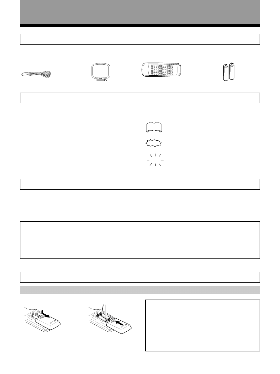
Loading the batteries
Introductory Information
“AA” IEC R6P batteries x 2
FM wire antenna
AM loop antenna
Remote control unit
Checking the Supplied Accessories
Please check that you have received all of the following accessories with the receiver.
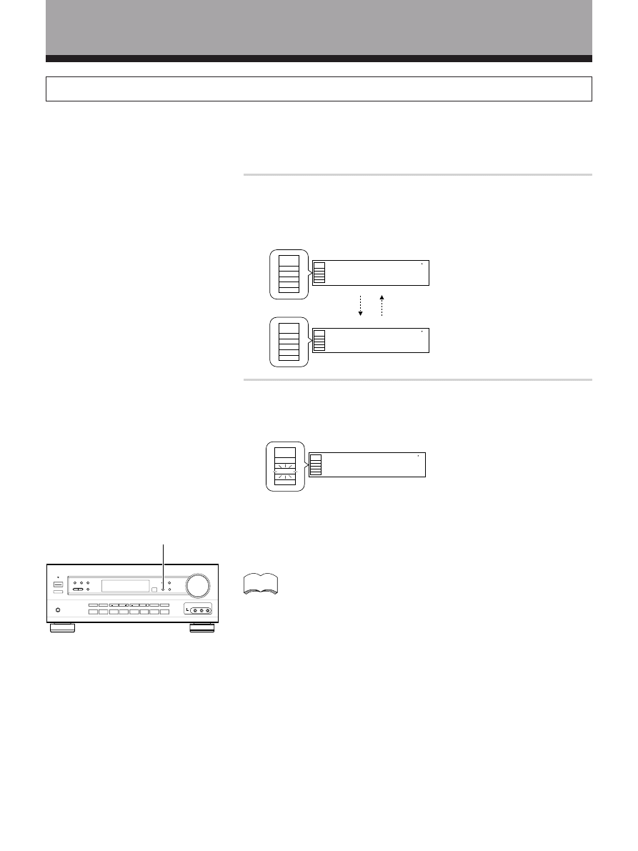
The following marks and symbols are used throughout
this manual:
Provides additional information, precautions,
and advice.
Indicates a blinking button, indicator, or
display.
Indicates a steadily lit button, indicator, or
display.
How to Use This Manual
When you notice a decrease in the operating range of
the remote control, replace all batteries with new ones.
AA dry cell batteries ((“AA” IEC R6P)
×2)
\
CAUTION!
Incorrect use of batteries may result in such hazards
as leakage and bursting. Observe the following
precautions.
• Never use new and old batteries together.
• Insert the plus and minus sides of the batteries
properly according to the marks in the battery case.
• Batteries with the same shape may have different
voltages. Do not use different batteries together.
Preparing the Remote Control
This manual is divided into two main sections :
SET UP
This section explains how to make the necessary
connections from the receiver to your other audio and
video components. Receiver operations described later
in this section under the heading “Preparations” enable
you to set up and customize your home entertainment
center.
OPERATION
This section provides complete information about
operation of the receiver and supplied remote control.
memo
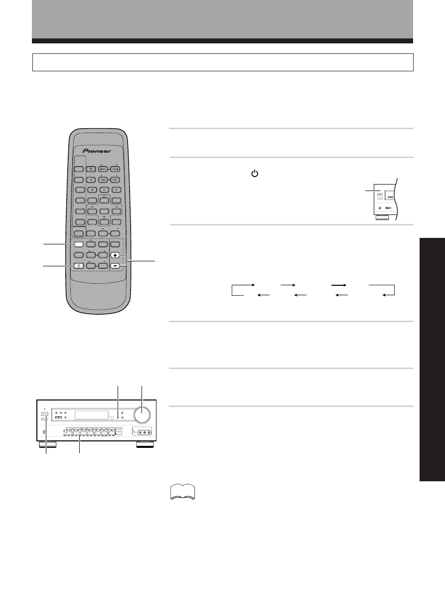
Power connection (AC OUTLET)
[SWITCHED 100 W (0.8 A) MAX]
Switching this receiver on or putting it in standby also switches components connected to the receiver’s AC OUTLET
jacks on and off. When connecting components to the AC OUTLET jacks, leave the power switch of the connected
components in the ON position. Total power consumption of connected components should not exceed 100W (0.8 A).
CAUTION!
• To avoid malfunction, overheating, and possible fire risk, do not connect high-wattage appliances such as blow
dryers and irons to the AC OUTLET jacks.
• Do not connect a monitor or TV set.
Even if the power consumption of the TV or monitor is within the acceptable limits, when monitors or TV sets are
switched on, they consume a large amount of power and may exceed the capacity of this receiver.
SET UP
7
<ARB7192>
Introductory Information
Operating other PIONEER components
Receiver Installation
• Do not place objects directly on top of this unit. It will prevent proper heat dispersal.
• When installing in a rack, etc., be sure to leave more than 8 inches of space above the receiver.
You can also control PIONEER components
(and those made by other manufacturers) by
pointing the receiver’s remote control directly
at the respective component. This type of
operation does not require control cords.
memo
It is recommended that you place the
receiver to the left of your cassette and/
or video decks. This will prevent noise
caused by leakage flux from the
transformer in the receiver. If you
experience noise during playback of
your cassette and/or video decks, move
them farther away from the receiver.
Receiver
Leave more than 8 inches (20 cm)
When Making Cable Connections
Be careful not to arrange cables in a manner that bends
the cables over the top of this unit as shown in the
illustration. If the cables are brought over this unit, the
magnetic field produced by the transformers in this unit
may cause a humming noise to come from the speakers.
Remote Control
Receiver
To CONTROL IN
terminal of another
PIONEER component
bearing the
Î mark.
PIONEER component
bearing the
Î mark.
Connecting an optional control cord allows you to
operate other PIONEER components simply by pointing
the receiver’s remote control at the remote sensor on the
front panel of the receiver. The receiver then sends the
remote control signals to the other devices via the
CONTROL OUT terminal.
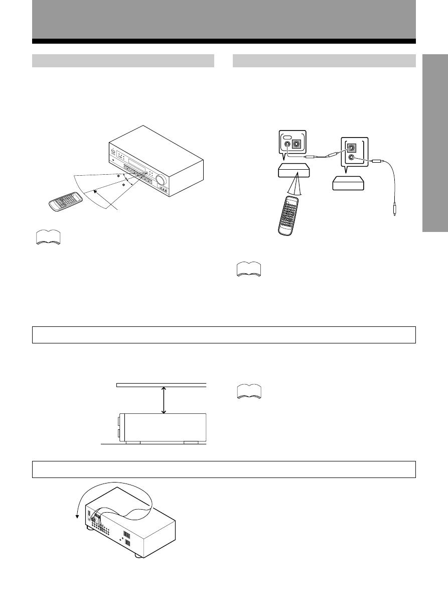
Operating range of remote control unit
Remote control may not function properly if :
• There are obstacles between the remote
control and the remote sensor.
• Direct sunlight or fluorescent light is shining
onto the remote sensor.
• The receiver is located near a device
emitting infrared rays.
• Operated simultaneously with another
remote control which uses infrared rays.
Point the remote control toward the remote sensor
Î on
the front panel of this unit to operate. The remote control
unit will operate the receiver for up to a distance of 23
feet (7 m) within 30° angle on each side of the sensor of
the remote sensor as illustrated below.
memo
memo
30
30
23 feet(7m)
OUT
IN
CONTROL
OUT
IN
CONTROL
8
<ARB7192>
Connections
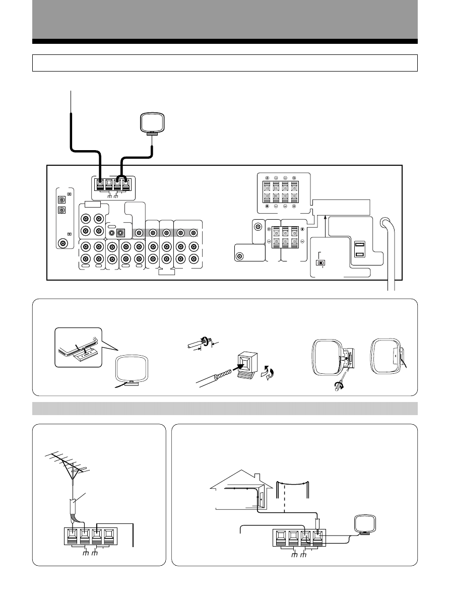
Antennas
Using external antennas
7 To improve FM reception
Connect an external FM antenna.
7 To improve AM reception
Connect a 15 to 18 feet (5~6 m) length of vinyl-coated wire to the AM
antenna terminal in addition to the supplied AM loop antenna.
For the best possible reception, suspend horizontally outdoors.
75
Ω coaxial cable
Outdoor antenna
15~18 feet (5~6 m)
7 AM loop antenna
3/8 in.(10mm)
1 Assemble the antenna.
2 Twist exposed wire strands
together and insert into AM
antenna terminals.
3 Attach to a wall, etc. (if desired)
and face toward the direction
providing the best reception.
Indoor antenna
(Vinyl-coated wire)
Connect the FM wire antenna and fully extend (for best reception, attach horizontally along
a window frame, etc.).
AM loop antenna
FM wire antenna
(See below)
H
GND
FM
UNBAL
75
Ω
LOOP
ANTENNA
AM
H
GND
FM
UNBAL
75
Ω
LOOP
ANTENNA
AM
VIDEO
OUT
FM
UNBAL
75
Ω
OUT
IN
CONTROL
LOOP
ANTENNA
AM
ANTENNA
OPT
1
OPT
2
COAX
PLAY
REC
MD/TAPE 1
N
IN
OUT
PLAY
REC
N
IN
IN
N
IN
N
OUT
IN
OUT
OUT
CD
TAPE 2 MONITOR
TO
MONITOR
TV
R
L
TV/
SAT
DVD/
LD
DVD 5 1 CH
INPUT
SURROUND
L
R
CENTER
SUBWOOFER
DVD 5 1 CH
FRONT
VCR
PCM/
PCM/
CENTER
PREOUT
SUB
WOOFER
PREOUT
L
L
R
R
B
A
SURROUND
SPEAKERS
CENTER
SPEAKER
CAUTION:
CAUTION:
SEE NSTRUCTION
MANUAL
8 16
Ω / SPEAKER
8 16
Ω / HAUT
PARLEUR
6 LESS THAN 8
Ω /SPEAKER
6 MO NS DE 8
Ω /HAUT PARLEUR
IMPEDANCE SELECTOR
L
R
VIDEO
DIGITAL
IN
L
R
B
A
FRONT SPEAKERS
L
R
SPEAKER IMPEDANCE
6
Ω OR 8Ω 16Ω / SPEAKER
ATTENTION:
IMPEDANCE DE HAUT PARLEURS
6
Ω OU 8Ω 16Ω / HAUT PARLEUR
ATTENTION:
SE REPOTER AU
MODE D EMPLON
9
<ARB7192>
SET UP
VIDEO
OUT
FM
UNBAL
75
Ω
OUT
IN
CONTROL
LOOP
ANTENNA
AM
ANTENNA
OPT
1
OPT
2
COAX
PLAY
REC
MD/T PE 1
IN
IN
OUT
PLAY
REC
IN
IN
IN
IN
IN
IN
OUT
IN
OUT
OUT
CD
TAPE 2
ONITOR
TO
MONITOR
TV
R
L
TV/
SAT
DVD/
LD
DVD 5 1 CH
INPUT
SURROUND
L
R
CENTER
SUBWOOFER
DVD 5 1 CH
FRONT
VCR
PCM/
PCM/
CENTER
PREOUT
SUB
WOOFER
PREOUT
L
L
R
R
B
A
SURROUND
SPEAKERS
CENTER
SPEAKER
CAUTION:
CAUTION:
SEE INSTRUCT ON
MANUAL
8 16
Ω / SPEAKER
8 16
Ω / HAUT
PARLEUR
6 LESS THAN 8
Ω /SPEAKER
6 MOINS DE 8
Ω /HAUT PARLEUR
IMPEDANCE SELECTOR
L
R
VIDEO
DIGITAL
IN
L
R
B
A
FRONT SPEAKERS
L
R
SPEAKER IMPEDANCE
6
Ω OR 8Ω 16Ω / SPEAKER
ATTENTION:
IMPEDANCE DE HAUT PARLEURS
6
Ω OU 8Ω 16Ω / HAUT PARLEUR
ATTENTION:
SE REPOTER AU
MODE D EMPLON
REC
PLAY
L
R
L
R
REC
PLAY
L
R
L
R
L
OUTPUT
R
»
«
«
»
»
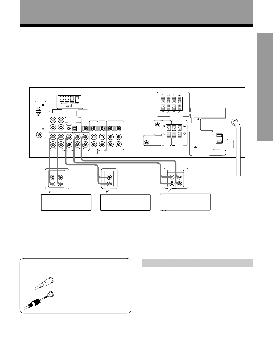
Audio Components Connections
Connections
Be sure to switch power to standby and remove the power cord from the wall outlet when you make or change
connections.
Connect your audio components as shown below. Refer to “Digital Connections” on page 11 when making digital
connections from your DVD or LD player.
7 Audio cords
Use audio cords (not supplied) to connect the audio
components.
Connect red plugs to R (right)
and white plugs to L (left).
Be sure to insert completely.
L
R
MD recorder
or Cassette deck
CD player
Cassette deck
*The arrows indicate the direction of the audio signal.
Cassette deck placement
Depending on where the cassette deck is placed, noise
may occur during playback of your cassette deck which
is caused by leakage flux from the transformer in the
receiver. If you experience noise, move the cassette deck
farther away from the receiver.
10
<ARB7192>
VIDEO
INPUT
VIDEO
L AUDIO R
VID
VI EO
O T
FM
UNBAL
75
Ω
OUT
IN
CONTROL
LOOP
ANTENNA
AM
ANTENNA
OPT
1
OPT
2
COAX
PLAY
REC
MD/TAPE 1
IN
IN
OUT
PLAY
REC
IN
IN
IN
IN
IN
IN
OUT
IN
OUT
OUT
CD
TAPE 2 MONITOR
TO
MON T R
TV
R
L
TV/
SAT
DVD/
LD
DVD 5 1 CH
INPUT
SURROUND
L
R
CENTER
SUBWOOFER
VD 5 1 CH
FRONT
VCR
PCM/
PCM/
CENTER
PREOUT
SUB
WOOFER
PREOUT
L
L
R
R
B
A
SURROUND
SPEAKERS
CENTER
SPEAKER
CAUTION:
CAUTION:
SEE INSTRUCTION
MANUAL
8 16
Ω / SPEAKER
8 16
Ω / HAUT
PARLEUR
6 LESS THAN 8
Ω /SPEAKER
6 MOINS DE 8
Ω /HAUT PARLEUR
IMPEDANCE SELECTOR
L
R
VIDEO
DIGITAL
IN
L
R
B
A
FRONT SPEAKERS
L
R
SPEAKER IMPEDANCE
6
Ω OR 8Ω 16Ω / SPEAKER
ATTENTION:
MPEDANCE DE HAUT PARLEURS
6
Ω OU 8Ω 16Ω / HAUT PARLEUR
ATTENTION:
SE REPOTER AU
MODE D EMPLON
V
OUTPUT
L
R
V
OUTPUT
L
R
V
INPUT
OUTPUT
V
L
R
L
R
INPUT
VI EO
»
»
»
»
«
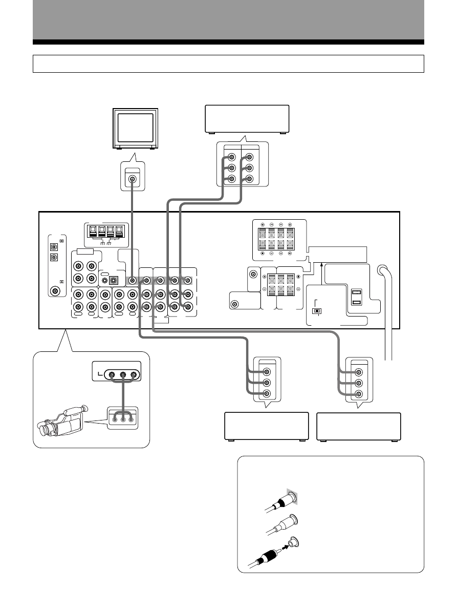
Connections
Video Components Connections
7 Audio/Video cords
Use audio/video cords (not supplied) to connect the
video components and a video cord to connect the TV
or monitor.
Connect red plugs to R (right),
white plugs to L (left), and the
yellow plugs to VIDEO.
Be sure to insert completely.
Video camera
(etc.)
7 Front
• Connect your video components as shown below. Also, refer to “Digital Connections” on page 11 when making
digital connections from your DVD or LD player.
TV
monitor
Video deck
DVD player
(or LD player)
TV tuner
(or satellite tuner)
L
R
VIDEO
11
<ARB7192>
SET UP
VIDEO
OUT
FM
UNBAL
75
Ω
OUT
IN
CONTROL
LOOP
ANTENNA
AM
ANTENNA
OPT
1
OPT
COAX
PLAY
REC
MD/TAPE 1
IN
N
OUT
PLAY
REC
IN
IN
IN
IN
IN
IN
OUT
IN
OUT
OUT
CD
TAPE 2 MONITOR
TO
MONITOR
TV
R
L
TV/
SAT
DVD/
LD
DVD 5 1 CH
INPUT
SURROUND
L
R
CENTER
SUBWOOFER
DVD 5 1 CH
FRONT
VCR
PCM/
PCM/
CENTER
PREOUT
SUB
WOOFER
PREOUT
L
L
R
R
B
A
SURROUND
SPEAKERS
CENTER
SPEAKER
CAUTION:
CAUTION:
SEE NSTRUCTION
MANUAL
8 16
Ω / SPEAKER
8 16
Ω / HAUT
PARLEUR
6 LESS THAN 8
Ω /SPEAKER
6 MOINS DE 8
Ω /HAUT PARLEUR
MPEDANCE SELECTOR
L
R
VIDEO
D GITAL
N
L
R
B
A
FRONT SPEAKER
L
R
SPEAKER IMPEDANCE
6
Ω OR 8Ω 16Ω / SPEAKER
ATTENTION:
IMPEDANCE DE HAUT PARLEURS
6
Ω OU 8Ω 16Ω / HAUT PARLEUR
ATTENTION:
SE REPOTER AU
MODE D EMPLON
OUT
COAX
OUT
DIGITAL
OUT
DIGITAL
»
»
»
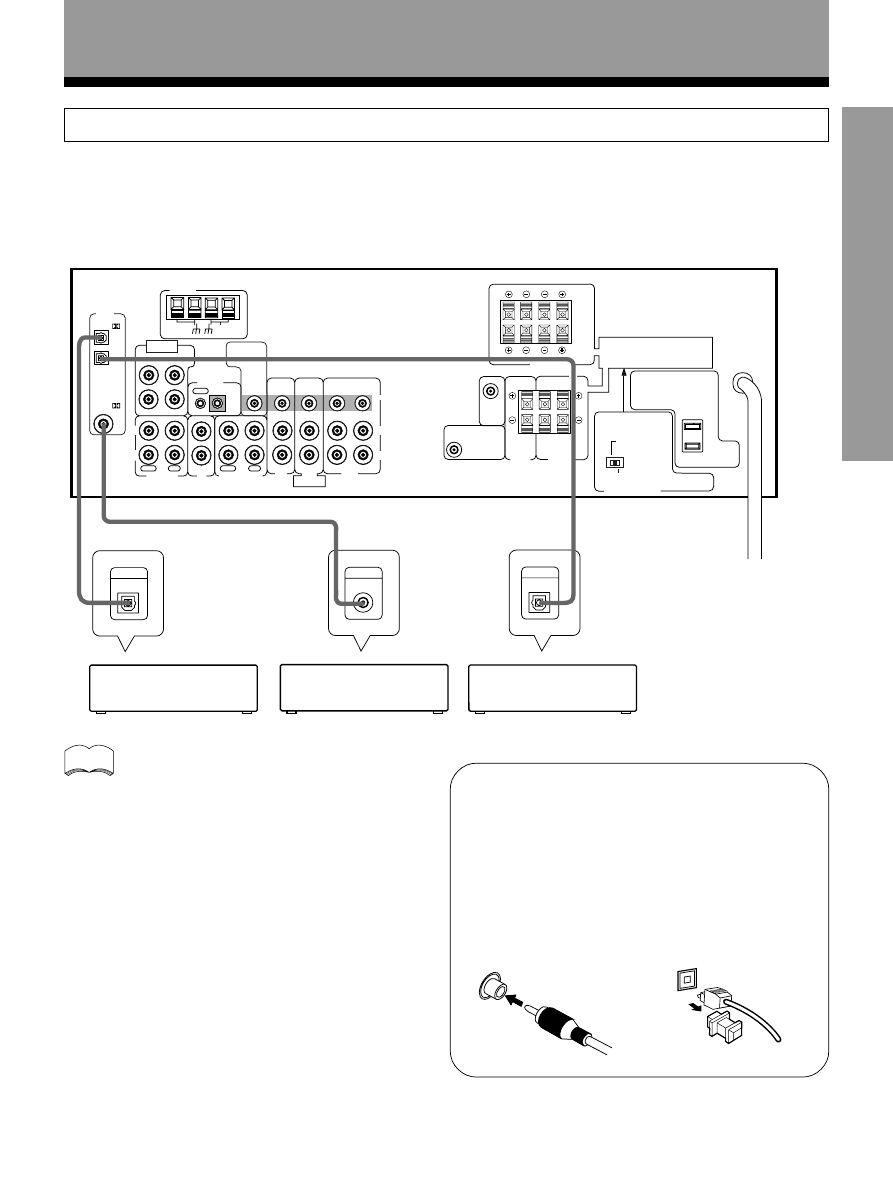
Digital Connections
Digital components can be connected as shown below. You can select up to three of the following be assigned to the
digital inputs on this unit: DVD/LD, TV/SAT, MD/TAPE1, CD, VCR. To assign the digital inputs, refer to “Setting Up for
Surround Sound” on page 15, 19)
When playing LD recorded in Dolby Digital
When connecting a DVD/LD player or LD player using
the AC-3 RF output, a commercially available RF
demodulator (RFD-1) is required. The RF demodulator
changes the RF signal to a digital signal which is then
processed by the receiver through the digital input
jacks. For more details, refer to the instruction manual
supplied with the RFD-1.
The factory setting for each of the digital inputs is
described below.
COAX : DVD
OPT 1 : CD
OPT 2 : MD
memo
7 Digital audio cords/Fiber-optic cables
Commercially available digital audio coaxial cord
(standard video cords can also be used) or fiber-optic
cables (not supplied) are used to connect digital
components to this receiver.
When you use optical digital input or output terminals,
pull off the caps and insert the plugs. Be sure to insert
completely.
Digital audio cord
(or standard video cord)
Fiber-optic cables
CD player
DVD player
MD recorder
Connections
12
<ARB7192>
VIDEO
OUT
FM
UNBAL
75
Ω
OUT
IN
CONTROL
LOOP
ANTENNA
AM
ANTENNA
OPT
1
OPT
2
COAX
PLAY
REC
MD/TAPE 1
IN
N
OUT
PLAY
REC
IN
IN
IN
IN
IN
IN
OUT
IN
OUT
OUT
CD
TAPE 2 M NITOR
TO
MONITOR
TV
R
L
TV/
SAT
DVD/
LD
DVD 5 1 CH
INPUT
SURROUND
L
R
CENTER
SUBWOOFER
VD 5 1 CH
FRONT
VCR
PCM/
PCM/
CENTER
PREOUT
SUB
WOOFER
PREOUT
L
L
R
R
B
A
SURROUND
SPEAKERS
CENTER
SPEAKER
CAUTION:
CAUTION:
SEE NSTRUCTION
MANUAL
8 16
Ω / SPEAKER
8 16
Ω / HAUT
PARLEUR
6 LESS THAN 8
Ω /SPEAKER
6 MOINS DE 8
Ω /HAUT PARLEUR
MPEDANCE SELECTOR
L
R
VIDEO
D GITAL
N
L
R
B
A
FRONT SPEAKERS
L
R
SPEAKER MPEDANCE
6
Ω OR 8Ω 16Ω / SPEAKER
ATTENTION:
IMPEDANCE DE HAUT PARLEURS
6
Ω OU 8Ω 16Ω / HAUT PARLEUR
ATTENTION:
SE REPOTER AU
MODE D EMPLON
L
R
SURROUND
OUTPUT
L
R
FRONT
OUTPUT
CENTER
VIDEO
OUT
SUB
WOOFER
»
»
»
» »
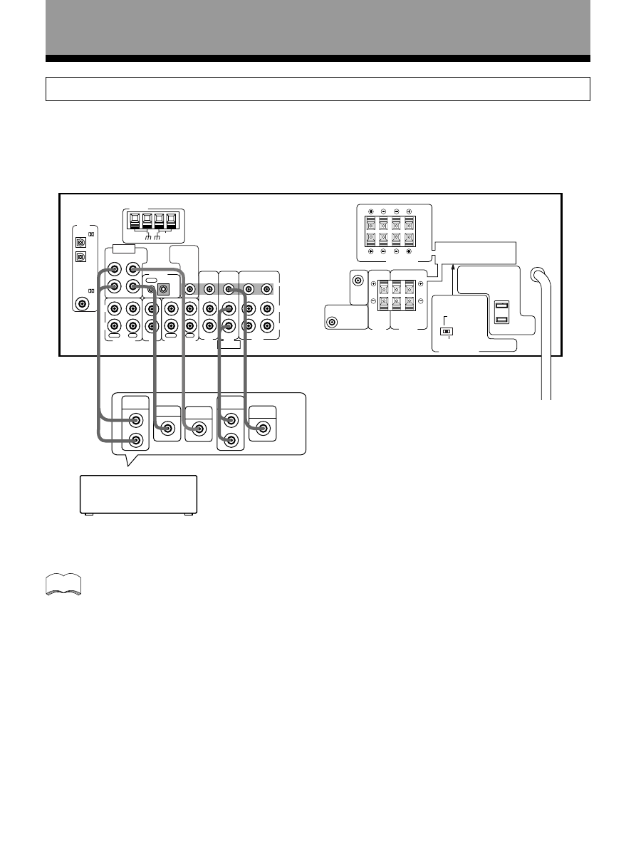
Connections
DVD 5.1 Channel Connection
DVD and LD discs are often compatible with both 2 channel and 5.1 channel audio output formats. Refer to page 30 for
more information on how to switch between the two input methods.
Connections can be made from a DVD player, Multi channel decoder equipped with 5.1 analog outputs to the 5.1 analog
inputs on this unit.
memo
The 5.1 channel input can only be used when DVD/LD is selected.
Components equipped
with 5.1 channel
analogue output jacks
13
<ARB7192>
SET UP
VIDEO
OUT
FM
UNBAL
75
Ω
OUT
IN
CONTROL
LOOP
ANTENNA
AM
ANTENNA
OPT
1
OPT
2
COAX
PLAY
REC
MD/TAPE 1
IN
N
OUT
PLAY
REC
IN
N
N
IN
N
IN
OUT
N
OUT
OUT
CD
TAPE 2 MONITOR
TO
MON TOR
TV
R
L
TV/
SAT
DVD/
LD
DVD 5 1 CH
INPUT
SURROUND
L
R
CENTER
SUBWOOFER
DVD 5 1 CH
FRONT
VCR
PCM/
PCM/
CENTER
PREOUT
SUB
WOOFER
PREOUT
L
L
R
R
B
A
SURROUND
SPEAKERS
CENTER
SPEAKER
CAUTION:
CAUTION:
SEE NSTRUCTION
MANUAL
8 16
Ω / SPEAKER
8 16
Ω / HAUT
PARLEUR
6 LESS THAN 8
Ω /SPEAKER
6 MOINS DE 8
Ω /HAUT PARLEUR
MPEDANCE SELECTOR
L
R
V DEO
D GITAL
IN
L
R
B
A
FRONT SPEAKERS
L
R
SPEAKER MPEDANCE
6
Ω OR 8Ω ~ 16Ω / SPEAKER
ATTENTION:
IMPEDANCE DE HAUT PARLEURS
6
Ω OU 8Ω ~ 16Ω / HAUT PARLEUR
ATTENT ON:
SE REPOTER AU
MODE D'EMPLON
NPUT
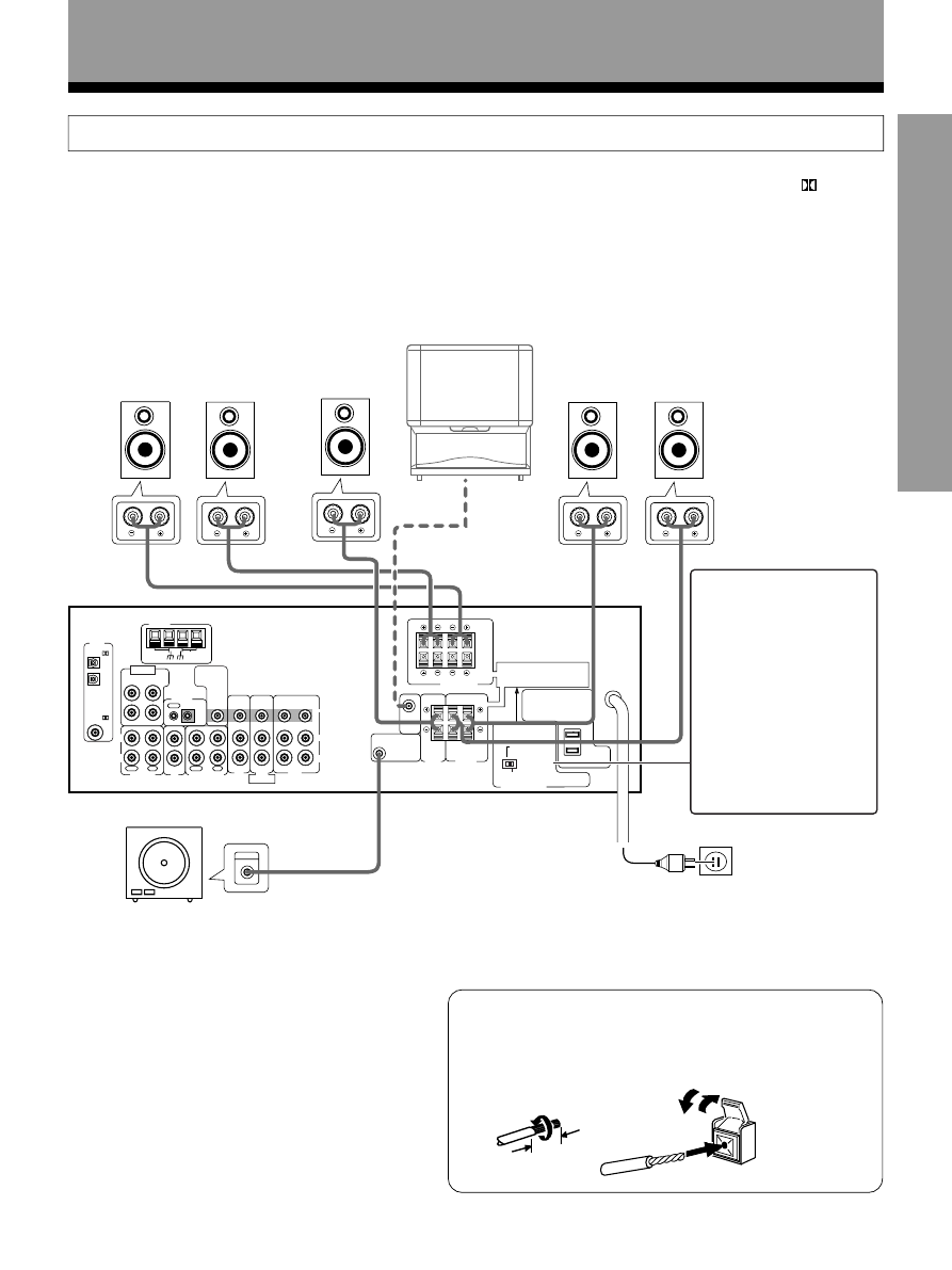
Speakers
Connections
• Use speakers with a nominal impedance of 6
Ω to 16 Ω.
• The front speaker B terminal is only used in stereo mode (Not available during DVD 5.1 channel, DSP mode,
(Dolby)
Surround mode).
• When you use the speaker on your TV as a center speaker, please connect the CENTER PREOUT jack on this unit to
the audio input jack on your TV. In this case, the center speaker shown below is unnecessary. Refer to the instruction
manual supplied with the TV or monitor you are connecting to for more information.
• You can set the configuration of your speaker system, whether the sizes of the speakers are large or small, and
whether or not you have a sub woofer connected. (Refer to pages 15 to 17)
• No sound is output from the front speakers if both A and B speaker systems are selected, but only one pair of
speakers is connected to the FRONT SPEAKERS terminals. To select the speaker system, refer to page 23.
7 Speaker terminals
Push tab to the open position, and
insert the wire. Then, close tab
firmly to secure the wire in place.
Front Speakers
Surround Speakers
Center Speaker
Be sure to complete all other
connections before connecting
this unit to the AC power source.
Amplified Sub Woofer
Twist exposed wire
strands together.
Connection methods that differ from the example
shown in this manual may be available. For more
details, refer to the instruction manual supplied with
the sub woofer.
TV
3/8 in.(10mm)
Sub Woofer
(To the audio input)
L
R
C
SL
SR
Use speakers with
nominal impedance of 6
Ω
to 8
Ω or 8 Ω to 16 Ω.
• When using speakers
with impedance of at
least 6
Ω but less than 8
Ω, set the IMPEDANCE
SELECTOR to the
“6~LESS THAN 8
Ω”
position.
• When using 8
Ω to 16 Ω,
set the IMPEDANCE
SELECTOR to “8~16
Ω”
position.
(To be used as the
center speaker)
14
<ARB7192>
• Install the left and right front speakers at equal distances from the TV.
• When installing speakers near the TV, we recommend using magnetically shielded speakers to prevent
possible interference such as distortion in the color of the TV screen. If you do not have magnetically
shielded speakers and notice discoloration of the TV screen, place the speakers farther away from the TV.
• Install the center speaker above, below the TV so that the sound of the center channel is localized at the TV
screen.
CAUTION:
When installing the center speaker on top of the TV, be sure to secure it with tape or some other suitable
means.
Otherwise, the speaker may fall from the TV due to external shocks such as earthquakes, and it may lead to
endangering those nearby or damaging the speaker.
• If possible, install the surround speakers slightly above ear level.
• It may be difficult to obtain a cohesive surround effect if the surround speakers are installed farther away
from the listening position than the front and center speakers.
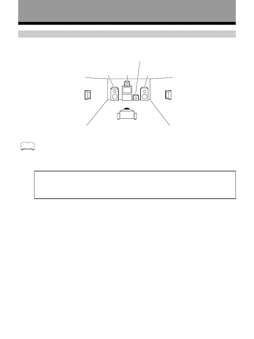
Speaker placement
To achieve the best possible surround sound, install your speakers as shown below. Be sure all speakers are installed
securely to prevent accidents and improve sound quality.
Connections
Surround
Left
Surround
Right
Listening
Position
Front
Left
Front
Right
Center
Sub Woofer
memo
15
<ARB7192>
SET UP
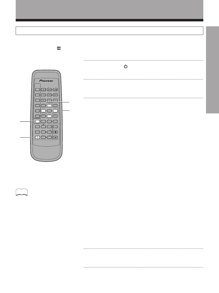
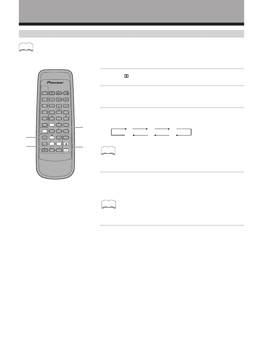
Preparations
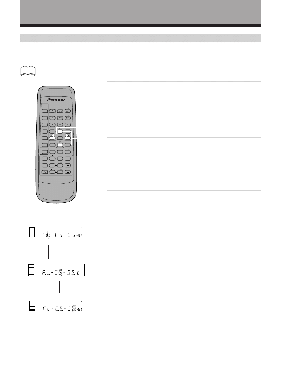
1
Press RECEIVER STANDBY/ON to turn the power on.
The STANDBY indicator goes out.
2
Press SURROUND.
This switches the remote to the surround setup mode.
3
Press
@ or # to select the mode you desire.
For best results, start with “SPEAKER setting mode” and make your
initial adjustments in the order described below.
The current settings are displayed automatically.
SPEAKER (Front, Center, Surround) setting mode (page 16)
Use to specify the type of speakers you have connected.
SUB WOOFER ON/OFF setting mode (page 17)
Use to specify the sub woofer as on or off.
Crossover frequency setting mode (page 17)
Use to determine which frequencies will be sent to the sub woofer or
“Large” speakers.
LFE attenuator setting mode (page 17)
Use to specify the peak level for the LFE channel and the crossover
network for rerouted bass frequencies.
Low cut filter ON/OFF setting mode (page 18)
Use to cut the distorted sound from the sub woofer.
FRONT speaker distance setting mode (page 18)
Use to specify the distance from your listening position to your front speaker.
CENTER speaker distance setting mode (page 18)
Use to specify the distance from your listening position to your center speaker.
SURROUND speaker distance time setting mode (page 18)
Use to specify the distance from your listening position to your surround speakers.
Dynamic range control setting mode (page 19)
Use to compress the dynamic range of the sound track.
Coaxial digital input setting (page 19)
Use to specify the input to be assigned to the coaxial digital input.
Optical digital input 1 setting (page 19)
Use to specify the input to be assigned to the optical digital input 1.
Optical digital input 2 setting (page 19)
Use to specify the input to be assigned to the optical digital input 2.
4
Press
% or fi to select the setting you desire.
The setting is entered automatically.
5
Repeat steps 3 and 4 to set other surround modes.
Setting Up for Surround Sound
Be sure to switch the power of this unit on (The STANDBY indicator goes out) before operating.
To ensure the best possible surround sound, be sure to complete the following set up operations. This is particularly
important when using the
(Dolby) Surround mode. You only need to make these settings once (unless you change
the placement of your current speaker system or add new speakers, etc.). Refer to the following pages for detailed
descriptions of the settings available for each mode.
1
2
4
• The setting mode is automatically exited
if no operation is performed for 20
seconds.
memo
3
AV MULTI-CHANNEL RECEIVER
REMOTE CONTROL UNIT
RECE VER
STANDBY/ON
LD
DVD
TUNER
MPX
STANDBY ON
CLASS
DIRECT
ACCESS
TAPE
TV FUNC
BAND
CD
SOURCE
SELECT
TEST TONE
EFFECT
SURROUND
DSP MODE
TV VOL
FREQ
0
7
5
1
3
MUTING
MASTER
VOLUME
Î
CD D SC
CHANNEL
STATION
TV
CONTROL
LEVEL
FUNCTION
CHANNEL
SELECT
ATT
6
2
4
8
16
<ARB7192>
Preparations
1
Press
% or fi to set the front speaker.
Front speaker (initial setting is “L (Large)”)
• Select “FL” if your speakers will reproduce bass frequencies effectively or
if you did not connect a sub woofer.
• Select “FS” to send bass frequencies to the sub woofer. (The center and
surround speakers cannot be set to Large if the front speakers are set to
Small. In this case, all bass frequencies are sent to the sub woofer.)
2
Press
% or fi to set the center speaker.
Center speaker (initial setting is “L (Large)”)
• Select “CL” if your speaker will reproduce bass frequencies effectively.
• Select “CS” to send bass frequencies to the other speakers or sub woofer.
• Select “C
∗
” if you did not connect a center speaker. In this case, the
center channel is output from the front speakers.
3
Press
% or fi to set the surround speaker.
Surround speaker (initial setting is “L (Large)”)
• Select “SL” if your speakers will reproduce bass frequencies effectively.
• Select “SS” to send bass frequencies to the other speakers or sub woofer.
• Select “S
∗
” if you did not connect surround speakers. In this case, the
sound of the surround channels is output from the front and center
speakers.
SPEAKER setting mode
Establishes the size and configuration of the speaker system you have connected.
In the display, “F”, “C”, and “S” refer to front, center, and surround speakers respectively. Speaker size is denoted as
“L” for large speakers, “S” for small speakers, and “
∗
” (asterisk) if no speaker is connected.
If the cone size of your speaker is larger than 5 inches (12 cm), please set to Large.
dB
SP
S GNAL
SELECT
ANALOG
A
dB
SP
SIGNAL
SELECT
ANALOG
A
dB
SP
SIGNAL
SELECT
ANALOG
A
2
2
2
2
memo
* Press
# to advance to the next
setting, and press
@ to return
to previous setting.
AV MULTI-CHANNEL RECEIVER
REMOTE CONTROL UNIT
RECE VER
STANDBY/ON
LD
DVD
TUNER
MPX
STANDBY ON
CLASS
DIRECT
ACCESS
TAPE
TV FUNC
BAND
CD
SOURCE
SELECT
TEST TONE
EFFECT
SURROUND
DSP MODE
TV VOL
FREQ
0
7
5
1
MUTING
MASTER
VOLUME
Î
CD D SC
CHANNEL
STATION
TV
CONTROL
LEVEL
FUNCTION
CHANNEL
SELECT
ATT
6
2
4
8
%,fi
@,#
17
<ARB7192>
SET UP
Preparations
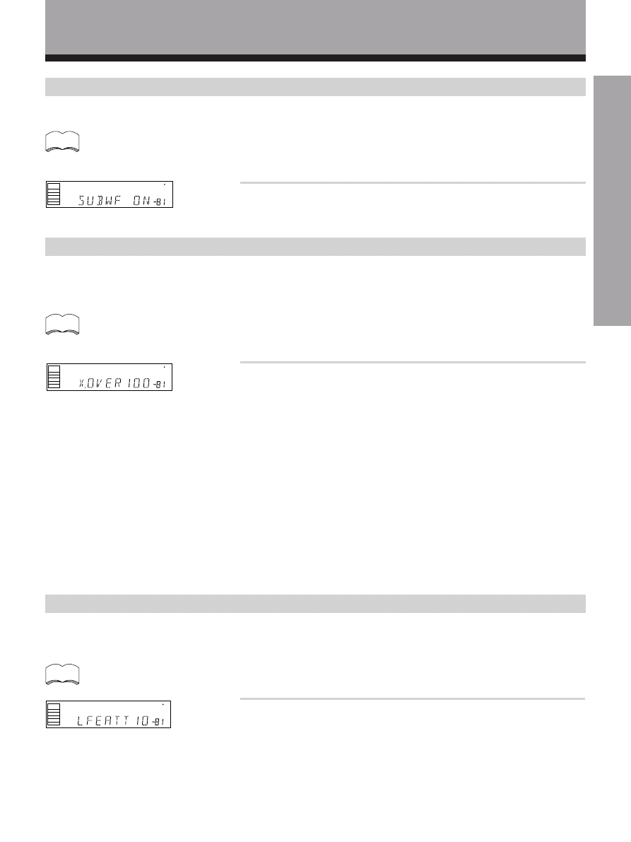
SUB WOOFER ON/OFF setting mode
Sets whether the SUB WOOFER is used or not.
• Initial setting is “ON”.
• Setting the front speaker size to “Small” in the SPEAKER setting mode automatically locks the sub woofer
in the “ON” position.
Press
% or fi to select sub woofer ON or OFF.
memo
Crossover frequency setting mode
Setting speakers to “Small” in “SPEAKER setting mode” sends the respective channels’ bass frequencies to the sub
woofer (or “Large” speakers). This function lets you determine which frequencies will be sent to the sub woofer or
“Large” speakers.
• Initial setting is “100 Hz”.
• If all speakers (front, center, and surround) are set to “Large” in SPEAKER setting mode, crossover
frequency cannot be set. (
∗∗∗
appears in the display.)
Press
% or fi to specify the crossover frequency for your small
speakers (100 Hz, 150 Hz or 200 Hz).
100 Hz
Sends bass frequencies below 100 Hz to the sub woofer (or Large
speakers).
150 Hz
Sends bass frequencies below 150 Hz to the sub woofer (or Large
speakers).
200 Hz
Sends bass frequencies below 200 Hz to the sub woofer (or Large
speakers). We recommend setting 200 Hz when only small speakers
are used.
memo
LFE attenuator setting mode
Dolby Digital audio sources include ultra-low bass tones. Set the LFE attenuator as needed to prevent the ultra-low
bass tones from distorting the sound from the speakers.
• Initial setting is “0 dB”.
• When
∞ is selected (
∗∗
appears in the display), LFE is not available.
memo
Press
% or fi to set the attenuation level (0 dB, 10 dB
or
∗∗
dB (
∞)).
dB
SP
SIGNAL
SELECT
ANALOG
A
dB
SP
SIGNAL
SELECT
ANALOG
A
dB
SP
S GNAL
SELECT
ANALOG
A
18
<ARB7192>
Preparations
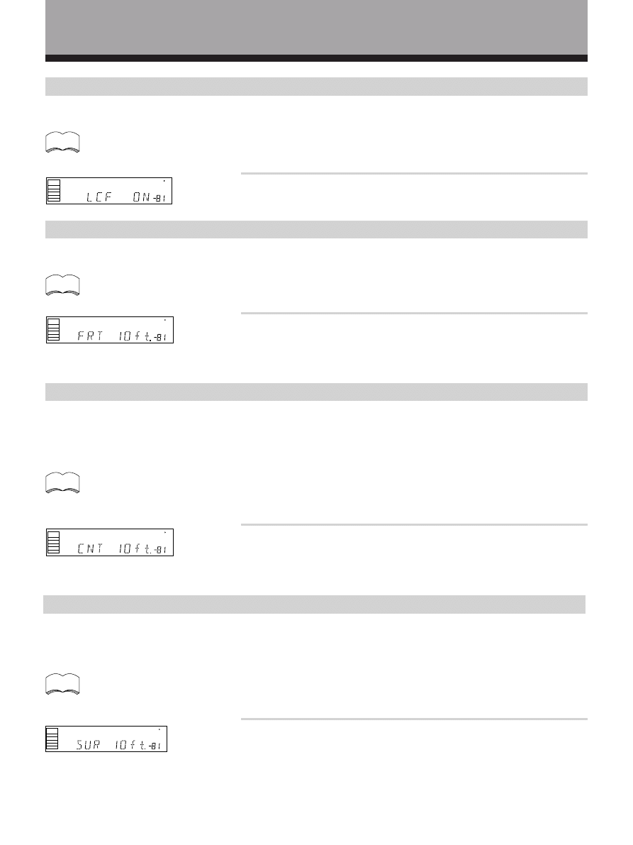
Low cut filter ON/OFF setting mode
Turn the low cut filter ON when distorted sound is output through the sub woofer.
• Initial setting is “OFF”.
• If the SUB WOOFER is set to “OFF” in the SUB WOOFER ON/OFF setting mode, the low cut filter cannot be
set.
Press
% or fi to select low cut filter ON or OFF.
memo
CENTER speaker distance setting mode
Normally as the Center speaker is placed directly in front in the listening room, it is closer to the listening position than
the Front speakers. This means that the sound from the Center speaker will be heard before the Front speakers. To
prevent this, set the Center speaker distance setting to delay the sound from the Center speaker so that the sound from
the Front and Center speakers will be heard at the same time.
• Initial setting is 10 feet.
• When “C
∗
” is selected in SPEAKER setting mode, the Center distance cannot be set.
• One step equals about 1 foot (30 cm).
Press
% or fi to set the distance of the CENTER speaker from
the main listening position (up to 30 steps).
memo
SURROUND speaker distance setting mode
Use to set the SURROUND speaker distance. Like the CENTER speaker position, the SURROUND speakers may be set
in a location closer or farther than the FRONT speakers. Set the distance of the SURROUND speakers accurately to hear
sounds coming from both FRONT and SURROUND speakers at the same time.
• Initial setting is 10 feet.
• When “S
∗
” is selected in SPEAKER setting mode, the SURROUND distance cannot be set.
• One step equals about 1 foot (30 cm).
Press
% or fi to set the distance of the SURROUND speaker
from the main listening position (up to 30 steps).
memo
FRONT speaker distance setting mode
Sets the distance from the FRONT speaker to the listening position.
• Initial setting is 10 feet.
• One step equals about 1 foot (30 cm).
dB
SP
SIGNAL
SELECT
ANALOG
A
memo
Press
% or fi to set the distance of the FRONT speaker from
the main listening position (up to 30 steps).
dB
SP
SIGNAL
SELECT
ANALOG
A
dB
SP
SIGNAL
SELECT
ANALOG
A
dB
SP
SIGNAL
SELECT
ANALOG
A
19
<ARB7192>
SET UP
Preparations
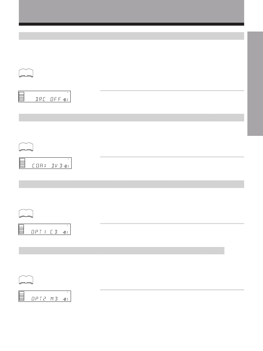
Dynamic range control setting mode
Dynamic range indicates in decibels how loud and soft sounds can be played back properly (so that soft sounds are not
covered by noise and loud sounds are not distorted). Dynamic range control is a function which compresses this
dynamic range. Even when watching a movie at low volume, setting this function enables low level sounds to be heard
more easily.
• Initial setting is “OFF”.
• When the volume level is increased, set to OFF.
• For listening enjoyment at low volumes, set to “MAX” for maximum dynamic range compression.
• Dynamic range control is effective only when a Dolby Digital signal is being played back.
Press
% or fi to set the dynamic range control (OFF, MAX or
MID).
memo
dB
SP
S GNAL
SELECT
ANALOG
A
Coaxial digital input setting
Sets the input component to be assigned to the coaxial digital input jack.
• Initial setting is “DVD”.
memo
Press
% or fi to select the coaxial digital input (DVD, TV, CD,
MD, VCR or OFF).
dB
SP
S GNAL
SELECT
ANALOG
A
Optical digital input 1 setting
Sets the input component to be assigned to the optical input 1 jack.
• Initial setting is “CD”.
memo
Press
% or fi to select the optical digital input 1 (DVD, TV, CD,
MD, VCR or OFF).
dB
SP
SIGNAL
SELECT
ANALOG
A
Optical digital input 2 setting
Sets the input to be assigned to the optical input 2 terminal.
• Initial setting is “MD”.
memo
Press
% or fi to select the optical digital input 2 (DVD, TV, CD,
MD, VCR or OFF).
dB
SP
SIGNAL
SELECT
ANALOG
A
20
<ARB7192>
1
Press
button.
2
Press VOL + or – to adjust the volume to an appropriate
level.
3
Press TEST TONE to output the test tone.
The test tone is output in the following order.
• Depending on the “SPEAKER setting mode” chosen, some
channels may not output test tone (refer to page 16).
• Test tone is only output in Dolby mode.
4
Adjust speaker levels so that you hear the test tone at
the same volume from each speaker when seated in the
main listening position.
The channel level ranges ± 10 dB.
• Levels can be set for each surround mode.
• When both the DSP mode and Dolby Surroud mode are turned
on, priority is given to the Dolby Surround mode.
5
Press TEST TONE to turn off the test tone.
• Sound from the SUB WOOFER seems quite.
• The speaker volume can be adjusted without outputting the test tone by pressing CHANNEL LEVEL or
CHANNEL SELECT .
• Initial setting is 0 dB.
FL
CT
FR
SR
SL
SW
memo
Setting the volume level of each channel (Adjusting the speaker volume balance)
1
2
3,5
4
memo
memo
AV MULTI-CHANNEL RECEIVER
REMOTE CONTROL UNIT
RECE VER
STANDBY ON
LD
DVD
TUNER
MPX
STANDBY ON
CLASS
DIRECT
ACCESS
TAPE
TV FUNC
BAND
CD
SOURCE
SELECT
TEST TONE
EFFECT
SURROUND
DSP MODE
TV VOL
FREQ
0
9
5
1
3
MUTING
MASTER
VOLUME
Î
CD DISC
CHANNEL
STATION
TV
CONTROL
LEVEL
FUNCTION
CHANNEL
SELECT
ATT
6
2
4
7
21
<ARB7192>
OPERA
TION
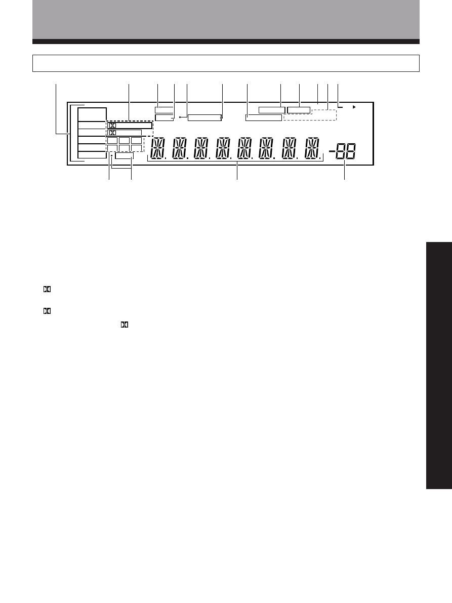
Names of Parts and Basic Operations
9 TAPE2 indicators
Lights when TAPE 2 MONITOR is on.
0 H.P indicator
Lights when headphones are plugged in.
- Tuner indicators
STEREO : Lights when an FM stereo broadcast is
received in the auto stereo mode.
TUNED : Lights when a broadcast is received.
MONO : Lights when the tuner is set to receive FM
broadcasts in monaural.
= Speaker indicators
Light to indicate the current speaker system (refer to
“Front Panel”, 7, SPEAKERS (A/B) on pages 23, 24).
SP
3 A : Lights when speaker system A is selected.
SP
3 B : Lights when speaker system B is selected.
~ Program format indicators
The following indicators light to show the channels
being played back.
L : Left front*
1
*
2
, C : Center*
1
, R : Right front*
1
*
2
,
LS : Left surround*
1
,S : Surround (mono)*
2
,
RS : Right surround*
1
*1: Indicates 5.1ch Dolby Digital playback.
*2: Indicates Dolby Pro Logic playback.
! LFE indicator
LFE (Low Frequency Effects) indicator lights to
indicate that the program source contains an LFE
channel. The indicator to the left of LFE lights during
actual playback of the LFE signals (LFE signals are not
present in all parts of the sound track).
@ Character display
# Volume level display
Displays the volume level. Volume level is maintained
even when the power is off. ---dB indicates the
minimum level, and 0dB indicates the maximum
level.
• Depending on the level settings for individual
channels, the MAX level can range between –10dB
and 0dB.
1 SIGNAL SELECT indicators
Light to indicate the type of input signal selected for
the current component (refer to “Front Panel”, !,
SIGNAL SELECT on pages 23, 24).
ANALOG : Lights when the analog audio signals are
selected.
DIGITAL : Lights when the digital audio signals are
selected.
AC-3 : Lights when a source with Dolby Digital signals
is played.
2 Digital indicators
PRO LOGIC : When the Dolby mode on the reciever
is on, this indicator lights during 2 channel playback
of Dolby Digital sources.
DIGITAL : When the Dolby mode on the reciever is
on, this indicator lights to indicate playback of a Dolby
Digital signal. However,
PRO LOGIC lights during 2
channel playback of Dolby Digital.
3 SFC (DSP) mode indicator
Lights when the DSP mode is selected.
(Refer to “Surround modes” on page 25)
4 ATT indicator
Lights when ATT (refer to “Remote Control”, 9,
Number buttons page 22) is used to reduce the level
of the input signal. (available in ANALOG mode only)
5 Overload indicator
When “ANALOG” is selected in SIGNAL SELECT, this
indicator lights when an excessively strong signal is
being processed . When this indicator lights, press
ATT on the remote control to attenuate (lower) the
signal and prevent distortion.
6 MIDNIGHT indicator
Lights when the MIDNIGHT mode is on.
7 LOUDNESS indicator
Lights when loudness is on (refer to “Front Panel”, -
,LOUDNESS on pages 23, 24).
8 DIRECT indicator
Lights when direct playback is on (refer to “Front
Panel”, (, DIRECT on pages 23, 24).
Display
dB
SP
SIGNAL
SELECT
ANALOG
DIGITAL
AC-3
PRO LOGIC
AB
DIGITAL
L
C
R
RS
S
LS
LFE
SFC
ATT
MIDNIGHT
LOUDNESS STEREO
H.P
MONO
TUNED
TAPE2
DIRECT
1
2
3
4 5
6
8
9
0
=
~
!
@
#
7
-
22
<ARB7192>
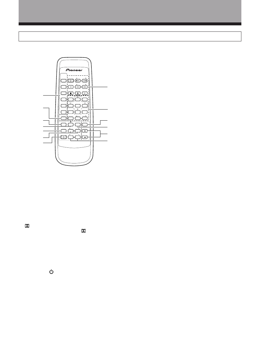
Remote Control
These pages describe the buttons on the remote control used to operate the receiver.
1 SOURCE SELECT buttons
Use these buttons to select the remote operation
mode.
For example, pressing TUNER sets the remote to
operate the tuner functions.
2 SURROUND button
Press to select the receiver for remote control
operation.
3 FUNCTION button
Press repeatedly to select a source.
4
Press repeatedly to select the
(Dolby) Surround
mode.
(refer to page 28)
5 CHANNEL SELECT
Use to select a speaker when adjusting speaker
levels.
6 LEVEL (–/+)
Use to adjust individual speaker levels.
7 RECEIVER STANDBY/ON button
Press to switch the receiver on or to put in standby.
8 TUNER operations
(press TUNER first)(refer to
page 32-35)
CHANNEL STATION
(+/–)
: Selects next /Previous
preset station.
TV FUNC.BAND : Switches between AM and FM
bands.
TV VOL.FREQ. :Changes the tuner frequency.
MPX : swiches between stereo and mono.
CLASS :changes preset bank(class)
DIRECT ACCESS : allows direct keying in of
Names of Parts and Basic Operations
AV MULTI-CHANNEL RECEIVER
REMOTE CONTROL UNIT
RECEIVER
STANDBY/ON
LD
DVD
TUNER
MPX
TANDBY/ON
CLASS
DIRECT
ACCESS
TAPE
V FUNC
BAND
CD
SOURCE
SELECT
TEST TONE
EFFECT
SURROUND
DSP MODE
TV VOL
FREQ
0
7
8
9
4
5
6
1
2
3
MUTING
MASTER
VOLUME
Î
CD D SC
CHANNEL
STATION
TV
CONTROL
LEVEL
FUNCTION
CHANNEL
SELECT
ATT
1
2
3
4
5
6
7
8
9
0
-
=
~
frepuency.
9 Number buttons/Surround setting buttons
These buttons can perform a variety of different
functions depending on the remote operation mode.
• [RECEIVER operations (press SURROUND first)]
%˜fi˜@˜# buttons : Specific use of these buttons is
described in conjunction with the operations they are
used in.
TEST TONE : Press to switch the test tone on or off
when listening to a surround mode (refer to page 20).
ATT : Press to attenuate (lower) the level of the input
signals and prevent distortion (refer to “Display”, 5,
Overload indicator on page 21).
• [TUNER operations (press TUNER first)]
Number buttons (0~9) : During preset tuning, use to
input the number of the preset station. Use to input
the station frequency during direct tuning.
0 MUTING button
Press to mute the volume. “MUTING” appears in the
display. Press again to cancel.
- DSP MODE
Press repeatedly to select a DSP sound mode (refer to
page 29).
= MASTER VOLUME(+/–) buttons
Press to adjust the volume. When VOL (+/–) buttons
are pressed while muting, muting is canceled.
~ EFFECT (+/–)
Use to adjust the DSP mode effect level.
23
<ARB7192>
OPERA
TION
STANDBY/ON
STANDBY
PHONES
AUDIO VIDEO M
LTI-CHANNEL RE
EIVER
VSX-D498
STATION
TUNING
SELECT
SIGNAL
SELECT
MIDNIGHT
DOWN
UP
BASS
TREBLE
VCR
DVD/LD
TV/SAT
VIDEO
CD
FM/AM
MD/TAPE 1
B
LOUDNESS
TAPE 2
MONITOR
DIRECT
V DEO
VIDEO
NPUT
L
MASTER
VOLUME
CL
SS
MEMORY
MPX
M
DE
+
+
–
+
–
+
–
–
FREQUENCY
D P
MO E
AUDIO
R
A
SPEAKERS
DVD 5 1CH
1
%
^
(
)
*
2
3 4 5 6 7
8
9
0
- = ~ ! @ #
$
&
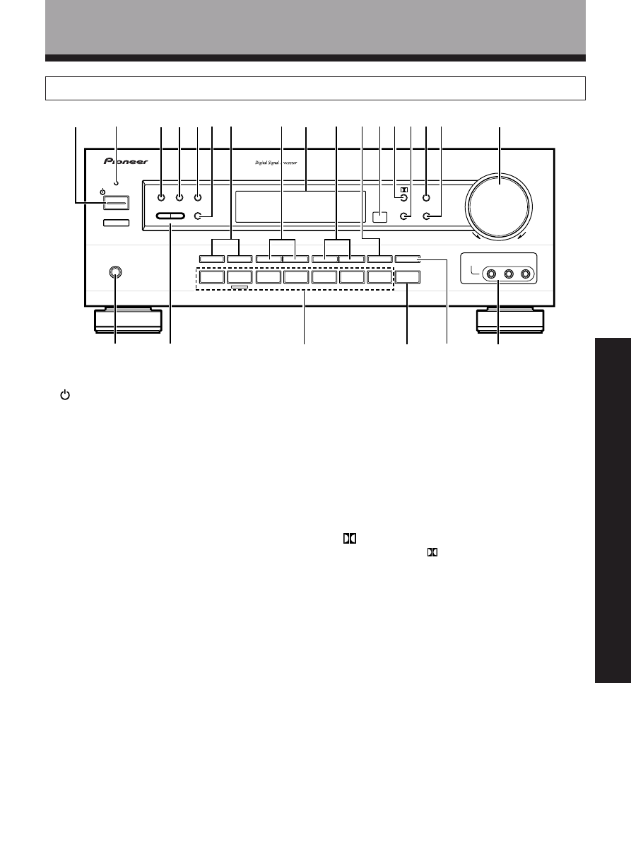
Names of Parts and Basic Operations
Front Panel
1
STANDBY/ON button
Press to switch the receiver on or put in standby.
2 STANDBY indicator
Lights when the receiver is in standby mode. (Please
note that this receiver consumes a small amount of
power (2.5 W) during the standby mode.)
3 CLASS button
Press repeatedly to switch the preset station classes.
(Refer to “Memorizing Frequency Tuned Stations” on
page 34 and “Recalling the Memorizing Stations” on
page 35)
4 MEMORY button
Press to memorize a preset station.
(Refer to “Memorizing Frequency Tuned Stations” on page
34)
5 MPX MODE button
Press to switch between auto stereo and monaural
(“MONO”) reception of FM broadcasts. When the
broadcast signal is weak, selecting “MONO” will
improve the sound quality.
6 TUNING SELECT button
Press to switch between STATION and FREQUENCY.
7 SPEAKERS (A/B) buttons
Use to switch the corresponding speaker system on
or off. To listen to both speaker systems (A and B),
press the buttons so that both A and B appear in the
display (refer to “Display”, =, Speaker indicators on
page 21). Only A speakers are available when using
surround sound modes.
8 BASS (+/–) button
Press to adjust low frequencies in the range of ±6.
9 Display (Refer to page 21)
0 TREBLE (+/–) button
Used to adjust high frequencies in the range of ±6.
- LOUDNESS button
Switches the loudness on or off. Use to raise the level
of the bass and treble frequencies so they can be
more easily heard when listening at low volumes.
= Remote sensor
Point the remote control toward the remote sensor to
operate the receiver.
~
button
Press to select the
(Dolby) Surround mode. This
mode automatically switches between Dolby Digital
and Dolby Pro Logic decoding according to the input
signal. (Refer to page 28 for more information about
Dolby Digital.)

24
<ARB7192>
Names of Parts and Basic Operations
! SIGNAL SELECT button
Use to select input signals for the digital components.
First press DVD/LD, TV/SAT, MD/TAPE 1, CD or VCR
(& Function buttons) to select the component, then
press SIGNAL SELECT repeatedly to select one of the
following:
ANALOG : Selects the analog (R and L) audio signals.
DIGITAL : Selects the digital audio signals. This
receiver automatically detects and displays the
format of the signal being input. AC-3 lights when
Dolby Digital signals are input. (Dolby Digital
decoding is switched automatically.)
• SIGNAL SELECT is fixed in the “ANALOG” position
for components not assigned to one of the three
digital input jacks.
• Because the audio from a karaoke microphone and
LD recorded with analog audio only is not output
from the digital output, set SIGNAL SELECT to
“ANALOG”.
• This receiver can only play back Dolby Digital, PCM
(32kHz, 44kHz, and 48kHz),digital signal formats.
With digital signal formats other than these, set
SIGNAL SELECT to “ANALOG”.
@ DSP MODE button
Press repeatedly to select a DSP sound mode (HALL 1,
HALL 2, JAZZ, DANCE, THEATER 1, or THEATER 2).
Use these modes to produce surround sound from
standard (two channel) stereo sources.
# MIDNIGHT button
Press to hear effective surround sound at low volume
levels. The effect is automatically adjusted according
to the volume level.
$ MASTER VOLUME
After turning on the desired component, rotate to
adjust the volume.
% PHONES jack
Connect headphones for private listening (the
speakers turn off automatically).
^ STATION/FREQUENCY (+/–) button
STATION: Press to select the preset channel.
FREQUENCY: Press to select the frequency.
& Function buttons
Selects the function. Each press switches the DVD/LD
input between DVD/LD and DVD 5.1 channel.
* TAPE 2 MONITOR button
Switches the TAPE 2 monitor on or off (refer to page 36).
( DIRECT button
Switches direct playback on or off. Use to bypass the
receiver’s tone control circuitry or level control for
higher fidelity to the program source. When DIRECT
is ON, Dolby, DSP, LOUDNESS and MIDNIGHT mode
are automatically turned OFF.
) VIDEO INPUT jacks
Connect a video camera, video game system, etc. to
the VIDEO INPUT jacks (refer to page 10).

25
<ARB7192>
OPERA
TION
Sound Modes
This receiver incorporates two surround modes for enjoyment of a variety of program sources.
Surround modes
(Dolby) Surround mode
Use this mode when playing Dolby Digital or Dolby Surround software. Decoding switches automatically according to
the input signal, so all you have to do is enjoy!
You can identify Dolby Digital software by the
DOLBY
D I G I T A L
or
A C 3 D
I
G
I
T
A
L
marks. Most Dolby Surround software is marked
DOLBY SURROUND
, but unmarked software may also incorporate Dolby Pro Logic.
For more information about Dolby formats, refer to page 43.
DSP modes
The DSP (Digital Sound Processing) modes allow you to transform your living room into a variety of different sonic
environments when playing standard (two-channel) stereo sources, Dolby Surround sources, and Dolby Digital
sources.
HALL 1
Simulates the acoustic environment of a large concert hall of wooden construction. Complex delay of reflected
sounds coupled with reverberation effects create a dynamic and beautiful sound characteristic of an orchestra
performing in a concert hall, making it suitable for classical music
HALL 2
Simulates the acoustic environment of a large concert hall with stone walls. The rich reverberations and natural
fullness of the sound create the auditory impression of being in a concert hall, making it suitable for classical music.
JAZZ
Simulates the acoustic environment of a jazz club. Less delay on the reflected sounds emphasizes the sensation of
hearing a live band.
DANCE
Simulates the acoustic environment and strong bass sound of a nightclub with a square dance floor. A short delay
on the reflected sounds emulates the raw power of the dance music.
THEATER 1
Adjusts the delay of the reflected sound to simulate the acoustic environment of a medium sized movie theater.
THEATER 2
Simulates the acoustic environment of a theater while maintaining proper localization of each channel.
26
<ARB7192>
Switching ANALOG/DIGITAL Signal Input
The input of the component set in the digital input setting (refer to page 19) can be switched to an analog or digital
input signal by pressing the SIGNAL SELECT button.
1
Press SIGNAL SELECT on the front panel to select the
input signal corresponding to the source component.
Each press switches between ANALOG and DIGITAL signal selection.
2
memo
SIGNAL SELECT
Sound Modes
SP
SIGNAL
SELECT
ANALOG
SIGNAL
SELECT
ANALOG
A
SP
SIGNAL
SELECT
DIG TAL
SIGNAL
SELECT
DIGITAL
A
While SIGNAL SELECT is set to DIGITAL, AC-3 lights when a Dolby
Digital signal is input.
When a Dolgy Digital signal is input.
SP
S GNAL
SELECT
D GITAL
AC-3
SIGNAL
SELECT
DIGITAL
AC-3
A
• SIGNAL SELECT is fixed in the “ANALOG” position for components not
assigned to one of the three digital input jacks.
• Because the audio from a karaoke microphone and LD recorded with
analog audio only is not output from the digital output, set SIGNAL
SELECT to “ANALOG”.
• This receiver can only play back Dolby Digital, PCM (32kHz, 44kHz, and
48kHz), digital signal formats. With digital signal formats other than these,
set SIGNAL SELECT to “ANALOG”.
27
<ARB7192>
OPERA
TION
Playback
1
Turn on the power of the playback component.
2
Press RECEIVER STANDBY/ON to turn on the receiver.
Be sure that the standby indicator turns off on
the front panel.
3
Press FUNCTION to select the source you want to
playback.
The source you want to playback is displayed in the following order:
4
Press SIGNAL SELECT on the front panel to select the
input signal corresponding to the source component.
(Refer to “Switching ANALOG/DIGITAL signal input” on page 26.)
5
Start playback of the component you selected in step 1.
6
Press VOL (+/–) to adjust the volume level in the range of
--- dB (MIN) to 0 dB (MAX).
2
3
6
3
2
6
STANDBY
indicator
• Depending on the channel level setting, the MAX volume level
may differ 0 to -10 dB from the level displayed.
memo
TUNER
MD/TAPE 1
VCR
TV/SAT
DVD/LD
VIDEO
CD
4
AV MULTI-CHANNEL RECEIVER
REMOTE CONTROL UNIT
RECEIVER
STANDBY/ON
LD
DVD
TUNER
MPX
STANDBY/ON
CLASS
D RECT
ACCESS
TAPE
TV FUNC
BAND
CD
SOURCE
SELECT
TEST TONE
EFFECT
SURROUND
DSP MODE
TV VOL
FREQ
0
9
5
1
3
MUTING
MASTER
VOLUME
Î
CD DISC
CHANNEL
STATION
TV
CONTROL
LEVEL
FUNCTION
CHANNEL
SELECT
ATT
6
2
4
7
Sound Modes
28
<ARB7192>
Playing Sources with Dolby Digital Sound
Sound Modes
1
Follow steps 1 to 3 of the playback procedure. (Refer to
“Playback” on page 27.)
1 Turn on the power of the playback component.
2 Press RECEIVER STADBY/ON to turn on the receiver.
3 Press FUNCTION to select the source component you want to play.
2
Press SIGNAL SELECT on the front panel to select
DIGITAL.
(Refer to “Switching ANALOG/DIGITAL signal input” on the previous
page.)
3
Press
to switch the Dolby Surround mode on.
4
Start playback of the component you selected in step 1.
5
Press VOL (+/–) to adjust the volume level.
3
5
2
3
5
When playing LD recorded in Dolby Digital
When connecting a DVD/LD player or LD player using the AC-3 RF output, a commercially available RF demodulator
(RFD-1) is required. The RF demodulator changes the RF signal to a digital signal which is then processed by the
receiver at the digital input jacks. For more details, refer to the instruction manual supplied with the RFD-1.
Refer to pages 43 for explanations Dolby Digital, Dolby Pro Logic.
memo
AV MULTI-CHANNEL RECEIVER
REMOTE CONTROL UNIT
RECEIVER
STANDBY/ON
LD
DVD
TUNER
MPX
STANDBY/ON
CLASS
D RECT
ACCESS
TAPE
TV FUNC
BAND
CD
SOURCE
SELECT
TEST TONE
EFFECT
SURROUND
DSP MODE
TV VOL
FREQ
0
9
5
1
3
MUTING
MASTER
VOLUME
Î
CD DISC
CHANNEL
STATION
TV
CONTROL
LEVEL
FUNCTION
CHANNEL
SELECT
ATT
6
2
4
7
29
<ARB7192>
OPERA
TION
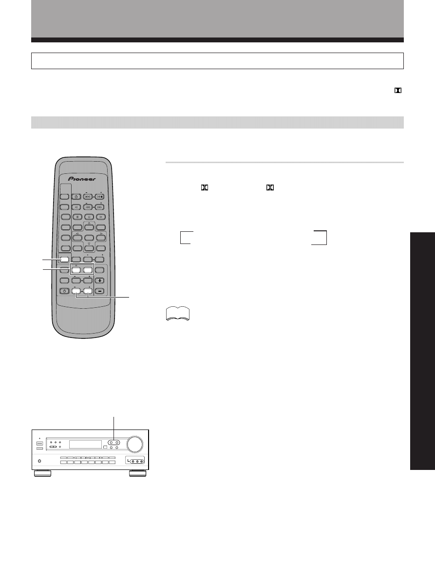
Select the sound mode.
• For
(Dolby)
\ Press
• For DSP modes
\ Press DSP MODE repeatedly
Each press changes the DSP mode as follows:
Selecting a Sound Mode
To ensure the best possible surround sound, be sure to complete the set up procedures described in “Setting Up for
Surround Sound” (starting on page 15) before using the sound modes. This is particularly important when using the
(Dolby) Surround mode. When using the sound modes, SPEAKERS A are used. If SPEAKERS B are selected and a
sound mode is turned on, selection automatically switches to SPEAKERS A only.
Surrround operation
Sound Modes
=HALL 1 = HALL 2 = JAZZ = DANCE
SFC OFF
+ THEATER 2 + THEATER 1 +
memo
• The amount of effect of each DSP mode can be adjusted in the range of 10
to 90 (the default setting value is 70) by pressing EFFECT +/–.
• Dolby Digital or Dolby Srround sources can be used simultaneously with
DSP modes.
1
2
EFFECT +/–
2
AV MULTI-CHANNEL RECEIVER
REMOTE CONTROL UNIT
RECEIVER
STANDBY ON
LD
DVD
TUNER
MPX
TANDBY ON
CLASS
DIRECT
ACCESS
TAPE
TV FUNC
BAND
CD
SOURCE
SELECT
TEST TONE
EFFECT
SURROUND
DSP MODE
TV VOL
FREQ
9
5
1
3
MUTING
MASTER
VOLUME
Î
CD D SC
CHANNEL
STATION
TV
CONTROL
LEVEL
FUNCTION
CHANNE
SELECT
ATT
6
2
4
7
30
<ARB7192>
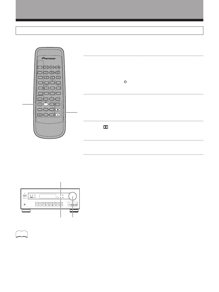
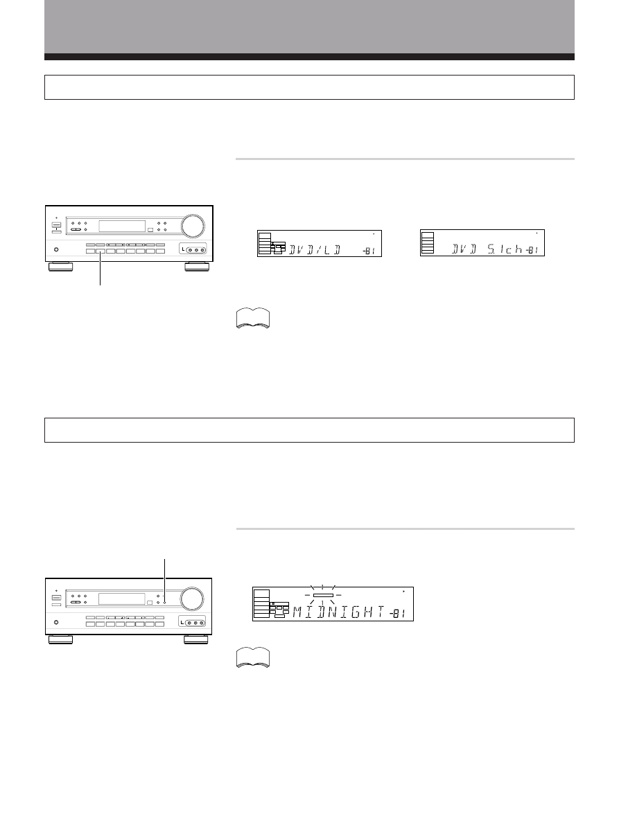
Listening in MIDNIGHT Listening Mode
When the volume is low, surround effects tend to become less than satisfactory. Turn the MIDNIGHT listening mode on
to enjoy the effects of quality surround sound even at low volumes. This mode allows you to hear effective surround
sound of movies at low volume levels.
Press MIDNIGHT.
Each press switches MIDNIGHT listening mode on or off.
dB
SP
SIGNAL
SELECT
DIGITAL
AC 3
A
DIGITAL
L
C
R
RS
LS
LEF
MIDNIGHT
memo
The effect automatically adjusts according to the volume level.
MIDNIGHT
DVD 5.1ch Input Playback
Connect a component with 5.1 channel output to enjoy the surround sound created by 5.1 channel playback.
Press DVD/LD on the unit.
Each press switches the input: DVD/LD
j DVD 5.1ch
dB
SP
SIGNAL
SELECT
ANALOG
A
dB
SP
SIGNAL
SELECT
D GITAL
AC-3
A
DIG TAL
L
C
R
RS
LS
LEF
j
memo
• When DVD 5.1ch input is selected, Dolby Surround mode, DSP
mode, SIGNAL SELECT, ATT, DIRECT, TONE, MIDNIGHT mode,
and speakers B cannot be operated.
• When DVD 5.1ch input is selected, only the volume level and
channel levels can be set.
DVD/LD
Sound Modes
31
<ARB7192>
OPERA
TION
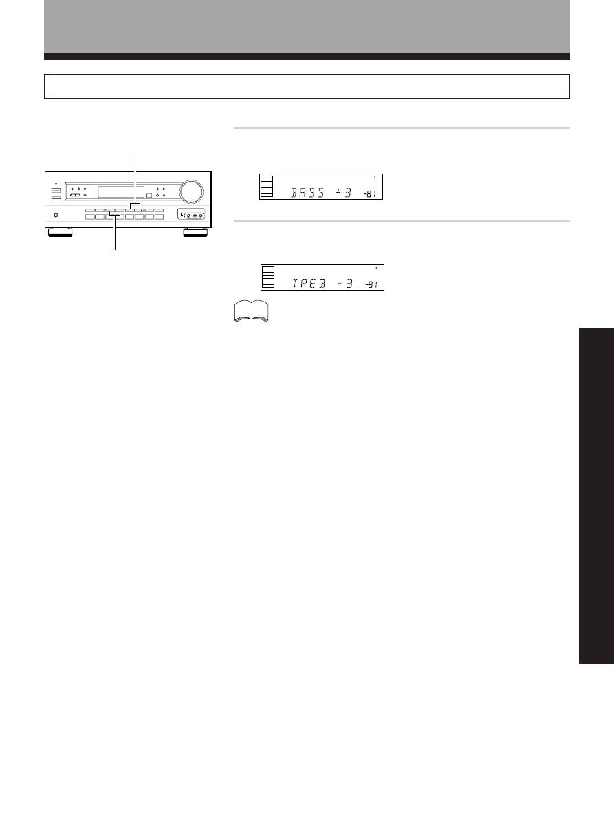
Adjusting Bass and Treble Frequencies (Tone Control)
Use BASS (+/–) or TREBLE (+/–) to adjust the low and high frequencies.
Press BASS (+/–) to adjust the low frequencies.
Press TREBLE (+/–) to adjust the high frequencies.
dB
SP
SIGNAL
SELECT
ANALOG
A
dB
SP
SIGNAL
SELECT
ANALOG
A
TREBLE +/–
BASS +/–
memo
• The tone control can be adjusted in a range of ±6.
• Pressing + and – simultaneously restores the setting to 0.
• In cases described below, the tone control cannot be adjusted.
1 Dolby Surround mode is ON.
2 DSP mode is ON.
3 DVD 5.1ch input is selected.
4 Dolby Digital signals are being input.
Sound Modes
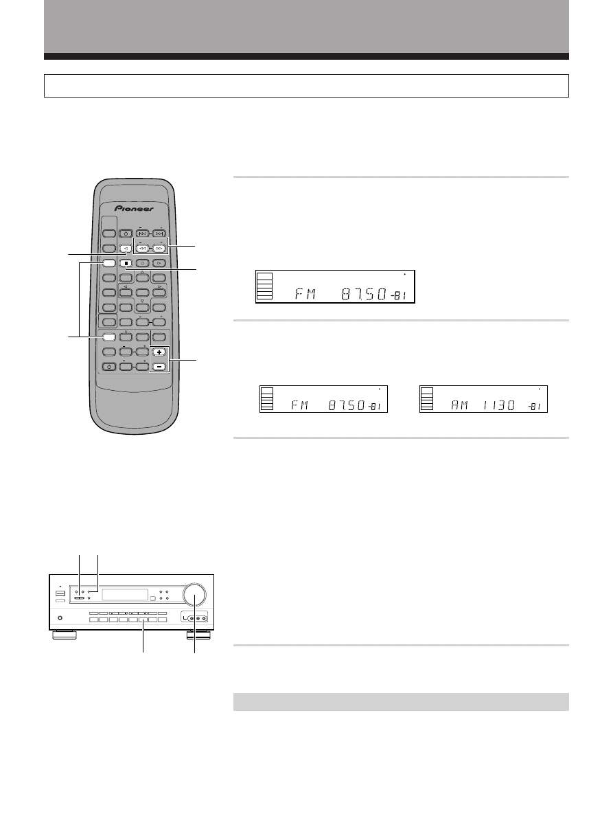
32
<ARB7192>
Tuner Operations
Automatic and Manual Tuning
The following steps show you how to tune in FM and AM radio broadcasts using the automatic (search) and manual
(step) tuning functions. If you already know the exact frequency of the station you want, see “Direct Tuning” on the
following page.
1
Press FUNCTION repeatedly on the remote or FM/AM on
the front panel to select the tuner. Press TUNER to set
the remote to the tuner operation mode.
The station you were previously tuned to is received automatically.
2
Press TV FUNC.BAND on the remote or FM/AM on the
front panel to select the band (FM or AM).
Each press switches the band: FM
j AM
3
Tune in the station.
For Automatic Tuning
Press and hold TV VOL.FREQ.(+/– ) for about one second, then release.
The tuner starts searching the selected band and stops automatically at
the first station it locates. Repeat to locate other stations.
For Manual Tuning
• To change frequencies one step at a time, press TV VOL.FREQ.(+/– )
repeatedly.
• To change frequencies quickly, hold down TV VOL.FREQ.(+/– ) and
release when you reach the frequency you want.
When using the front panel
Press FREQUENCY (+/–) until the frequency you want appears in the
display.
4
Adjust the volume.
MPX Mode
If the TUNED or STEREO indicators do not light when tuning an FM station,
because the station is too far away or the broadcast signal is weak, press
MPX MODE on the front panel to switch to monaural (MONO) reception.
This should improve reception enough for you to enjoy the broadcast.
1
2
3
4
j
2
4
3
MPX MODE
dB
SP
SIGNAL
SELECT
ANALOG
A
dB
SP
SIGNAL
SELECT
ANALOG
A
dB
SP
S GNAL
SELECT
ANALOG
A
AV MULTI-CHANNEL RECEIVER
REMOTE CONTROL UNIT
RECE VER
STANDBY ON
LD
DVD
TUNER
MPX
STANDBY ON
CLASS
DIRECT
ACCESS
TAPE
TV FUNC
BAND
CD
SOURCE
SELECT
TEST TONE
EFFECT
SURROUND
DSP MODE
TV VOL
FREQ
0
7
9
5
1
3
MUTING
MASTER
VOLUME
Î
CD DISC
CHANNEL
STATION
TV
CONTROL
LEVEL
FUNCTION
CHANNEL
SELECT
ATT
6
2
4
MPX
MODE
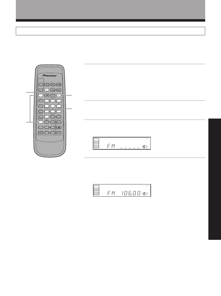
33
<ARB7192>
OPERA
TION
Tuner Operations
Direct Tuning
The following steps show you how to tune directly to a specific frequency using the remote control.
1
Press FUNCTION repeatedly on the remote or FM/AM on
the front panel to select the tuner. Press TUNER to set
the remote to the tuner operation mode.
The station you were previously tuned to is received automatically.
2
Press TV FUNC.BAND to select the band (FM or AM).
Each press switches the band: FM
j AM
3
Press DIRECT ACCESS to activate the direct tuning mode.
The cursor blinks in the display on the front panel.
4
Use the number buttons to enter the frequency of the
station you want.
Example:
To tune station 106.00 (FM), press: 1
= ` = 6 = ` = `
To cancel before inputting the frequency
Press DIRECT ACCESS, and enter the frequency again.
2
1
3
4
dB
SP
S GNAL
SELECT
ANALOG
A
dB
SP
SIGNAL
SELECT
ANALOG
A
AV MULTI-CHANNEL RECEIVER
REMOTE CONTROL UNIT
RECE VER
STANDBY/ON
LD
DVD
TUNER
MPX
STANDBY ON
CLASS
DIRECT
ACCESS
TAPE
TV FUNC
BAND
CD
SOURCE
SELECT
TEST TONE
EFFECT
SURROUND
DSP MODE
TV VOL
FREQ
MUTING
MASTER
VOLUME
Î
CD DISC
CHANNEL
STATION
TV
CONTROL
LEVEL
FUNCTION
CHANNEL
SELECT
ATT
0
9
3
6
2
4
8
1
5
7
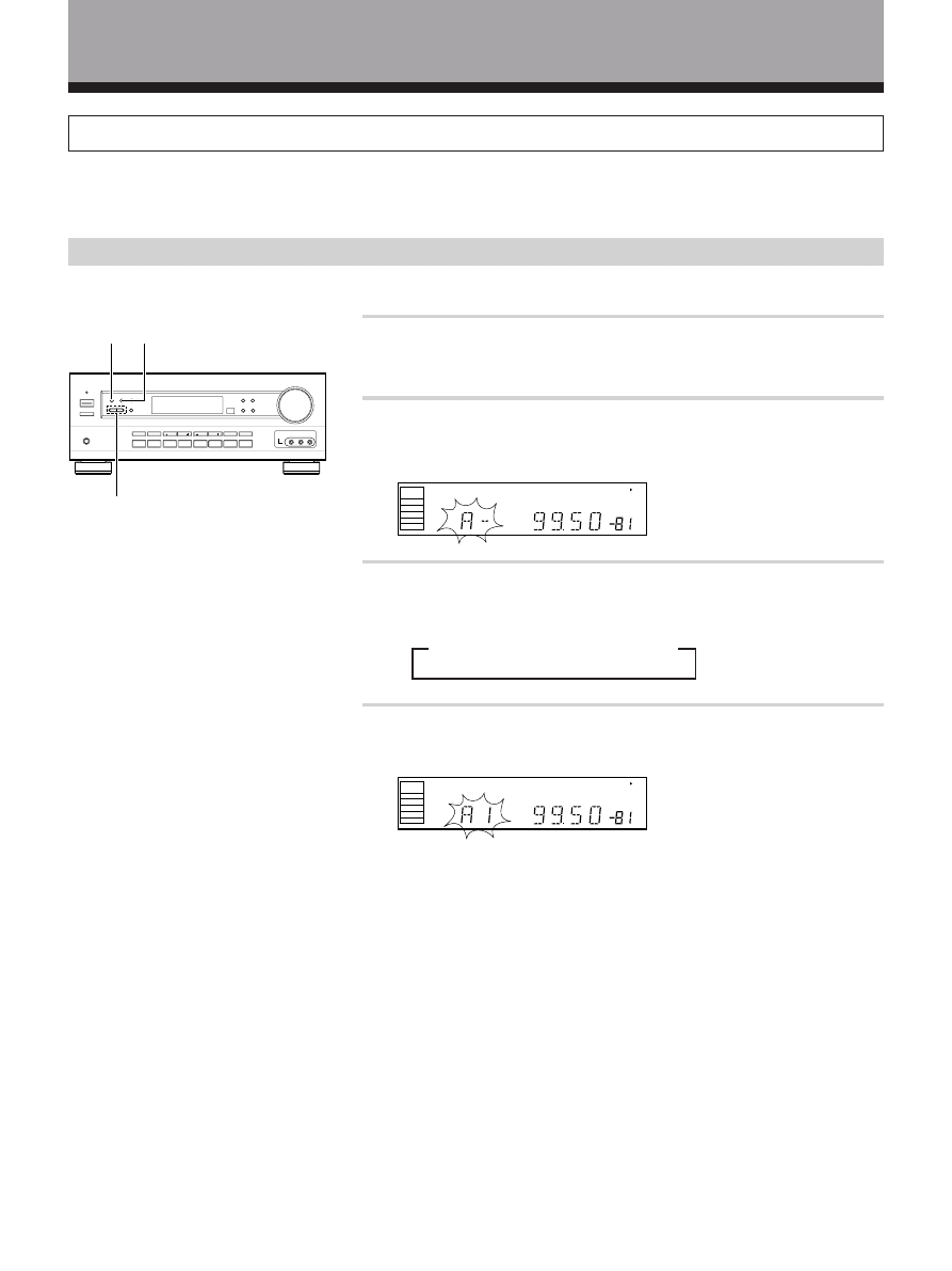
34
<ARB7192>
Tuner Operations
Memorizing Frequently Tuned Stations
The following steps show you how to memorize up to 30 radio stations in 3 classes (each holding 10 channels). When
memorizing FM frequencies, the receiver also memorizes the MPX mode (STEREO or MONO).
Using the front panel
1
Tune to the desired station.
See “Automatic and Manual Tuning” or “Direct Tuning” on pages 32, 33.
2
Press MEMORY to activate the memory function.
“A--” blinks in the display.
3
Press CLASS repeatedly to select a class.
Each press switches the display:
4
Press STATION (+/–) to select a channel (1~10) within the
respective class.
The station is memorized automatically after 5 seconds.
Repeat steps 1 through 4 to memorize up to 30 stations.
= CLASS A = CLASS B = CLASS C
2
3
4
dB
SP
SIGNAL
SELECT
ANALOG
A
dB
SP
SIGNAL
SELECT
ANALOG
A

35
<ARB7192>
OPERA
TION
Tuner Operations
Recalling the Memorized Stations
1
Press FUNCTION repeatedly on the remote or FM/AM on
the front panel to select the tuner. Press TUNER to set
the remote to the tuner operation mode.
The station you were previously tuned to is received automatically.
2
Press CLASS repeatedly to select a class.
Each press switches the display:
3
Use the number buttons to select the channel you want.
To select channel 7, press 7.
To select channel 10, press `.
For example : If 99.50 MHz (FM) was memorized in class B at channel 7.
To skip through each channel in order
Press STATION +/– repeatedly.
Using the remote control
Using the front panel
1 Press FM/AM.
2 Press CLASS repeatedly to select a class.
3 Press STATION +/– to select the channel you want.
= CLASS A = CLASS B = CLASS C
2
1
3
dB
SP
S GNAL
SELECT
ANALOG
A
dB
SP
SIGNAL
SELECT
ANALOG
A
2
1
3
AV MULTI-CHANNEL RECEIVER
REMOTE CONTROL UNIT
RECEIVER
STANDBY ON
LD
DVD
TUNER
MPX
STANDBY/ON
CLASS
DIRECT
ACCESS
TAPE
TV FUNC
BAND
CD
SOURCE
SELECT
TEST TONE
EFFECT
SURROUND
DSP MODE
FREQ
MUT NG
MASTER
VOLUME
Î
CD DISC
CHANNEL
STATION
TV
CONTROL
LEVEL
FUNCTION
CHANNEL
SELECT
ATT
0
9
3
6
2
4
8
1
5
7
STATION
+/–
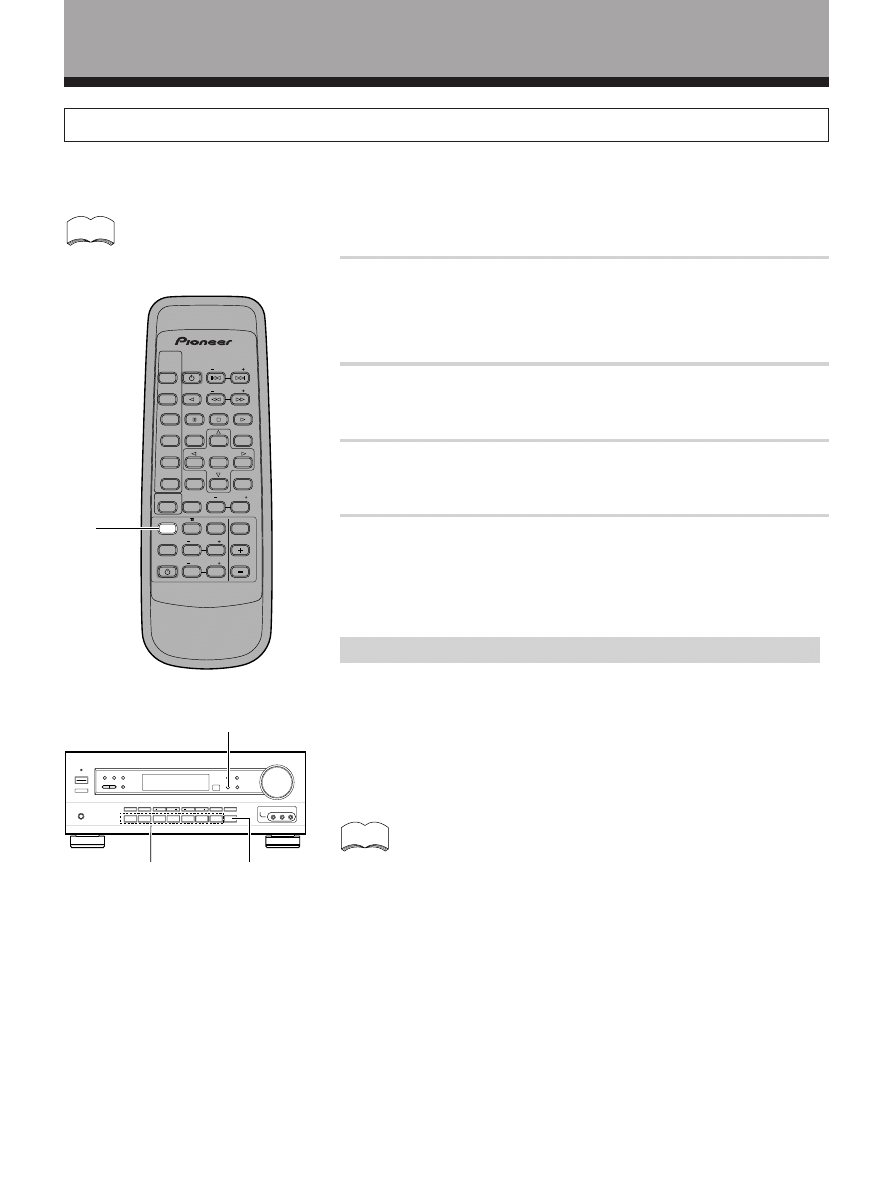
36
<ARB7192>
Recording from Audio Components
The following operations show you how to record audio to the cassette, DAT, or MD deck connected to the MD/TAPE 1
or TAPE 2 MONITOR jacks.
1
Select the component you want to record.
Be sure to press SIGNAL SELECT on the front panel to choose
“ANALOG”. (Refer to “Switching ANALOG/DIGITAL signal input” on
page 26.)
2
Prepare the program source.
(Tune in the radio station or load the CD, etc.)
3
Insert a blank tape into the cassette deck (MD/TAPE 1 or
TAPE 2 MONITOR) and adjust the recording level (if necessary).
4
Start recording on the cassette deck, then start playback
from the source component.
Record monitor (TAPE 2 MONITOR)
If you connect a cassette deck (etc.) with a record monitor function to the
TAPE 2 MONITOR jacks, you can listen to the sound of the recording as it is
being recorded.
Press TAPE 2 MONITOR to switch between the sound of the
recording (TAPE 2 indicator on) and the sound of the source
component (TAPE 2 indicator off).
1
TAPE 2
MONITOR
SIGNAL SELECT
The receiver’s volume, tone (BASS, TREBLE, and LOUDNESS), and surround effects have no effect on the
recorded signal.
memo
• This receiver outputs the input signal directly to the recording
device. As there is no conversion of the audio signal,
recordings cannot be made from analog to digital, and similarly
from digital to analog.
• The MD/TAPE 1 function is not able to record the TAPE 2
MONITOR.
memo
AV MULTI-CHANNEL RECEIVER
REMOTE CONTROL UNIT
RECEIVER
STANDBY/ON
LD
DVD
TUNER
MPX
STANDBY/ON
CLASS
D RECT
ACCESS
TAPE
TV FUNC
BAND
CD
SOURCE
SELECT
TEST TONE
EFFECT
SURROUND
DSP MODE
TV VOL
FREQ
0
9
5
1
3
MUTING
MASTER
VOLUME
Î
CD D SC
CHANNEL
STATION
TV
CONTROL
LEVEL
FUNCTION
CHANNEL
SELECT
ATT
6
2
4
7
1
Other Operations
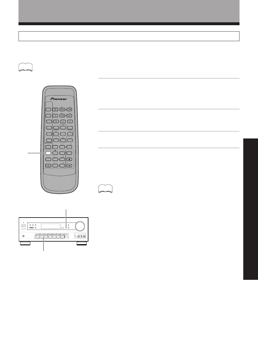
37
<ARB7192>
OPERA
TION
Other Operations
Recording from Video Components
The following operations show you how to record audio and video to the video tape recorder connected to the VCR
jacks.
1
Select the component you want to record.
Be sure to press SIGNAL SELECT on the front panel to choose
“ANALOG”. (Refer to “Switching ANALOG/DIGITAL signal input” on
page 26.)
2
Prepare the program source.
(Load the DVD or LD, etc.)
3
Insert a blank tape into the video tape recorder VCR.
4
Start recording on the video tape recorder, then start
playback from the source component.
memo
The receiver’s volume, tone (BASS, TREBLE, and LOUDNESS), and surround effects have no effect on the
recorded signal.
memo
• Recording cannot be made from analog to digital, and similarly
from digital to analog.
• When recording a DVD, the recorded image may flicker or be
difficult to view because of the copy protection signal
programmed on the DVD.
SIGNAL SELECT
1
AV MULTI-CHANNEL RECEIVER
REMOTE CONTROL UNIT
RECEIVER
STANDBY ON
LD
DVD
TUNER
MPX
TANDBY/ON
CLASS
DIRECT
ACCESS
TAPE
TV FUNC
BAND
CD
SOURCE
SELECT
TEST TONE
EFFECT
SURROUND
DSP MODE
TV VOL
FREQ
0
9
5
1
3
MUTING
MASTER
VOLUME
Î
CD DISC
CHANNEL
STATION
TV
CONTROL
LEVEL
FUNCTION
CHANNEL
SELECT
ATT
6
2
4
7
1
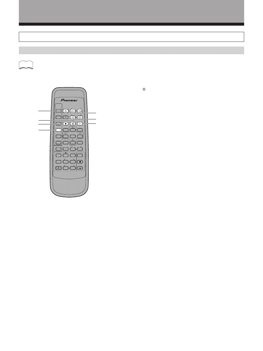
38
<ARB7192>
memo
Other Operations
Remote Controlling Other PIONEER Components
DVD player operations
Before to performing these operations, press the DVD (SOURCE SELECT) button to switch the remote to the
DVD operation mode.
AV MULTI-CHANNEL RECEIVER
REMOTE CONTROL UNIT
RECEIVER
STANDBY/ON
LD
DVD
TUNER
MPX
STANDBY/ON
CLASS
D RECT
ACCESS
TAPE
TV FUNC
BAND
CD
SOURCE
SELECT
TEST TONE
EFFECT
SURROUND
DSP MODE
TV VOL
FREQ
MUTING
MASTER
VOLUME
Î
CD DISC
CHANNEL
STATION
TV
CONTROL
LEVEL
FUNCTION
CHANNEL
SELECT
ATT
9
3
6
2
4
8
1
5
7
1
2
3
4
5
6
DVD
1
Press to switch the DVD player on or off.
2
7
Press to stop playback. (With certain models,
pressing this button when the unit is stopped may
open the disc tray.)
3
8
Press to pause playback. (With certain models, this
button may freeze the frame.)
4
4˜¢
4 : Press to return to the beginning of the current
chapter (track). Press repeatedly to return to the
beginning of previous chapters (tracks).
¢ : Press to advance to the beginning of the next
chapter (track). Press repeatedly to advance to the
beginning of following chapters (tracks).
5
1˜¡
1 : Hold down for fast reverse playback.
¡ : Hold down for fast forward playback.
6
3
Press to start playback.
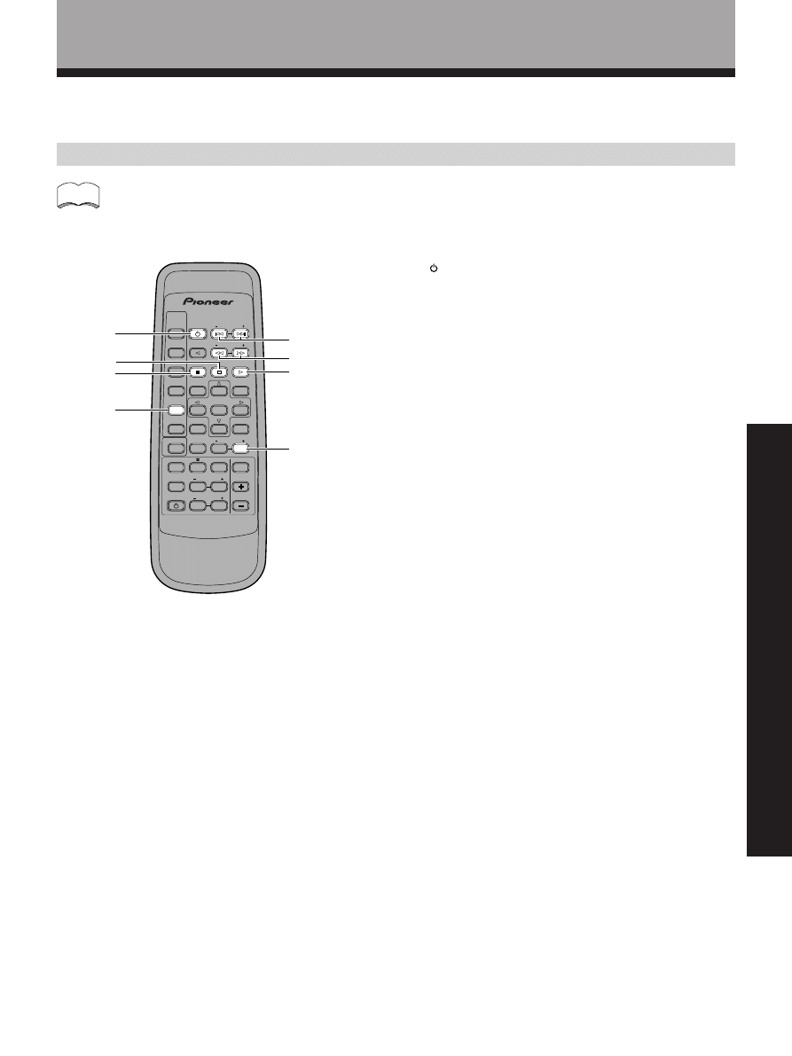
39
<ARB7192>
OPERA
TION
LD player operations
AV MULTI-CHANNEL RECEIVER
REMOTE CONTROL UNIT
RECEIVER
STANDBY/ON
LD
DVD
TUNER
MPX
STANDBY/ON
CLASS
D RECT
ACCESS
TAPE
TV FUNC
BAND
CD
SOURCE
SELECT
TEST TONE
EFFECT
SURROUND
DSP MODE
TV VOL
FREQ
MUTING
MASTER
VOLUME
Î
CD DISC
CHANNEL
STATION
TV
CONTROL
LEVEL
FUNCTION
CHANNEL
SELECT
ATT
9
3
6
2
4
8
1
5
7
1
2
3
4
5
6
7
Before to performing these operations, press the LD (SOURCE SELECT) button to switch the remote to the LD
operation mode.
Other Operations
memo
1
Press to switch the LD player on or off.
2
7
Press to stop playback. (With certain models,
pressing this button when the unit is stopped may
open the disc tray.)
3
8
Press to pause playback. (With certain models, this
button may set still pictures.)
4
4˜¢
4 : Press to return to the beginning of the current
chapter (track). Press repeatedly to return to the
beginning of previous chapters (tracks).
¢ : Press to advance to the beginning of the next
chapter (track). Press repeatedly to advance to the
beginning of following chapters (tracks).
5
1˜¡
1 : Hold down for fast reverse playback.
¡ : Hold down for fast forward playback.
6
3
Press to start playback.
7 CD DISC(+)
Switches between sides A and B of the disc.
LD
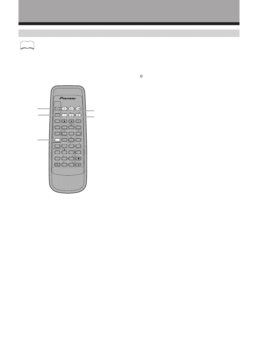
40
<ARB7192>
Other Operations
TV operations
Before to performing these operations, press TV CONTROL (SOURCE SELECT) to switch the remote to the TV
operation mode.
memo
1
Press to switch the TV on or off.
2 TV FUNC.
Press to switch the TV’s input (not possible with all
models). (This operation is possible regardless of the
current remote operation mode.)
3 CHANNEL (+/–)
Use to select a TV channel.
4 TV VOL. (+/–)
Use to adjust the volume of the TV.
AV MULTI-CHANNEL RECEIVER
REMOTE CONTROL UNIT
RECEIVER
STANDBY/ON
LD
DVD
TUNER
MPX
STANDBY/ON
CLASS
D RECT
ACCESS
TAPE
TV FUNC
BAND
CD
SOURCE
SELECT
TEST TONE
EFFECT
SURROUND
DSP MODE
TV VOL
FREQ
MUTING
MASTER
VOLUME
Î
CD DISC
CHANNEL
STATION
TV
CONTROL
LEVEL
FUNCTION
CHANNEL
SELECT
ATT
9
3
6
2
4
8
1
5
7
1
2
3
4
TV
CONTROL
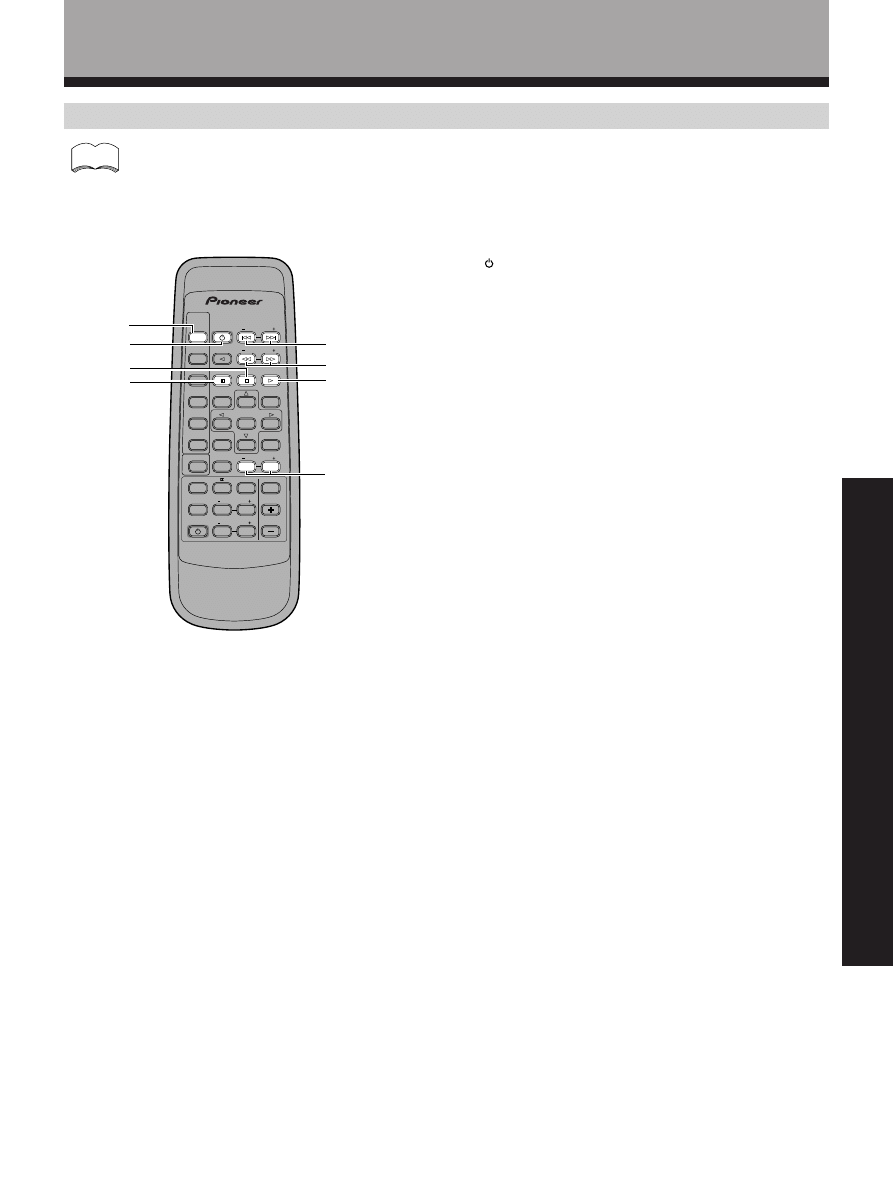
41
<ARB7192>
OPERA
TION
1
Press to switch the CD player on or off.
2
7
Press to stop playback.
3
8
Press to pause playback.
4
4˜¢
4 : Press to return to the beginning of the current
track. Press repeatedly to return to the beginning of
previous tracks.
¢ : Press to advance to the beginning of the next
track. Press repeatedly to advance to the beginning of
following tracks.
5
1˜¡
1 : Hold down for fast reverse playback.
¡ : Hold down for fast forward playback.
6
3
Press to start playback.
7 CD DISC(+/–)
For multi-disc CD changers, use to select the disc
numbers (not possible with all models).
CD player operations
Before to performing these operations, press the CD (SOURCE SELECT) button to switch the remote to the
CD operation mode.
memo
AV MULTI-CHANNEL RECEIVER
REMOTE CONTROL UNIT
RECE VER
STANDBY ON
LD
DVD
TUNER
MPX
STANDBY ON
CL
SS
DIRECT
ACCESS
TAPE
TV FUNC
BAND
CD
SOURCE
SELECT
TEST TONE
EFFECT
SURROUND
DSP MODE
TV VOL
FREQ
MUTING
MASTER
VOLUME
Î
CD DISC
CHANNEL
STATION
TV
CONTROL
LEVEL
FUNCTION
CHANNEL
SELECT
ATT
9
3
6
2
4
8
1
5
7
7
1
2
3
4
5
6
CD
Other Operations
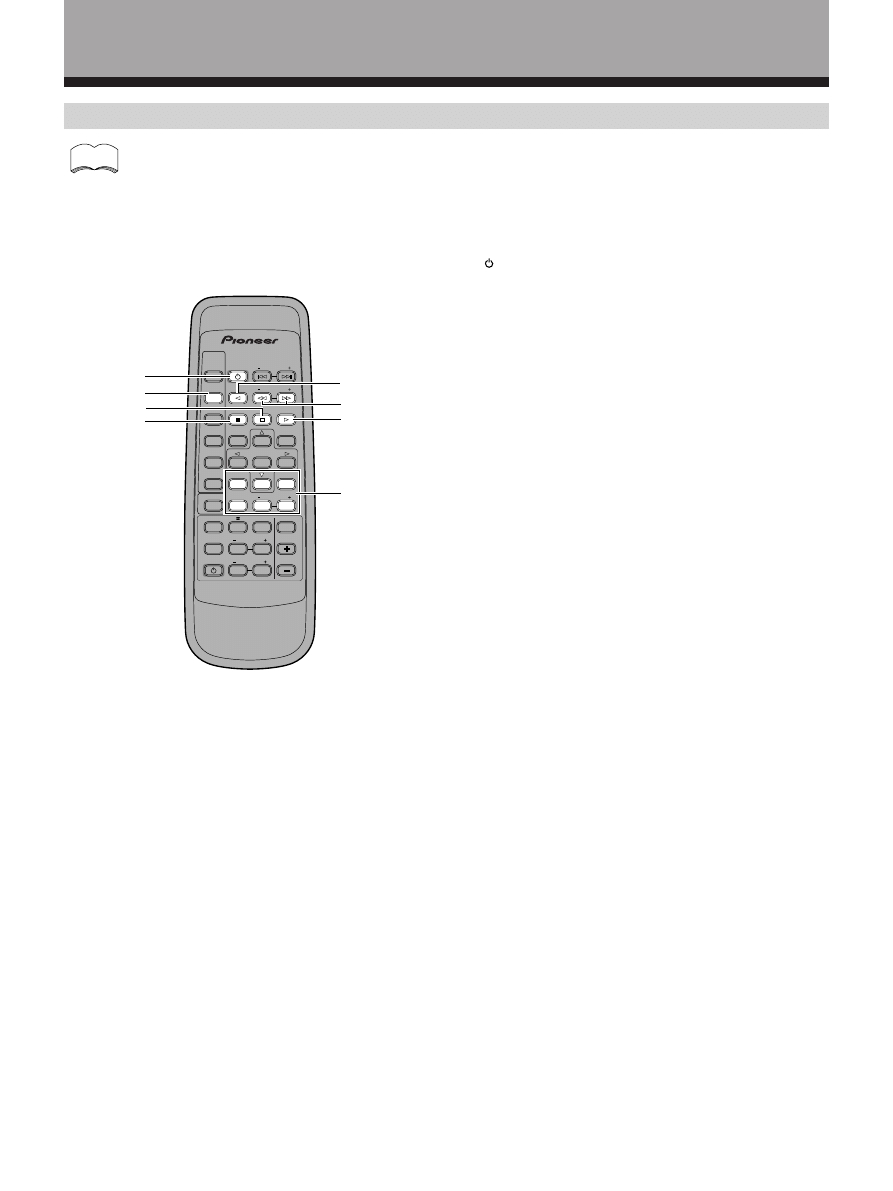
42
<ARB7192>
1
Press to switch the cassette deck on or off (not
possible with all models).
2
7
Press to stop playback or recording.
3
8
Press to pause playback or recording.
4
2
Plays in the direction of the arrow.
5
1˜¡
1 : Press to rewind the tape. Hold down during
playback for fast reverse playback (not possible with
all models).
¡ : Press to fast forward the tape. Hold down during
playback for fast forward playback (not possible with
all models).
6
3
Press to start playback.
7 Number buttons
Use to operate deck 1 of a double cassette deck (not
possible with all cassette decks).
7 button (
2)
Plays in the direction of the arrow.
8 button (
1)
Press to rewind the tape. Hold down during playback
for fast reverse playback (not possible with all
models).
9 button (
¡)
Press to fast forward the tape. Hold down during
playback for fast forward playback.
0 button (
8)
Press to fast forward the tape. Hold down during
playback for fast forward playback.
CD DISC + (
3)
Press to start playback.
CD DISC – (
7)
Press to stop playback or recording.
Cassette deck operations
Before to performing these operations, press the TAPE (SOURCE SELECT) button to switch the remote to the
TAPE operation mode.
Other Operations
memo
AV MULTI-CHANNEL RECEIVER
REMOTE CONTROL UNIT
RECEIVER
STANDBY/ON
LD
DVD
TUNER
MPX
STANDBY/ON
CLASS
D RECT
ACCESS
TAPE
TV FUNC
BAND
CD
SOURCE
SELECT
TEST TONE
EFFECT
SURROUND
DSP MODE
TV VOL
FREQ
MUTING
MASTER
VOLUME
Î
CD DISC
CHANNEL
STATION
TV
CONTROL
LEVEL
FUNCTION
CHANNEL
SELECT
ATT
0
9
3
6
2
4
8
1
5
7
1
3
4
5
6
7
2
TAPE
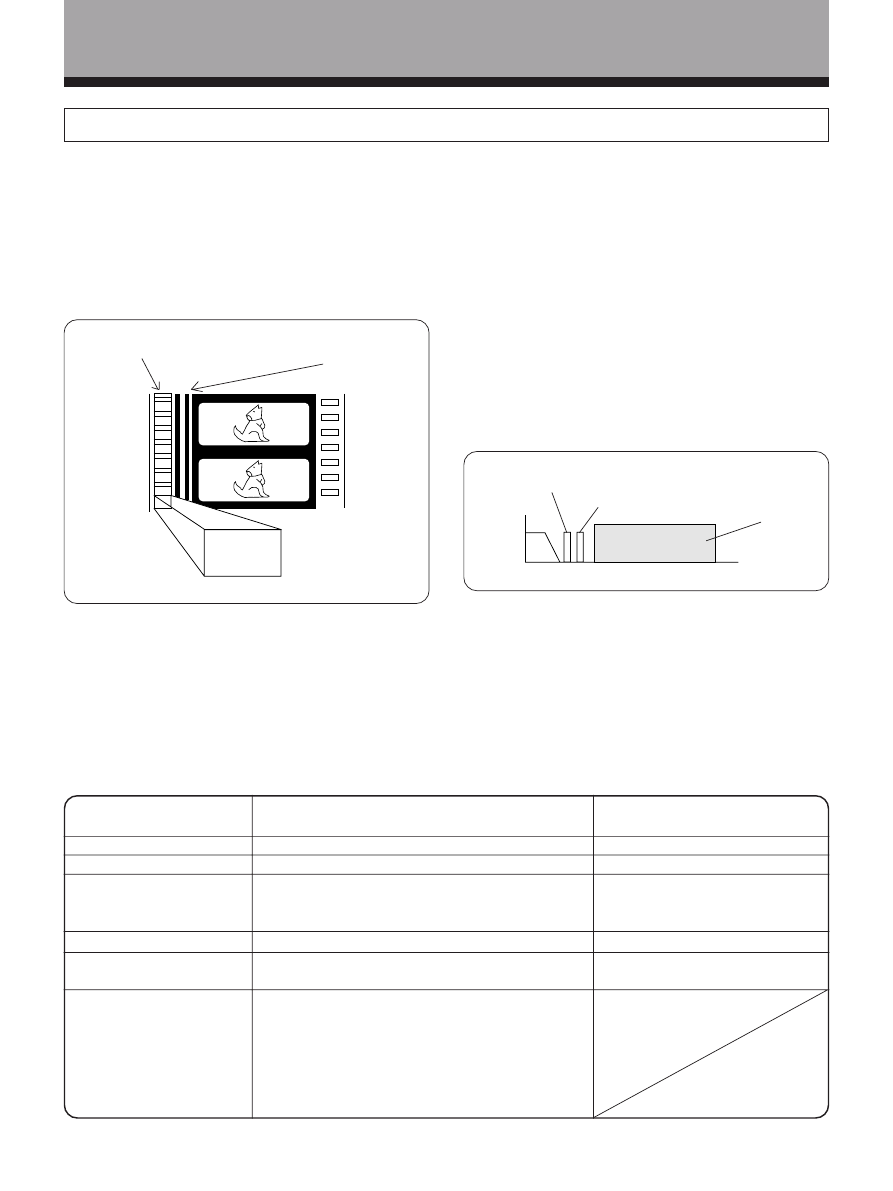
43
<ARB7192>
No. of recorded channels
No. of playback channels
Playback channel structure
Sound processing
Rear (Surround) high
frequency playback limit
Other
Dolby Digital
5.1 channels (Max.)
5.1 channels (Max.)
Front Left, Front Right, Center, Surround Left,
Surround Right, Sub Woofer
Digital discrete processing
20,000 Hz
• 5.1 completely independent channels
• High dynamic range
• Stable position, high phase characteristics, and
advanced surround effects reproduction
• High efficiency
(Compression rate of about one-tenth)
Dolby Pro Logic Surround
2 channels
4 channels
Front Left, Front Right, Center,
Surround
Analog matrix processing
7,000 Hz
Additional Information
Dolby Digital
Dolby Digital is a compression format which records the
sound of 6 channels of the theater surround system
(Dolby Digital) on the movie film digital track. Of the 6
channels, the sub woofer channel is intended for bass
only, and because the frequency range is smaller than
the main channel, it is expressed as 5.1 channel.
Dolby Digital is the name of the Dolby surround multi-
channel digital system that was developed after the
Dolby Surround System and Dolby Pro Logic Surround
System.
The number of movies made using Dolby Digital since
1992 has exceeded 300 and continues to increase. For
compact disc players and laser disc digital sounds, 16
bits are used to sample the original analog audio
waveform and sampling is carried out 44,100 times every
second. However because an enormous amount of
recording signal data is required for the multi channel
system with this method, AC-3 is used to compress the
data.
In reproducing audio signals, the smaller the bit number
used, the lower the sound quality. With AC-3, drop in
auditory sound quality is prevented by using masking
technology and digital filtering technology based on the
human auditory characteristics.
Laser disc format
Laser discs are now available on the market in large
numbers. This means that the recording of different
format audio signals on the laser disc raises the
important question of compatibility with existing laser
discs. Dolby Digital tracks on Laser Discs record signals
using the space of one analog audio channel so it will
maintain compatibility with existing discs and players.
As shown in the following figure, the digital audio
sounds of Dolby Digital discs can be played back as
currently done. Analog sounds are played back by using
the other channel without the Dolby Digital signals for
monaural audio signals.
5.1 channel digital
surround track
4 channel analog
sound track (Matrix)
AC-3
encoding
AC-3 for motion picture
Digital
sound
2
4
6
8
10
12
14 MHz
Frequency
Analog sound
(Monaural)
Video
Dolby Digital
sound
(Monaural)
Comparison with Dolby Pro Logic Surround
Dolby Digital is also known as the 5.1 channel system. It
is equipped with 5 channels (front left, front right, center,
surround left, surround right) in the frequency range
from 20 Hz to 20 kHz and an independent Low Frequency
Effect (LEF) channel. The sub woofer channel is also
called Low Frequency Effect (LFE).
The subwoofer channel can be used as desired to enjoy
strong bass sounds.
The following table shows the comparison with Dolby
Pro Logic Surround effects.

44
<ARB7192>
Additional Information
Troubleshooting
Incorrect operations are often mistaken for trouble and malfunctions. If you think that there is something wrong with
this component, check the points below. Sometimes the trouble may lie in another component. Investigate the other
components and electrical appliances being used. If the trouble cannot be rectified even after exercising the checks
listed below, ask your nearest PIONEER authorized service center or your dealer to carry out repair work.
Cause
• The power plug is disconnected.
• The protection circuit may have
been activated.
• Static electricity caused by dry air.
• Improper connections.
• Sound is muted.
• The volume is turned down.
• The TAPE 2 MONITOR is ON.
• Speakers are turned OFF.
• Improper connections.
• The input source is not properly
selected.
• Incorrect frequency.
• The antenna is not connected.
• AC-3 RF and/or digital cables are
near the antenna terminals and
wires.
FM broadcasts
• The FM antenna is not fully
extended or is poorly positioned.
• Weak radio signals.
AM broadcasts
• The AM antenna is poorly
positioned.
• Weak radio signals.
• Interference cause by other
equipment (fluorescent lamp,
motor, etc.).
Symptom
The power does not turn ON.
The unit does not respond when the
buttons are pressed.
No sound is output when a function
is selected.
No image is output when a function
is selected.
Considerable noise in radio
broadcasts.
Remedy
• Connect the power plug to the wall
outlet.
• Disconnect the power plug from
the outlet, and insert again.
• Disconnect the power plug from
the outlet, and insert again.
• Make sure the component is
connected correctly (refer to pages
9 to 13).
• Press MUTING on the remote
control.
• Adjust MASTER VOLUME.
• Press the TAPE 2 MONITOR button.
• Press SPEAKERS (A/B) to select the
speakers you connected.
• Make sure the component is
connected correctly (refer to pages
10, 11).
• Press the correct function button.
• Tune in the correct frequency.
• Connect the antenna (refer to page 8).
• Route AC-3 RF and digital cables
away from the antenna terminals
and wires.
• Fully extend the FM wire antenna,
position for best reception, and
secure to a wall.
• Connect an outdoor FM antenna
(refer to page 8).
• Adjust the direction and position
for best reception.
• Connect an additional internal or
external AM antenna (refer to page 8).
• Turn off the equipment causing the
noise or move it away from the
receiver.
• Place the antenna farther away
from the equipment causing the
noise.
45
<ARB7192>
Additional Information
Symptom
Broadcast stations cannot be selected
automatically.
No sound from surround or center
speakers.
Sound is produced from other
components, but not from LD or DVD
player.
Cannot be remote controlled.
The display is dark.
Cause
• Weak radio signals.
• Speaker settings are incorrect.
• The rear and/or center levels are
turned down.
• The surround and/or center
speakers are disconnected.
• SIGNAL SELECT is set incorrectly.
• The digital inputs are assigned
incorrectly, or not at all.
• The remote control batteries have
worn out.
• Too far away or bad angle of
operation.
• There is an obstacle between the
receiver and the remote control.
• Strong light such as fluorescent
light is shining onto the unit's
remote control signal light-
receiving window.
• A cord is connected to the
CONTROL IN terminal on this unit.
• This is not a malfunction.
Remedy
• Connect an outdoor antenna (refer
to page 8).
• Refer to “SPEAKER setting mode”
on page 16 to check the speaker
settings.
• Refer to “Adjusting the speaker
volume” on page 20 to check the
speaker levels.
• Connect the speakers (refer to
page 13).
• Set SIGNAL SELECT to "DIGITAL" or
"ANAROG" according to the type of
connections made. (refer to page 26)
• Set the digital input setting
correctly (refer to page 15, 19).
• Replace the batteries (refer to page 6).
• Operate within 23 feet (7 m), 30° of
the remote sensor on the front
panel (refer to page 7).
• Remove the obstacle or operate
from another position.
• Avoid exposing the remote sensor
on the front panel to direct light.
• Connect cord to the correct jack.
• In standby, pressing STANDBY/
ON while holding down the
button (both on the front panel)
returns the display to the default
brightness.
If the unit does not operate normally due to external effects such as static electricity
Disconnect the power plug from the outlet and insert again to return to normal operating conditions.

46
<ARB7192>
Additional Information
Amplifier Section
Continuous average power output of 80
watts* per channel, min., at 8 ohms, from 20
Hz to 20,000 Hz with no more than 0.09 %**
total harmonic distortion (front).
Continuous Power Output
Front ...................................... 80 W + 80 W (1 kHz, 0.8 %, 8
Ω)
Center ................................................. 80 W (1 kHz, 0.8 %, 8
Ω)
Rear ....................................... 80 W + 80 W (1 kHz, 0.8 %, 8
Ω)
Input (Sensitivity/Impedance)
VCR, DVD/LD, TV/SAT, VIDEO, CD, MD/TAPE1, TAPE 2
........................................................................ 200 mV/47 k
Ω
Frequency Response
VCR, DVD/LD, TV/SAT, VIDEO, CD, MD/TAPE1, TAPE 2
....................................................... 5 Hz to 100,000 Hz dB
Output (Level/Impedance)
VCR REC, MD/TAPE1 REC, TAPE 2 REC .......... 200 mV/2.2 k
Ω
Tone Control
BASS ................................................................. ± 6 dB (100 Hz)
TREBLE .............................................................. ± 6 dB (10 kHz)
LOUDNESS ................................. +9 dB/+7 dB (100 Hz/10 kHz)
Signal-to-Noise Ratio (IHF, short circuited, A network)
VCR, DVD/LD, TV/SAT, VIDEO, CD, MD/TAPE1, TAPE 2
..................................................................................... 97 dB
Signal-to-Noise Ratio [EIA, at 1 W (1 kHz)]
VCR, DVD/LD, TV/SAT, VIDEO, CD, MD/TAPE1, TAPE 2
..................................................................................... 80 dB
*
Measured pursuant to the Federal Trade Commission’s Trade
Regulation rule on Power Output Claims for Amplifiers.
** Measured by Audio Spectrum Analyzer.
VIDEO Section
Input (Sensitivity/Impedance)
VCR, DVD/LD, TV/SAT, VIDEO ............................... 1 Vp-p/75
Ω
Output (Level/Impedance)
VCR, MONITOR ...................................................... 1 Vp-p/75
Ω
Frequency Response
VCR, MONITOR .......................................... 5 Hz to 7 MHz dB
Signal-to-Noise Ratio .......................................................... 55 dB
Cross Talk ............................................................................. 55 dB
FM Tuner Section
Frequency Range ...................................... 87.5 MHz to 108 MHz
Usable Sensitivity ................. Mono: 13.2 dBf, IHF (1.3 µV/75
Ω)
50 dB Quieting Sensitivity .................................. Mono: 20.2 dBf
Stereo: 38.6 dBf
Signal-to-Noise Ratio ............................ Mono: 73 dB (at 85 dBf)
Stereo: 70 dB (at 85 dBf)
Specifications
Specifications
+0
–3
+0
–3
Distortion .................................................... Stereo: 0.5 % (1 kHz)
Alternate Channel Selectivity ............................. 60 dB (400 kHz)
Stereo Separation ................................................... 40 dB (1 kHz)
Frequency Response ............................. 30 Hz to 15 kHz (± 1) dB
Antenna Input ................................................... 75
Ω unbalanced
AM Tuner Section
Frequency Range ........................................ 530 kHz to 1,700 kHz
Sensitivity (IHF, Loop antenna) .................................... 350 µV/m
Selectivity ............................................................................ 25 dB
Signal-to-Noise Ratio .......................................................... 50 dB
Antenna ................................................................... Loop antenna
Miscellaneous
Power Requirements .......................................... AC 120 V, 60 Hz
Power Consumption ............................................. 280 W, 400 VA
Power Consumption in Standby mode ............................. 2.5 W
AC Outlet
SWITCHED ............................................... 100 W (0.8 A) MAX
Dimensions ....................................................................................
420 (W)
× 158 (H) × 391 (D) mm
16-9/16 (W)
× 6-1/4 (H) × 15-3/8 (D) in
Weight (without package) .............................. 9.8 kg (21 lb 10 oz)
Furnished Parts
FM Antenna ................................................................................. 1
AM Loop Antenna ....................................................................... 1
Dry Cell Batteries (SIZE “AA” (IEC R6P)) ................................... 2
Remote Control Unit ................................................................... 1
Operating Instructions ................................................................ 1
NOTE:
Specifications and the design are subject to possible modifications
without notice, due to improvements.

47
<ARB7192>
Please do not ship your product to Pioneer without first calling the Customer Service Department at
the above listed number for assistance.
8 0 0 – 4 2 1 – 1 4 0 4
For warranty information please see the Limited Warranty sheet included with your product.
PIONEER ELECTRONICS SERVICE, INC.
CUSTOMER SERVICE DEPARTMENT
P.O. BOX 1760, LONG BEACH,
CA 90801-1760, U.S.A.
Should this product require service in the U.S.A. and you wish to locate the nearest Pioneer
Authorized Independent Service Company, or if you wish to purchase replacement parts, operating
instructions, service manuals, or accessories, please call the number shown below.
We
Want You
LISTENING
For A Lifetime
Selecting fine audio equipment such as the unit you’ve just purchased
is only the start of your musical enjoyment. Now it’s time to consider how
you can maximize the fun and excitement your equipment offers. This
manufacturer and the Electronic Industries Association’s Consumer
Electronics Group want you to get the most out of your equipment by
playing it at a safe level. One that lets the sound come through loud and
clear without annoying blaring or distortion-and, most importantly, without
affecting your sensitive hearing.
Sound can be deceiving. Over time your hearing “comfort level” adapts
to higher volumes of sound. So what sounds “normal” can actually be loud
and harmful to your hearing. Guard against this by setting your equipment
at a safe level BEFORE your hearing adapts.
To establish a safe level:
• Start your volume control at a low setting.
• Slowly increase the sound until you can hear it comfortably and clearly,
and without distortion.
Once you have established a comfortable sound level:
• Set the dial and leave it there.
Taking a minute to do this now will help to prevent hearing damage or
loss in the future. After all, we want you listening for a lifetime.
We Want You Listening For A Lifetime
Used wisely, your new sound equipment will provide a lifetime of fun
and enjoyment. Since hearing damage from loud noise is often undetectable
until it is too late, this manufacturer and the Electronic Industries
Association’s Consumer Electronics Group recommend you avoid
prolonged exposure to excessive noise. This list of sound levels is included
for your protection.
Decibel
Level
Example
30
Quiet library, soft whispers
40
Living room, refrigerator, bedroom away from traffic
50
Light traffic, normal conversation, quiet office
60
Air conditioner at 20 feet, sewing machine
70
Vacuum cleaner, hair dryer, noisy restaurant
80
Average city traffic, garbage disposals, alarm clock
at two feet.
THE FOLLOWING NOISES CAN BE DANGEROUS UNDER
CONSTANT EXPOSURE
90
Subway, motorcycle, truck traffic, lawn mower
100
Garbage truck, chain saw, pneumatic drill
120
Rock band concert in front of speakers, thunderclap
140
Gunshot blast, jet plane
180
Rocket launching pad
Information courtesy of the Deafness Research Foundation.
We
Want You
LISTENING
For A Lifetime
For Assistance With Basic Set-up, Operation, or Trouble
Shooting, You May Contact Our Customer Service
Hotline at 1(800)421-1404(USA ONLY)
Power cord CAUTION!
Handle the power cord by the plug. Do not pull out the
plug by tugging the cord and never touch the power cord
when your hands are wet as this could cause a short
circuit or electric shock. Do not place the unit, a piece of
furniture, etc., on the power cord, or pinch the cord.
Never make a knot in the cord or tie it with other cords.
The power cords should be routed such that they are not
likely to be stepped on. A damaged power cord can
cause a fire or give you an electrical shock. Check the
power cord once in a while. When you find it damaged,
ask your nearest PIONEER authorized service center or
your dealer for a replacement.
Maintenance of External Surfaces
• Use a polishing cloth or dry cloth to wipe off dust
and dirt.
• When the surfaces are dirty, wipe with a soft cloth
dipped in some neutral cleanser diluted five or six
times with water, and wrung out well, and then wipe
again with a dry cloth. Do not use furniture wax or
cleaners.
• Never use thinners, benzine, insecticide sprays or
other chemicals on or near this unit, since these will
corrode the surfaces.
E S T 1 9 2 4
EIA
E
L
E
C
T
R
O
N I
C
I ND
U
S
T
R
IE
S
•
A
S
S O
C I A T
I O
N
•
E S T 1 9 2 4
EIA
E
L
E
C
T
R
O
N I
C
I ND
U
S
T
R
IE
S
•
A
S
S O
C I A T
I O
N
•
Published by Pioneer Electronic Corporation.
Copyright © 1999 Pioneer Electronic Corporation.
All rights reserved.
PIONEER ELECTRONIC CORPORATION
4-1, Meguro 1-Chome, Meguro-ku, Tokyo 153-8654, Japan
PIONEER ELECTRONICS [USA] INC.
P.O. BOX 1540, Long Beach, California 90801-1540
PIONEER ELECTRONICS OF CANADA, INC.
300 Allstate Parkway, Markham, Ontario L3R OP2, Canada
PIONEER ELECTRONIC [EUROPE] N.V.
Haven 1087, Keetberglaan 1, 9120 Melsele, Belgium TEL: 03/570.05.11
PIONEER ELECTRONICS AUSTRALIA PTY. LTD.
178-184 Boundary Road, Braeside, Victoria 3195, Australia, TEL: 03-9586-6300
PIONEER ELECTRONICS DE MEXICO S.A. DE C.V.
San Lorenzo Num 1009 3er piso Desp. 302 Col. Del Valle, Mexico D.F. C.P. 03100 TEL: 5-688-52-90
<99B00ZZ0J00> Printed in <ARB7192-A>
Wyszukiwarka
Podobne podstrony:
Pioneer VSX D309 Owners Manual
Pioneer VSX 405 Service Manual
Pioneer CS 53 Owners Manual
Pioneer BDP 208DBK Owners Manual
Pioneer SA 6300 Owners Manual
Pioneer BDP 101A Owners Manual
Pioneer BR 95C Owners Manual
Pioneer VSX 21 Service Manual
Pioneer AVIC X710BT Owners Manual
Pioneer AVIC Z1 Owners Manual
Pioneer CDJ 500S Owners Manual
Pioneer SA 1005 Owners Manual
Pioneer TX 5500II Owners Manual
Pioneer CDX P680 Owners Manual
Pioneer SX 7730 Owners Manual
Pioneer BDC 2202 Owners Manual
Pioneer BR 95 Owners Manual
Pioneer SA 970 Owners Manual
Pioneer TX 710 L Owners Manual
więcej podobnych podstron