
Initial Print Date: 05/09
Table of Contents
Subject
Page
M Chassis and Suspension
Revision Date:

Table of Contents
Subject
Page

Table of Contents
Subject
Page
BLANK
PAGE

4
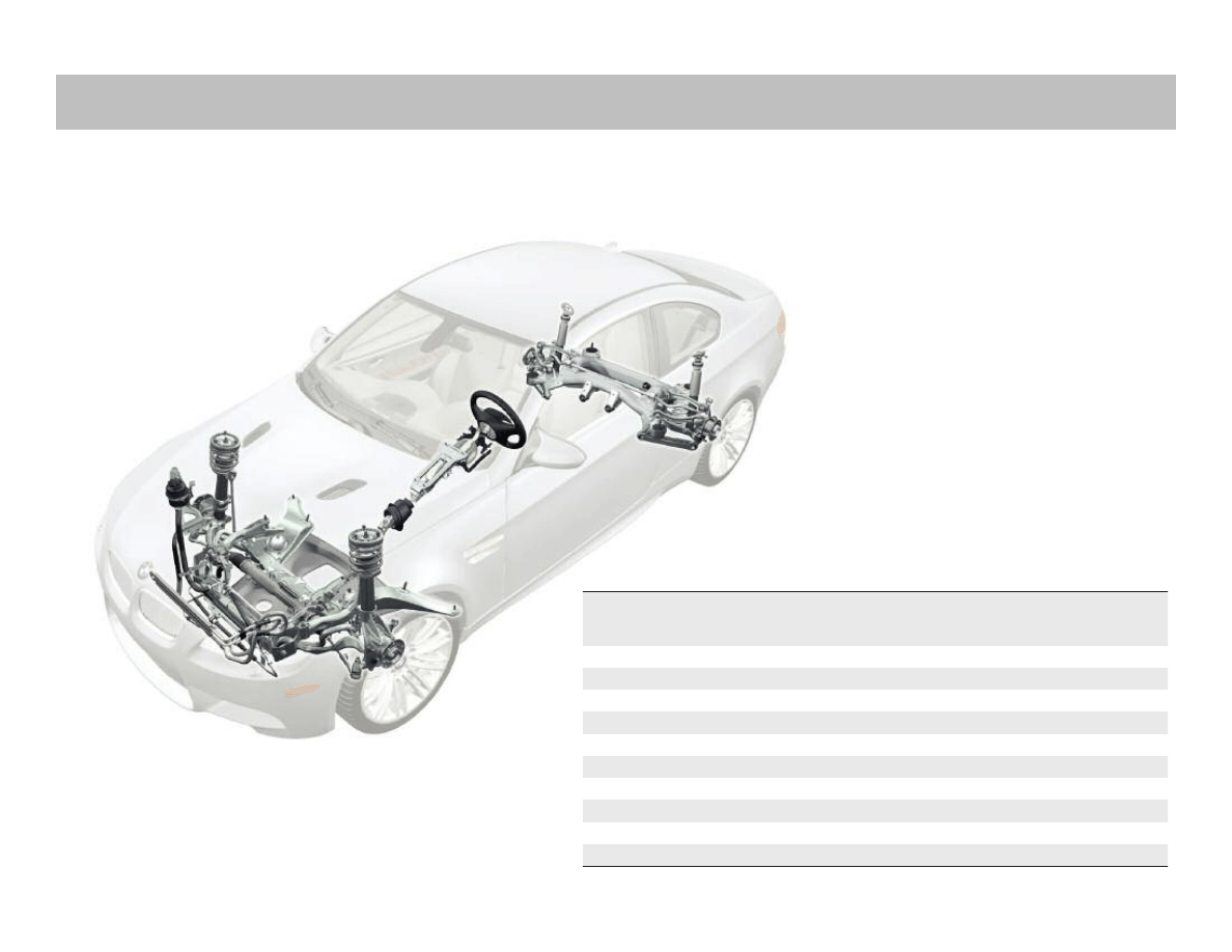
M Chassis and Suspension
M Chassis and Suspension
Model: E60 M5, E63/64 M6 and E9x M models
Production: From Start of Production
After completion of this module you will be able to:
• Identify the changes made to the suspensions of the M5, M6 and M3 when compared
to the series production vehicles.
• Explain the components used in the steering system of the M5, M6 and M3.
• Identify the version of DSC used in the different M models.
• Identify the braking system upgrades made to the M vehicles when compared
to series production vehicles.
M Chassis and Suspension
5
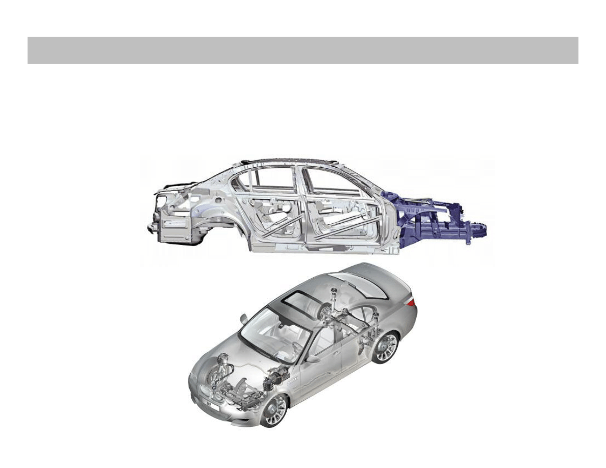
Body
The E60 M5 utilizes the same body construction as the produc-
tion based 5 Series E60. The main body is made of steel and the
front end utilizes the familiar GRAV technology.
GRAV or "gewichtsreduzierter aluminiumvorderbau“ is a light-
weight aluminum front end which enhances the lightweight
design of the vehicle. Almost the entire front end is made of
aluminum.
The transition to steel in the composite construction starts in the
vicinity of the engine bulkhead. The reduced weight of the front
end in particular contributes much to the ideal axle-load distribu-
tion of 50:50.
E60 M5
6
M Chassis and Suspension
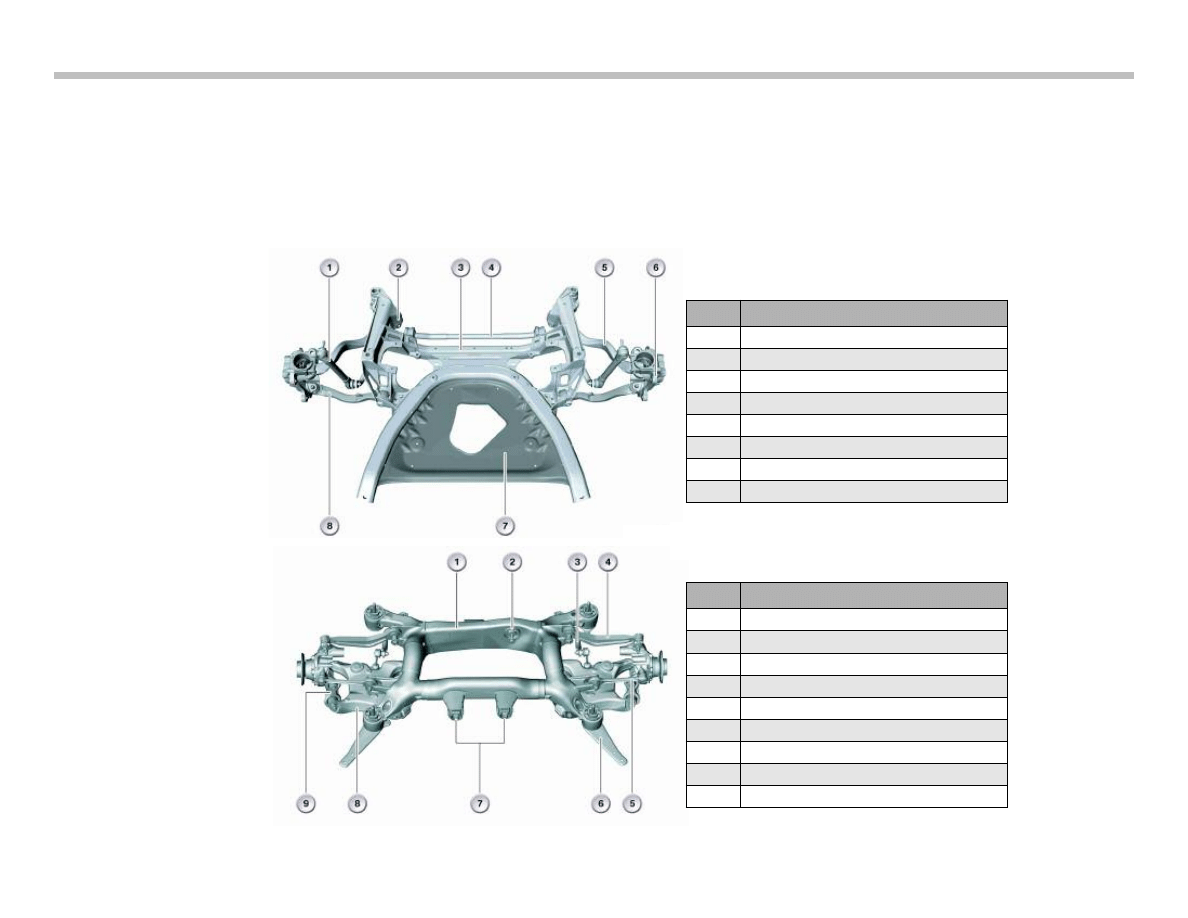
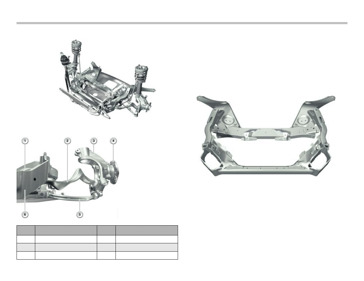
Suspension Components
The control arms and transverse links are made of aluminum and
ensure high-precision tracking of the wheels. The highly innovative
design principle with the special layout of the leading links and
control arms ensures high-precision steering. The low axle loads,
especially in the area of the front axle, also provide for a high
degree of agility and familiar BMW handling characteristics.
Index
Explanation
1
Stabilizer Link
2
Hydro-Mount
3
Front Axle Carrier
4
Stabilizer Bar (No ARS)
5
Tension Strut
6
Swivel Bearing
7
Reinforcement Plate
8
Control Arm
Index
Explanation
1
Axle Carrier
2
Differential Bearing, rear
3
Stabilizer Bar
4
Control Arm
5
Traction Strut
6
Thrust Rod
7
Differential Bearing, front
8
Swinging Arm
9
Integral Link
Front Axle
Rear Axle
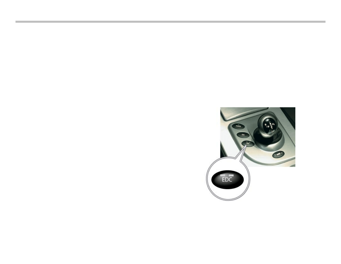
EDC-K
The continuously variable electronic damping control (EDC-K)
system used in the E65/66 is used in the E60 M5.
The continuous Electronic Damping Control (EDC-K) absorbs
vertical forces while driving and dampens these forces to the
chassis.
The forces are measured by two vertical acceleration sensors on
the front axle (left and right) and one at the rear axle (right). The
front sensors are located in the wheel housings and the rear on the
trunk tray underneath the trunk ventilation ports. The dampening
characteristics are mapped in the control module to continuously
regulate the EDC-K providing maximum comfort.
The EDC-K works with infinitely variable valves in the dampers to
regulate the hydraulic fluid flow using electromagnetic control
valves. EDC-K provides the actual damping force required at any
time.
The steering angle sensor is used along with the front wheel speed
sensors to determine the lateral acceleration.
The controller provides the opportunity to select from three basic
settings:
“Comfort” - Comfort-oriented coordination of shock absorbers
and steering
“Normal“ - Offers a balanced mixture of the comfort and the
sports program
“Sport” - Consistently sporty coordination of shock absorbers
and steering.
Selecting Program
To select between the three programs available, press the EDC
button repeatedly:
"Comfort": No LED lights up in the button.
"Normal": One LED lights up in the button.
"Sport": Both LEDs light up in the button.
The last selected program is active each time the engine is started.
You can also activate your preferred program with the button on the
steering wheel.
Note: For further information regarding vehicle settings
refer to the Performance Controls section of this
training material or the Vehicle Owner’s Manual.
M Chassis and Suspension
7
Brakes
The M5 has braking distances equal to top sports car levels.
The new BMW M5 owes its enormous braking power to double
piston aluminum brake calipers and perforated, ventilated com-
pound (floating) brake rotors.
The braking distance for the M5 is approximately 118ft from
62 mph to a full stop.
The front rotors measurements are 374 x 36 mm.
The rear rotors measure 370 x 24 mm.
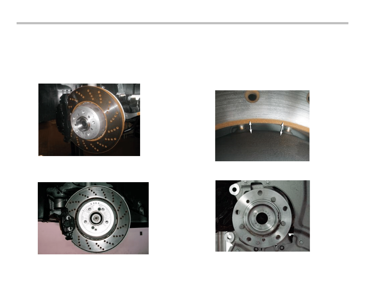
Rotors
Both the front and rear rotors are cross drilled floating type. These
ensure optimized heat dissipation, improved response, as well as
reduction of unsprung masses.
The rotor has an aluminum center section (hub) with pins embed-
ded in a radial pattern that are “connected” to the rotor surface uti-
lizing a free moving or floating configuration. This allows the rotor
surface to contract and expand with the changes in temperature.
8
M Chassis and Suspension
Front rotor of E60 M5
Rear rotor of E60 M5
Detail of Rotor Attachment Pins
Detail of Rotor Alignment Pins on Hub
The rotor is attached to the hub with two allen style screws and
three alignment pins located on the hub.
The rotor outer ring is cast and holes are drilled out to improve
braking. The drilled surface allows gases that form between the
brake pad and rotor to escape. Otherwise, there would be a thin
film of “brake gases” between the surface of the rotor and the
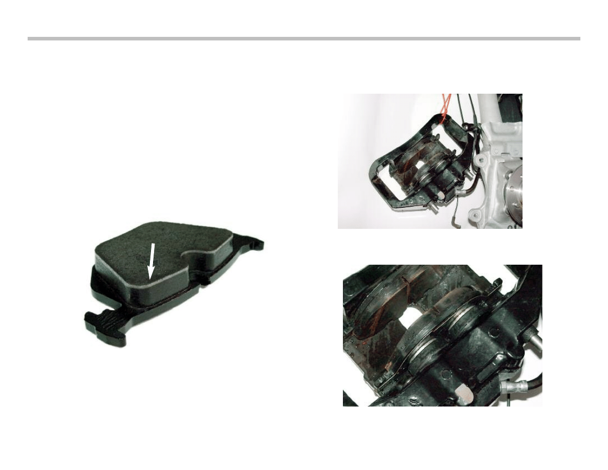
brake pads.
Brake pads are made by gluing the friction material to a backing
plate (metal). These are then baked in an oven to allow the glue
to cure. While the brakes are heated, gasses are released and
travel through the brake pads to the surface. This can be seen on
any new brake pads as a lighter upper section of the brake pad (see
picture below).
Calipers
The M5 utilizes dual piston brake calipers in the front and conven-
tional single piston calipers in the rear.
M Chassis and Suspension
9
Dual Piston Front Brake Caliper
Dual Piston Front Brake Caliper (close-up view)
Rear Brake Pads (“gasses”)
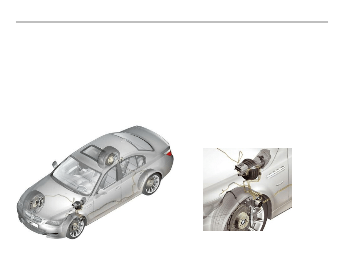
Dynamic Stability Control (DSC)
The E60 M5 is equipped with the Continental Teves Dynamic
Stability Control System (DSC+) MK60E5. Although all E6x vehi-
cles where updated to the Bosch traction control and stability sys-
tem DSC8+ from 09/2005, the M5 still uses the Teves system.
The MK60E5 system is also used in the E9x M3. The system is a
further development of the MK60psi system. The abbreviation
"psi" stands for "pressure sensor integrated" i.e. the two pressure
sensors of the tandem master brake cylinder (THZ) have been
combined to form one plausibility sensor and integrated in the
hydraulic unit.
The designation "E5" in MK60E5 signifies the 5 pressure sensors
that are integrated in the hydraulic unit: One pressure sensor that
measures the pressure from the tandem master brake cylinder THZ
and four further sensors that measure the braking pressure of the
respective wheel brake.
This system offers functions that were not yet available with the
previous system.
MK60E5 added the following functions:
• Brake Readiness
• Dry Braking
• Hill Ascent Assistant
The features of this system distinctly enhance comfort during
control intervention while facilitating even more precise individual
wheel braking in connection with the analog control valves.
This system made it possible to reduce the required braking dis-
tance compared to previous systems. The E60 M5 has a braking
distance of less than 118 feet from a speed of 62 mph (< 36 m
from 100 km/h).
10
M Chassis and Suspension
Mounting Location of DSC Control Unit and Hydraulic Unit

Compared to the standard DSC features, the MK60E5 in the E60
M5 has been upgraded by the following additional functions:
• MDynamic Mode (MDM is activated via the M-Drive)
• Brake readiness (Brake Standby)
• Dry braking
• Hill ascent assistant
The following functions are not used on the M5:
• Performance control (FLR)
• Soft stop
• Fading brake support (FBS)
• Dynamic traction control (DTC)
Operating Modes of the MK60E5
In principle, the MK60E5 has 3 different operating modes:
• DSC ON
• DSC OFF
• MDynamic mode
There is no DTC function in connection with the M5. However,
similar to DTC mode, corresponding control thresholds are raised
by activating the MDM.
MDynamic Mode (MDM)
MDM gives the performance-oriented driver the option of driving
the car with controlled float angle and longitudinal slip without DSC
intervening. The control system intervenes only when the physical
limits are exceeded. MDM is activated via the M-Drive.
The control thresholds are not static but rather, as the speed
increases, they approach the thresholds of DSC ON mode.
The stability control thresholds are identical as from a speed of
approximately 125 mph (200 km/h) in order not to overtax the driver
in the high speed range.
Hill Ascent Assistant
Assistance is provided when driving off on uphill gradients by
briefly maintaining a specific brake pressure in the wheel brakes.
This function is active only when the transmission is not in "N"
position and the handbrake is released.
DSC ON/OFF has no influence in this case.
The tilt angle (uphill and downhill gradient) is calculated from the
measured value of the longitudinal acceleration sensor. The DSC
calculates the necessary holding pressure based on the uphill or
downhill gradient.
After releasing the brake pedal, the braking pressure is immediately
decreased to the calculated holding pressure which is then
reduced in stages after a maximum time delay of 0.7 seconds. The
vehicle will start off after approximately 1 seconds if the driver does
not press the accelerator pedal.
The longitudinal acceleration sensor is assigned to the SMG
system. The DSC control unit receives this signal over the bus net-
work.
Note: This function is also active on an incline with reverse
gear engaged
Condition Based Service (CBS)
The MK60E5 calculates and evaluates the condition of the brake
pads. In contrast to the E60 Series, the M5 is equipped with two
brake pad sensors on the front axle.
M Chassis and Suspension
11
12
M Chassis and Suspension
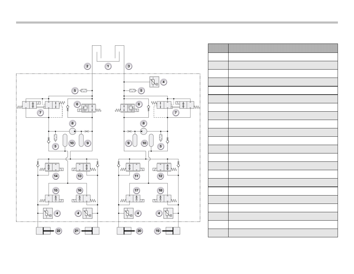
Index
Explanation
1
Brake Fluid Reservoir
2
Rear Axle
3
Front Axle (hydraulic connection)
4
Pressure Sensor, push rod circuit
5
Pulsation Damper
6
Isolating Valve
7
Electric Changeover Valve
8
Self-Priming Return Pump
9
Damper Chamber
10
Accumulator Chamber
11
Front Left Inlet Valve with Orifice Plate, analog
12
Front Right Inlet Valve with Orifice Plate, analog
13
Rear Right Inlet Valve, analog
14
Rear Left Inlet Valve, analog
15
Rear Left Outlet Valve
16
Rear Right Outlet Valve
17
Front Left Outlet Valve
18
Front Right Outlet Valve
19
Front Right Wheel Brake
20
Front Left Wheel Brake
21
Rear Right Wheel Brake
22
Rear Left Wheel Brake
DSC MK60E Hydraulics Diagram
System Components
The predominant differences in the design of MK60E5 compared
to MK60psi are:
• Analog valves
• 4 pressure sensors for individual braking pressure acquisition
at each wheel.
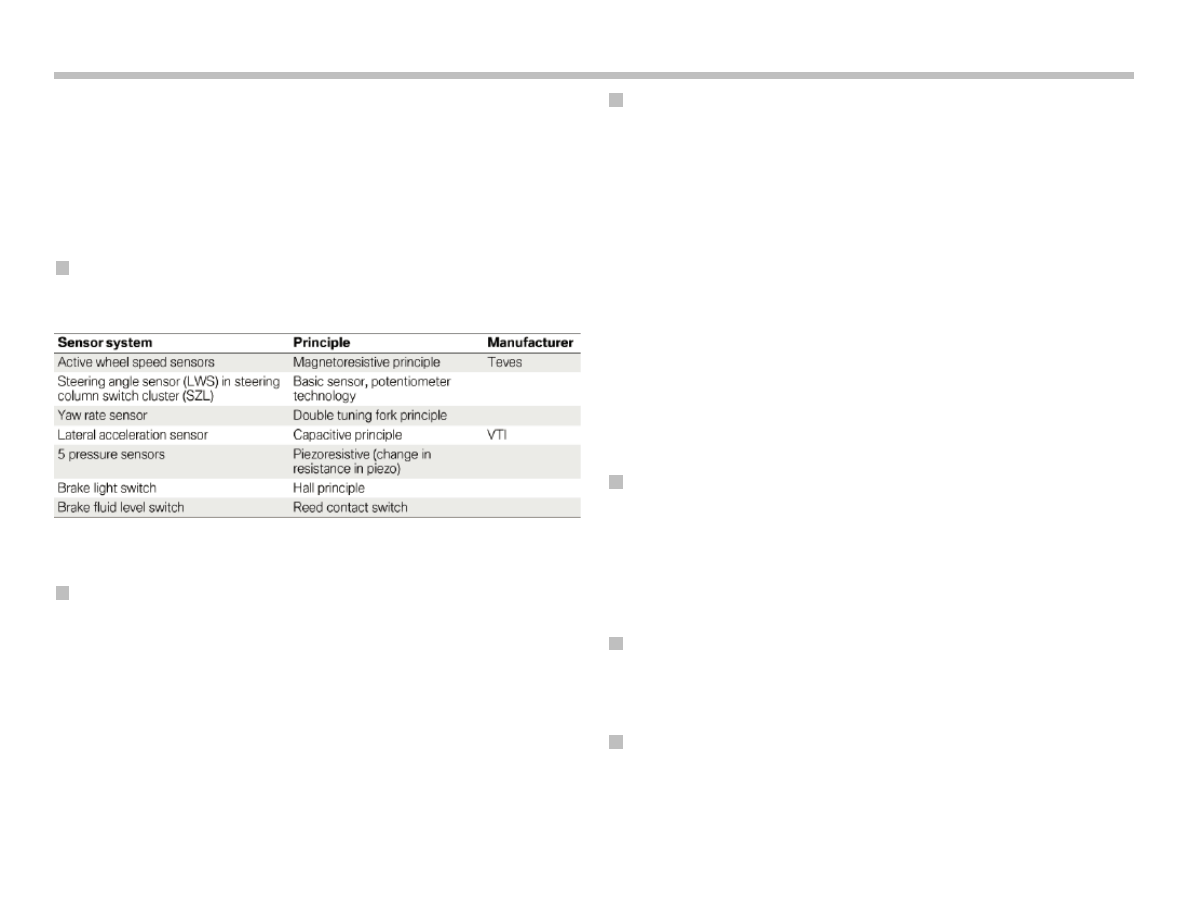
Sensors
Control Unit
The control unit is mounted behind the left front wheel well cover
and is attached to the hydraulic unit. It consists of:
• Add-on control unit
• Integrated semiconductor relay (motor and valve relay).
Hydraulic Unit
The Teves MK60E5 hydraulic unit consists of:
• Front axle
– 2 analog inlet valves
– 2 high-speed outlet valves
– 1 isolating valve
– 1 changeover valve
• Rear axle
– 2 analog inlet valves
– 2 high-speed outlet valves
– 1 isolating valve
– 1 changeover valve
Pressure Generation
• Pump with two differential piston pump elements
• Operated by means of common eccentric shaft
• 250 W pump motor
• ASC and DSC mode: Self-priming return pump
Engine Intervention
• Ignition timing adjustment
• Charge control
Interfaces
• CAN-bus interface (F-CAN, PT-CAN)
M Chassis and Suspension
13
14
M Chassis and Suspension
The chassis of the E9X M3 is based on the chassis of the E9X
series models respectively. All modifications are described in this
section.
E90 M3
Designation
E92 M3
Series E92 335i
Tire type/Wheel rim type/Rim
offset [mm]
245-40 ZR 18/8.5Jx18/
IS29
225-45 WR 17 RSC/8Jx17/
IS34
5
9
2
5
0
3
Tire radius [mm]
Wheelbase [mm]
2761
2760
0
0
5
1
8
3
5
1
]
m
m
[
h
t
d
i
w
k
c
a
r
T
Total toe
16’
14’
Toe differential angle
2° 14’
1° 40’
Camber
-1°
-18’
Kingpin inclination
15°
4
1
’
2
° 7’
Kingpin offset [mm]
8.4
5.1
3
.
0
2
4
.
9
2
]
m
m
[
li
a
r
T
Trail angle
7° 8’
7° 5’
E92 M3 Chassis
M Chassis and Suspension
15
Double-jointed Spring Strut Front Axle
Front Axle Carrier
The front axle carrier is an aluminum alloy construction. In order to
ensure optimum strength and torsional rigidity, a high-pressure
forming technique has been used to manufacture certain sections.
Aluminum has been chosen for its lightweight and strength proper-
ties. The components of the front axle are joined together by an
aluminum welding process.
Index
Explanation
Index
Explanation
1
Rubber mount for tension strut
4
Wheel hub
2
Tension strut
5
Wishbone
3
Swivel bearing
6
Front axle carrier
Front axle carrier
Complete front axle
Wheel suspension components
16
M Chassis and Suspension
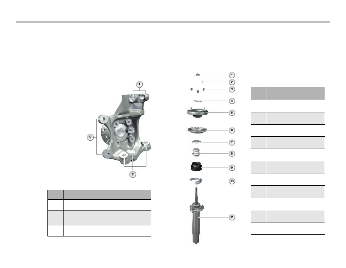
Swivel Bearing
The ’M’ swivel bearing is completely new. The bearing is made
from an aluminum cast alloy, which reduces the weight by 500
grams.
The following changes have been made to the front wheel carrier:
• Adjusted dimensions for the larger 'M' wheel.
• As described below, the
method by which the
spring strut is clamped
into the swivel bearing
has been changed.
• The geometric fixing
points for the wishbone,
tension strut and steering
track rod have been
selected to ensure opti-
mum sports vehicle kine-
matics.
• Modified mounting posi-
tion for the larger brake
caliper.
Spring Strut
The front steel suspension spring has a 95 mm compression and
100 mm rebound travel.
A new spring concept supports lateral chassis stability. Depending
on the vehicle weight (equipment), modified spring types are used.
Index
Explanation
1
Clamp connection of the spring strut support
2
Attachment points for the tension strut,
wishbone and steering track rod
3
Brake caliper mounting
Index
Explanation
1
Retaining nut, shock absorber
to support bearing
2
Dowel pin, support bearing to
body
3
Mounting fixture, support bearing
to body
4
Joint seat
5
Support bearing
6
Upper spring seat
7
Support disc
8
Additional damper/spring
9
Gaiter
10
Lower spring seat
11
Spring strut
M Chassis and Suspension
17
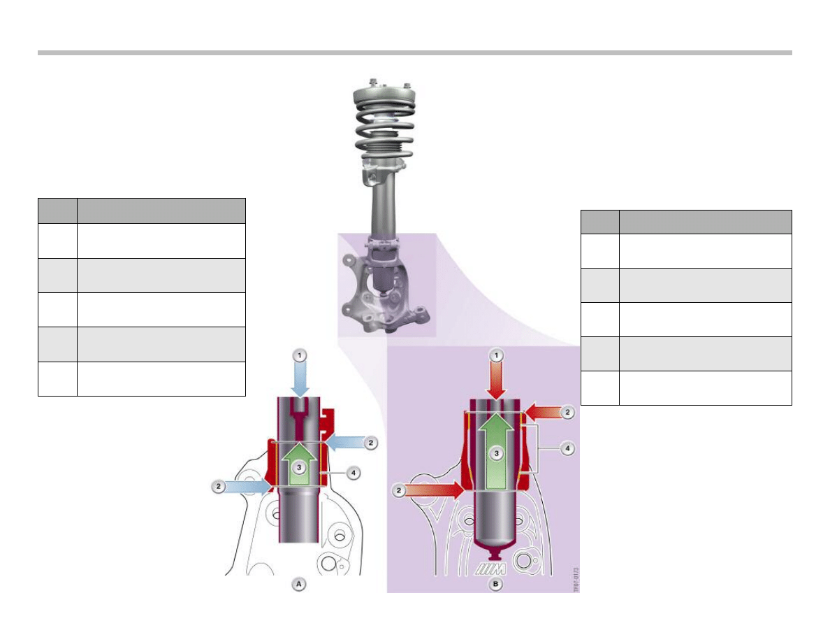
Index
Explanation
A
Spring strut support in the
E9x series model
1
Vertical force (Z-axis)
2
Upper and lower limit for supporting lat-
eral and longitudinal force (X and Y axis)
3
Clamp height 52 mm parallel fit
4
Parallel contact face
Index
Explanation
B
Spring strut support in the E9x M3
1
Vertical force (Z-axis)
2
Upper and lower limit for supporting lat-
eral and longitudinal force (X and Y axis)
3
Clamp height 76 mm with parallel
upper and conical lower fit
4
Upper cylindrical and lower
conical contact face
Spring strut connection to the wheel carrier
compared to the E9x series models
18
M Chassis and Suspension
As shown in the diagram, the clamp height has been increased on
the Z-axis from 52 mm on the E9x series model (left) to 76 mm on
the E9x M3 (right).
The front spring strut now has an additional support. The wheel
carrier has also been modified to compensate for the increased
drive and dynamic forces.
The lower contact face of the spring strut in the E9x M3 has a
cone, which is positioned firmly in the wheel carrier. In E9x vehi-
cles, however, the front spring strut has a parallel construction and
is only held in place by the clamping force.
This design change and the increased clamp height accommodate
the increased reaction forces of the spring strut and increase the
overall stability of the wheel suspension.
During assembly, the M3 spring strut is pulled into the lower cone
using a new special tool.
Note: Follow the installation and removal process accord-
ing to the service repair instructions.
Tension Strut
The tension strut is similar to that used in the E9x series vehicles,
but features an 'M'-specific harder rubber mount.
Wishbone
The M control arm is completely new and is connected to the axle
carrier and wheel carrier by two ball joints. It is manufactured out of
forged aluminum alloy.
Wheel Bearing Unit
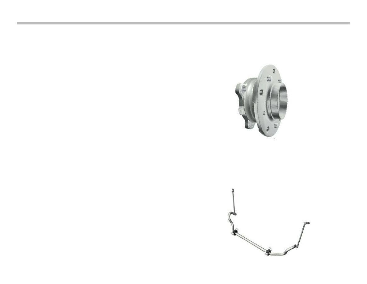
The M3 wheel bearing unit is identical to the E60 M5 wheel bear-
ing unit. It has three dowel pins for the brake disc.
Front Anti-roll Bar
The weight-optimized front anti-roll bar was adapted for the M3
and has a special rubber bearing material for more direct response.
The hinged brackets are made out of an aluminum alloy (steel in
E9x series vehicles).
M Chassis and Suspension
19
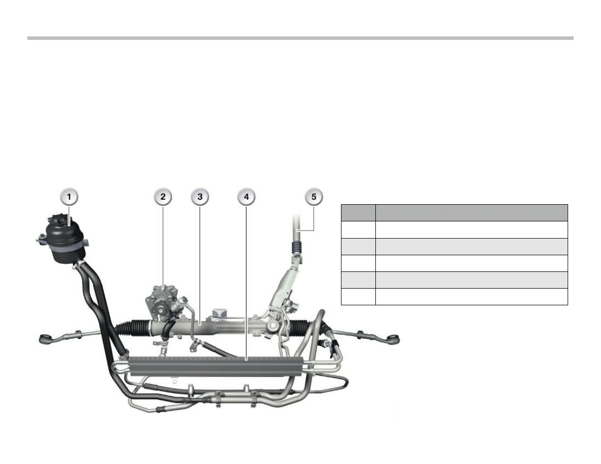
Steering System
The design of the rack-and-pinion steering system is the same as
in the E9x series vehicles. The average variable overall ratio is 12.5
(sports-oriented comared to16 in the E9x series).
In the M3, the steering force support is controlled by the MSS60
via the Servotronic valve. A speed dependent characteristic curve
is stored in the MSS60 for this purpose. With the MDrive menu
option, a second and even more sports oriented characteristic
curve can be activated (see the chapter on MDrive).
The steering oil is guided through the steering oil cooler before it
returns to the oil reservoir.
The E9x M3 is not available with active steering.
Index
Explanation
1
Steering oil header tank
2
Steering oil hydraulic pump
3
Steering transmission housing
4
Steering oil cooler
5
Steering wheel spindle
20
M Chassis and Suspension
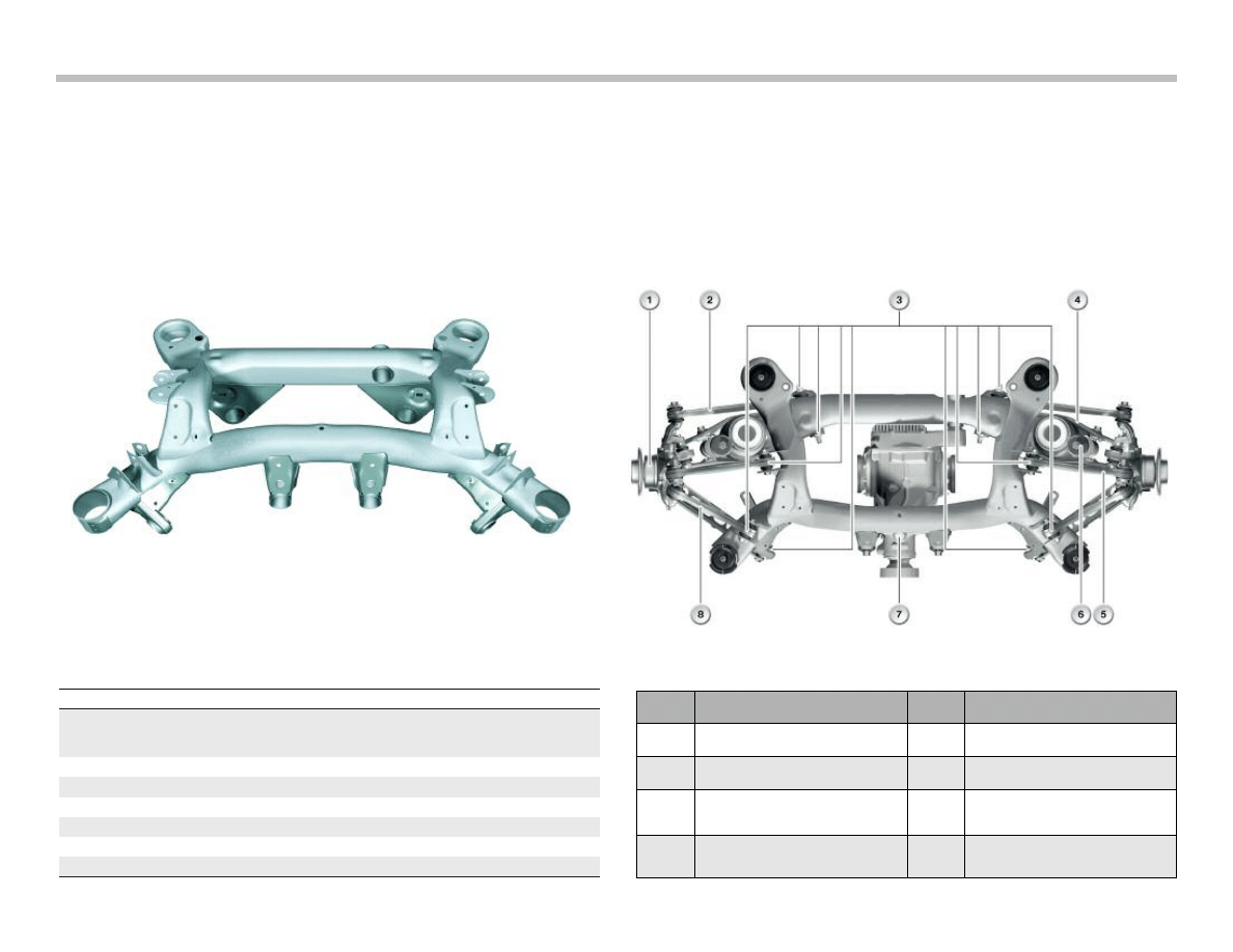
Rear Axle
The rear axle carrier is constructed from steel sections which are
welded together. All mounting points for the rear axle and suspen-
sion components are formed or attached to the axle carrier making
it an integral component.
Nearly all components of the rear chassis have been revised, the
aim is to achieve optimum sports vehicle kinematics, chassis stabil-
ity and a more precise and direct response, with a simultaneous
reduction in weight.
This has been achieved by the careful selection of materials for the
axle components and bearings, and through a modification of the
axle geometry.
Designation
E92 M3
Series E92 335i
Tire type/Wheel rim type/Rim
offset [mm]
265-40 ZR 18/9.5Jx18 /
IS23
225-45 WR 17 RSC/8Jx17/
IS34
5
9
2
1
1
3
Tire radius [mm]
Wheelbase [mm]
2761
2760
3
1
5
1
9
3
5
1
]
m
m
[
h
t
d
i
w
k
c
a
r
T
Total toe
10’
18’
Driving axis angle
0°
0°
Camber
-1° 45’
-1° 30’
Index
Explanation
Index
Explanation
1
Wheel carrier
5
Wishbone
2
Toe struts
6
Shock absorber
3
Connections from control arm to
rear axle carrier
7
Rear axle carrier
4
Camber struts
8
Traction strut with semi-trailing
arm below it
Construction of Rear Axle
M Chassis and Suspension
21
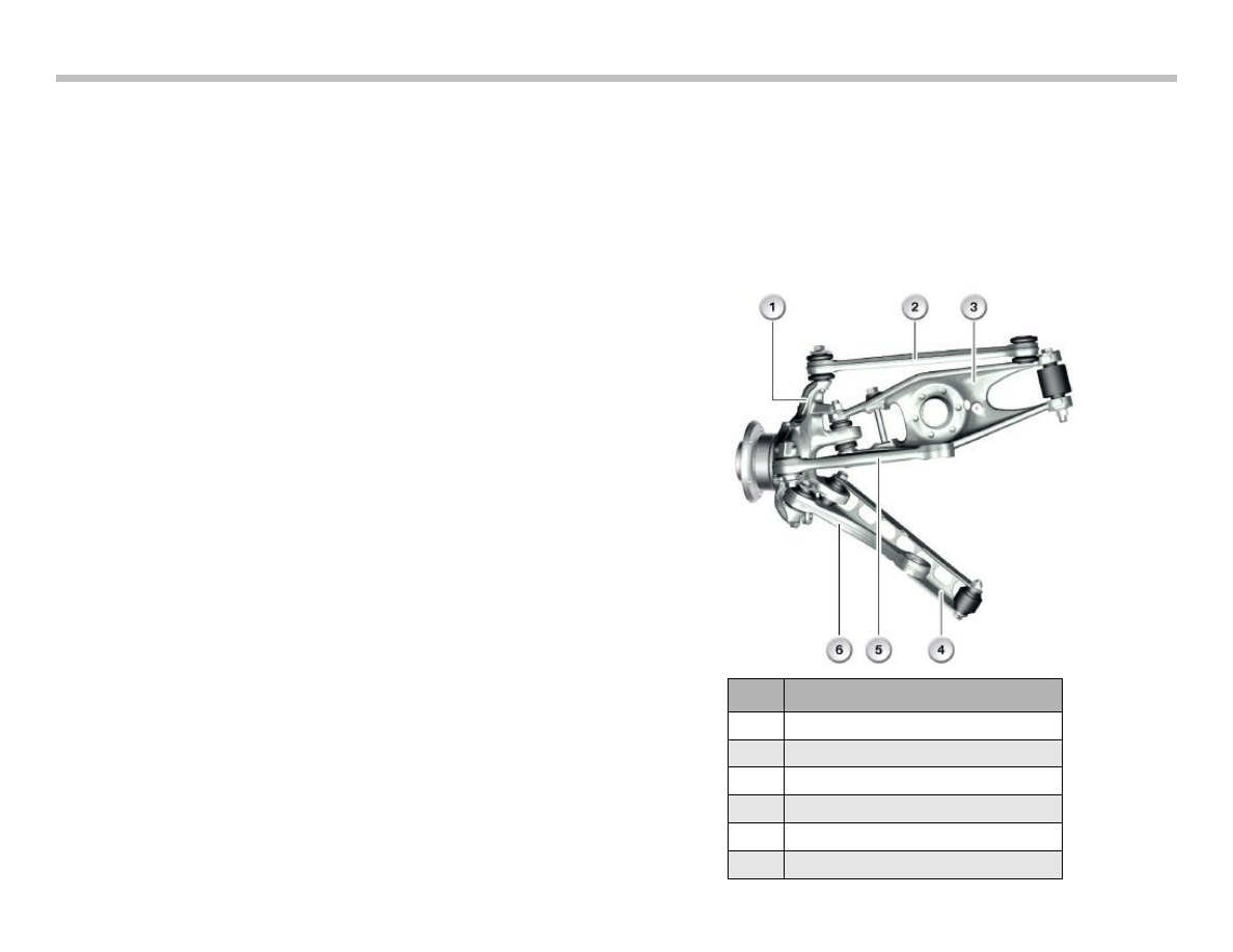
Wheel Carrier
The attachment points for toe, camber, wishbone, longitudinal and
traction struts have been positioned specifically for the 'M' model.
Its overall dimensions allow for the larger M wheel to be fitted. The
’M’ wheel carrier is fitted with a modified rubber mount connecting
to the semi-trailing arm and a ball joint for the camber strut.
Toe Struts
The new ’M’ toe strut is forged from Aluminum. It is one-piece and
has two integrated ball joints.
Camber Struts
The 'M' camber strut is a new lightweight component forged from
Aluminum. Its design reduces the unsprung mass of the vehicle.
Wishbone
The new 'M' wishbone is forged from aluminum and has a modi-
fied integrated ball joint and a rubber mount.
Control Strut
The semi-trailing arm is the only rear suspension strut that is taken
from the E9x vehicles. It is connected further inwards on the rear
axle carrier, only the rubber mount is new.
Traction Strut
The geometry of the forged aluminum 'M' traction strut has been
revised. It now has a new integrated rubber mount for the wheel
carrier. The ball joint for the rear axle carrier has been taken from
the E9x series vehicles .
Rear Shock Absorbers
New 'M' specific rear aluminum dampers are fitted to the M3.
Electronic damper control - continuous (EDC-K), is available as an
option.
The integrated lower damper rubber mount has a support sleeve
that improves the rigidity and stability between the damper and the
camber strut.
Index
Explanation
1
Wheel carrier
2
Toe strut
3
Camber strut
4
Control strut
5
Wishbone
6
Traction strut
Overview of rear axle struts
22
M Chassis and Suspension
Electronic Damper Control - Continuous (EDC-K)
EDC-K is available for the first time in the E9x M3. EDC-K is an
option and is based on the EDC-K in the E65 and E60 M5.
Both dampers of one axis are always activated in parallel. The valve
is installed internally in the damper in the damper oil system.
The compression phase, and in particular the rebound phase, of
the shock absorbers can be adjusted by the EDC-K depending on
the input signals in a smooth transition from relatively comfortable
to a harder sports setting.
The driver can choose between three settings, the controlled pro-
grams "Comfort" and "Normal", or the uncontrolled fixed setting
"Sport".
The program is selected using the EDC-K button on the center
console or preset via the MDrive menu and activated using the M
button on the steering wheel (for more information, see the MDrive
chapter).
The input signals come from two vertical acceleration sensors in
the front wheel arches and a third sensor in the rear right-hand
wheel arch.
The steering column switch cluster sends the steering angle to the
F-CAN. This is transmitted together with the wheel speeds from
the DSC to the PT-CAN and evaluated in the EDC-K control unit.
The longitudinal, lateral and vertical accelerations calculated as a
result are used as a basis for regulation.
The EDC-K button signal enters the junction box and is transmitted
to the EDC-K on the PT-CAN.
M Chassis and Suspension
23
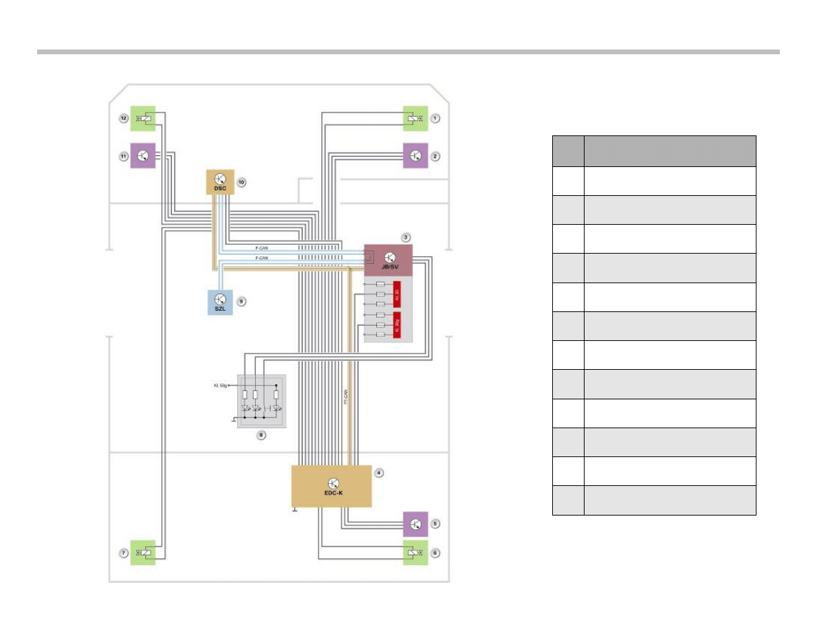
EDC-K System Circuit Diagram
Index
Explanation
1
EDC valve, front right
2
Vertical acceleration sensor, front right
3
Junction box/distribution box
4
EDC-K control unit
5
Vertical acceleration sensor, rear left
6
EDC valve, rear right
7
EDC valve, rear left
8
EDC button on center console
9
Steering column switch cluster
10
DSC control unit
11
Vertical acceleration sensor, front left
12
EDC valve, front left
24
M Chassis and Suspension
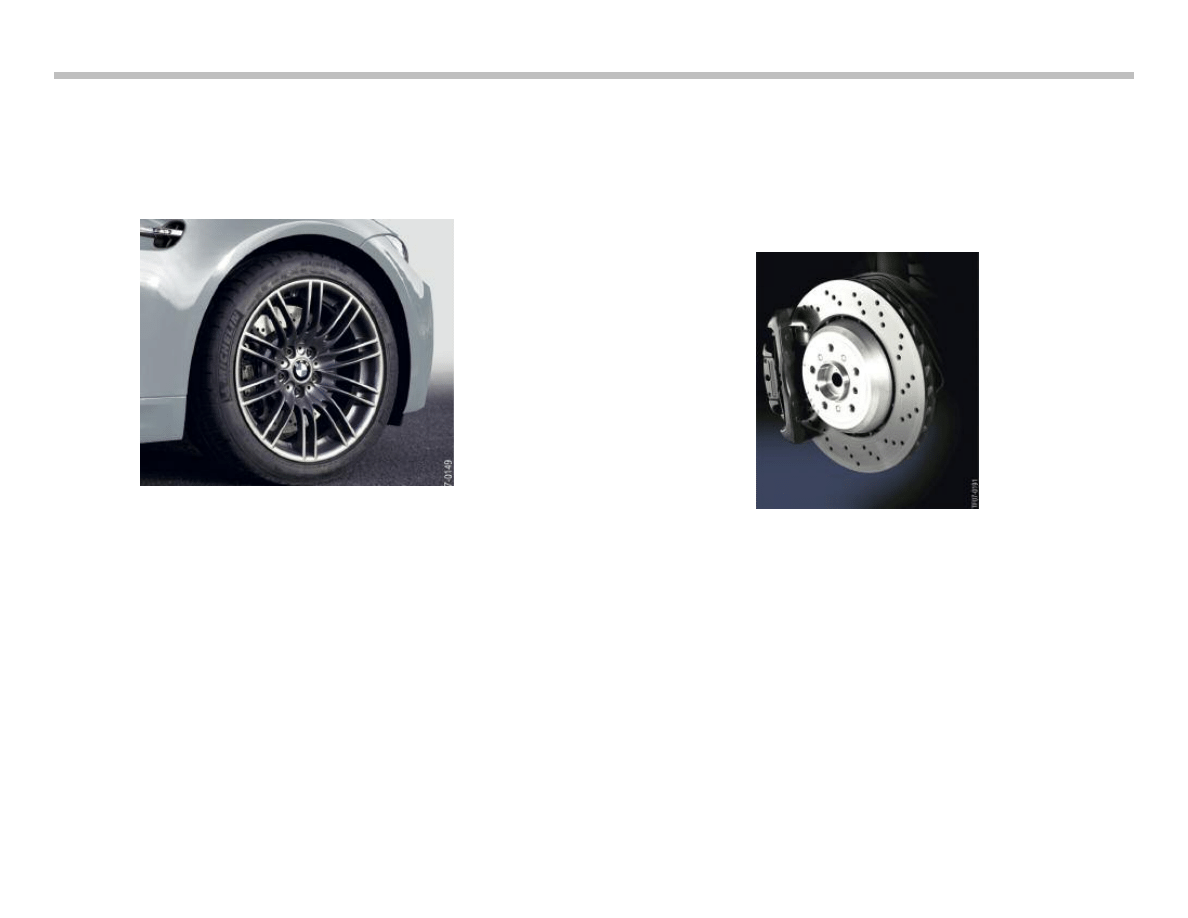
Wheels and Tires
In the standard version, the cast 18" 'M' double spoke wheel (style
260) is available for the E9x M3, with the forged and polished 19"
'M' double-spoke wheel (style 220) available as an option. These
are weight-optimized M3 light alloy wheels.
The tires are also specifically selected for the M3.
The Michelin Pilot Sport (PS2*) is currently fitted.
Wheel/tire Specification
Standard wheel:
Front - Wheel: 8.5 J x 18; IS 29; EH2+
Tires: 245-40 ZR 18
Rear - Wheel: 9.5 J x 18; IS 23; EH2+
Tires: 265-40 ZR 18
Optional:
Front - Wheel: 8.5 J x 19; IS 29; EH2
Tires: 245-35 ZR 19 XL
Rear - Wheel: 9.5 J x 19; IS 23; EH2
Tires: 265-35 ZR 19 XL
Brakes
The M Compound brake system with perforated brake discs and
three 'M'-typical brake pad wear sensors is used, with a specifically
adapted operating principle and dimensions.. The diameter of the
brake discs has increased compared to the E46 M3 by 35 mm at
the front, and by 22 mm at the rear.
Brake System Specification
Front brake: Diameter 360 mm, thickness 30 mm, direction-spe-
cific ventilation, single-piston floating caliper (light-
weight metal alloy), brake pad wear sensor right and
left.
Rear brake: Diameter 350 mm, thickness 24 mm, direction-specif-
ic ventilation, internal handbrake with 185 mm diame-
ter (similar to E60 M5), single-piston floating caliper
(cast metal alloy), brake pad wear sensor on right.

M Chassis and Suspension
25
Dynamic Stability Control (DSC) MK60E5
The E9x M3 is equipped with the MK60E5 DSC system made by
Continental Teves, which has been specifically adapted to its driv-
ing dynamics. The "civilian" version is installed in several non-M
models.
The fundamental difference in both versions is the replacement of
Dynamic Traction Control (DTC) with M Dynamic Mode (MDM).
MDM has been adapted to suit sports car dynamism for experi-
enced sports drivers. The permitted float angle and longitudinal
slip in good environmental conditions (road, weather, etc.) are also
equally high.
Furthermore, the driving-performance control (FLR), soft stop and
Fading Brake Support (FBS) functions are not required in the 'M'
version.
The braking readiness (applies the foot brake and the handbrake
until the discs and drums are dry) and the gradient assistant func-
tions have been adapted appropriately.
Note: An M-specific version of the MK60E5 is installed in
the E6x M5 and M6. For further information regard-
ing DSC systems refer to the Chassis Dynamics
training material available in TIS and ICP.

26
M Chassis and Suspension
NOTES
PAGE
Document Outline
- Main Menu
- 01_M Heritage
- 02_M Complete Vehicles
- 03_M Engines
- 04_M Engine Management System
- 05_M Chassis and Suspension
- 06_M Drivetrain
- 07_M Performance Controls
Wyszukiwarka
Podobne podstrony:
04 1 F01 Chassis and Suspension
05 Culture and cognitionid 5665 Nieznany
05 Structures and Alignment
05 Culture and cognitionid 5665 Nieznany
Edgar Rice Burroughs New Tarzan 05 Tarzan and the Winged Invaders # Barton Werper
Edgar Rice Burroughs Tarzan 05 Tarzan and the Jewels of Opar
Scott, Martin Thraxas 05 Thraxas And The Sorcerers
Clio Braking and Suspension
Ice 05 Fire and Ice Anne Stuart
William Noble Conflict, Action and Suspense
Murray Rothbard 05 Mises and Austrian Economics
2003 05 A Time and a Place
Isaac Asimov Foundation 05 Foundation And Earth
NP R60FE0A SER SM EN 20080602190217734 05 Disassembly and Reassembly
[Damaged 05] Damaged and the Dragon Bijou Hunter
Ian Morson [William Falconer Mystery 05] Falconer and the Great Beast (pdf)
Esther M Friesner A Beltaine And Suspenders
05 Fire and Ice Adron & Livia (2nd Gen)
Nancy Drew 05 Hit And Run Holiday
więcej podobnych podstron