GEOR
GEOR
GEOR
GEOR
GEORGE
GE
GE
GE
GE
Owner's manual
2
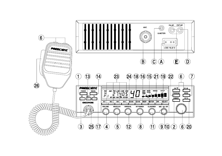
Your PRESIDENT GEORGE at a glance

3
SUMMARY
INSTALLATION
5
HOW TO USE YOUR CB
8
PROTECTION BY SECURITY CODE SYSTEM
14
TECHNICAL CHARACTERISTICS
16
TROUBLE SHOOTING
16
HOW TO TRANSMIT OR RECEIVE A MESSAGE
16
GLOSSARY
17
FREQUENCY TABLES
21

4
The guarantee of this transceiver is valid only in the purchase country.
WARNING !
Before using, be careful never to transmit
without first having connected the
antenna (connection B situated on the
back panel of the equipment) or without
having set the SWR (Standing Wave Ra-
tio) ! Failure to do so may result in destruc-
tion of the power amplifier, which is not
covered by the guarantee.
5
Welcome to the world of the 3
rd
generation of CB radios.
The new PRESIDENT INTERACTIVE range gives you access
to top performance CB equipment. With the use of up-
to-date technology, which guarantees unprecedented
quality, your PRESIDENT GEORGE is a new step in personal
communications and is the surest choice for the most
demanding of professional CB radio users. To ensure
that you make the most of all its capacities, we advise
you to read carefully this manual before installing and
using your PRESIDENT GEORGE.
A) INSTALLATION:
1) WHERE AND HOW TO MOUNT YOUR MOBILE CB RADIO:
a)You should choose the most appropriate setting from a simple and practical
point of view.
b) Your CB radio should not interfere with the driver or the passengers.
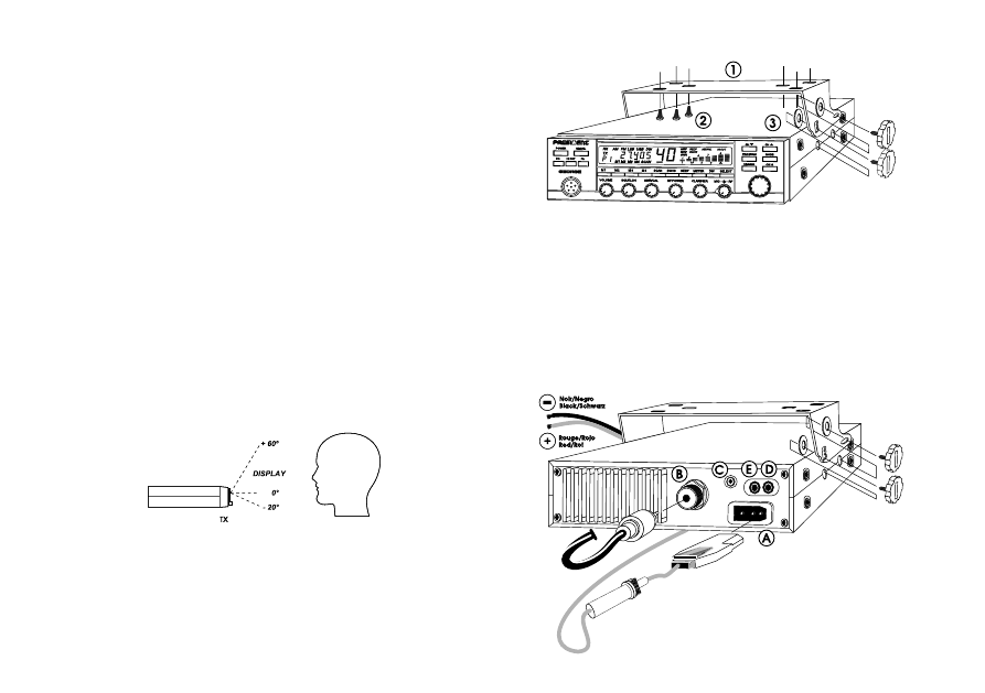
c) Remember that maximum visibility of the LCD display is at an angle of vision
between -20° and +60°.
ANGLE OF VISION
d) Remember to provide for the passing and protection of different wires (e.g.
power, antenna, accessory cabling) so that they do not in any way interfere
with the driving of the vehicle.
e) To mount your CB radio you should use the cradle [1] supplied which must be
firmly fixed using the self-tapping screws [2] provided (drilling diameter 3.2
mm). Take care not to damage the vehicle’s electrical system while drilling
the dash board.
f) Do not forget to insert the rubber joints [3] between the CB and its support as
these have a shock-absorbing effect which permits gentle orientation and
tightening of the set.
g) Choose where to place the microphone support and remember that the
microphone cord must stretch to the driver without interfering with the controls
of the vehicle.
- N.B. : As the transceiver has a frontal microphone socket, you can set it into the
dash board. In this case, you will need to add an external loud speaker to
improve the sound quality of communications (connector EXT.SP situated on
the back panel : D). Ask your dealer for advice on mounting your CB radio.
MOUNTING DIAGRAM
6
2) ANTENNA INSTALLATION:
a) Choosing your antenna:
- For CB radios, the longer the antenna, the better its results. Your dealer will
be able to help you with your choice of antenna.
b) Mobile antenna:
- Must be fixed to the vehicle where there is a maximum of metallic surface
(ground plane), away from windscreen mountings.
- If you already have a radio-telephone antenna installed, the CB antenna
should be higher than this.
- There are two types of antenna : pre-regulated which should be used on a
good ground plane (e.g.
car roof or lid of the boot), and
.
adjustable which offer a much larger range and can be used on a smaller
ground plane (see «How to Adjust SWR», page 41).
- For an antenna which must be fixed by drilling, you will need a good contact
between the antenna and the ground plane. To obtain this, you should lightly
scratch the surface where the screw and tightening star are to
b
e
placed.
- Be careful not to pinch or flatten the coaxial cable (as this runs the risk of break
down and/or short circuiting).
- Connect the antenna (B).
c) Fixed antenna:
- A fixed antenna should be installed in a clear a space as possible. If it is fixed
to a mast, it will perhaps be necessary to stay it, according to the laws in force
(you should seek professional advice). All PRESIDENT antennas and accessories
are designed to give maximum efficiency to each CB radio within the range.
3) POWER CONNECTION:
Your PRESIDENT GEORGE is protected against an inversion of polarities.
However, before switching it on, you are advised to check all the connections.
Your mobile set must be supplied with a continued current of 12 volts (A).
Today, most cars and lorries are negative earth. You can check this by making
sure that the negative terminal of the battery is connected either to the
engine block or to the chassis. If this is not the case, you should consult your
dealer.
WARNING: Lorries generally have two batteries and an electrical installation
of 24 volts, in which case it will be necessary to insert a 24/12 volt converter
(type CV 24/12 PRESIDENT) into the electrical circuit. The following connection
steps should be carried out with the power cable disconnected from the set.
a) Check that the battery is of 12 volts.
b) Locate the positive and negative terminals of the battery (+ is red and - is
black). Should it be necessary to lengthen the power cable, you should use
the same or a superior type of cable.
c) So that you do not have to re-enter the code (security code system) each time
you start the vehicle’s engine, you should connect your CB to a permanent
(+) and (-). We advise you therefore to connect the power cable directly to
the battery (as the connection of the CB cable to the wiring of the car-radio
or other parts of the electrical circuit may, in somecases, increase the
likelihood of interference).
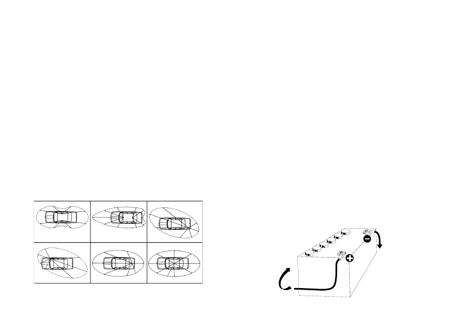
d) Connect the red wire (+) to the positive terminal of the battery and the black
(-) wire to the negative terminal of the battery.
e) Connect the power cable to your CB radio.
WARNING: Never replace the original fuse (5A) by one of a different value.
f) If you disconnect the power supply, the equipment will automatically go into
protection mode and will ask you to re-enter the access code when you re-
connect the power.
OUTPUT RADIUS PATTERNS
Zum
chassis
Connected
to chassis
Zum
starter
Towards
starter
7
4) BASIC OPERATIONS TO BE CARRIED OUT BEFORE USING
YOUR SET FOR THE FIRST TIME (without trans-mitting and
without using the «push-to-talk» switch on the
microphone):
a) Connect the microphone
b) Check the antenna connections
c) To turn the equipment on :
Press any key so that
flashes. You have about 10 seconds in which to
enter your access code.
Press «PROGRAM» key four times (access code pre-determined in the factory).
Each time you press a key, the counter in the display increases by one. Press
the «POWER» key once. Your CB radio will light up and automatically go to
Channel 19, in AM. (MIC GAIN and RF GAIN set to maximum).
If you make a mistake while entering your access code, press any key (several
times, if necessary) until
flashes and then press four times PROGRAM and
then POWER.
d) Turn the squelch knob to minimum (anti-clockwise). Turn the «RF POWER»
switch to maximum (clockwise). Adjust the volume to a comfortable level.
e) Go to Channel 20 using either the «CH
▲» key on the microphone or on the
front panel, or the rotary knob.
5) ADJUSTMENT OF SWR (Standing wave ratio):
WARNING : This must be carried out when you use your CB radio for the first time
(and whenever you re-position your antenna). The adjustment must be
carried out in an obstacle-free area.
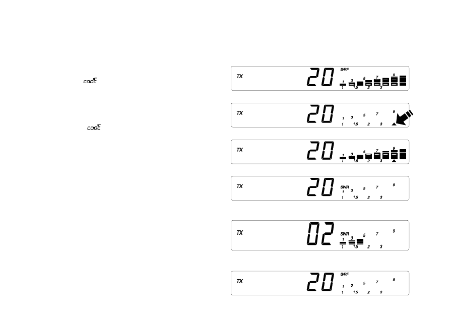
* Using the integrated SWR meter:
For this, carry out the following steps :
a) Press the «push-to-talk» switch on the microphone and keep it pressed down
throughout the adjustment.
b) Press the «METER» key until
▲ appears in the display.
c) Adjust the SWR/CAL key so that
the 7 rows (like a bar graph
▲) appear in the display, with the RF/POWER knob
turned to maximum.
d) Press again the «METER» key so that «SWR» appears in the display and the
▲
disappears. It is now possible to take the SWR reading. If in the display there
are less than three rows of the bar graph, then the SWR reading is acceptable
(1 being the ideal SWR value). If there are Minimum value more than three
rows, we advise you to re-adjust your antenna and re start the procedure from
step a).
e) Press the «METER» key, with the «push-to-talk» switch pressed down, so that the
equipment is in S/RF mode.
DISPLAY
Maximumvalue
Minimum value

8
* Using an external SWR meter (e.g. SWR 1 or SWR 2 PRESIDENT):
a) To connect the SWR meter:
- Connect the SWR meter between the CB radio and the antenna as close as
possible to the CB (use a maximum of 40 cm cable, type CA 2C PRESIDENT).
b) To adjust the SWR meter:
- Set the CB to channel 20.
- Put the switch on the SWR meter to position «CAL» (= calibrate).
- Press the «push-to-talk» switch on the microphone.
- Bring the index needle to
▼ by using the calibration key.
- Change the switch to position SWR (reading of the SWR level). The reading on
the V.U. meter should be as near as possible to 1. If this is not the case, re-adjust
your antenna to obtain a reading as close as possible to 1. (An SWR reading
between 1 and 1.8 is acceptable).
- It will be necessary to re-calibrate after each adjustment of the an-tenna.
Your CB is now ready for use.
B) HOW TO USE YOUR CB:
1) POWER:
a) One quick press on this key turns your CB on and off.
b) A longer depression (about three seconds) activates the protection by code
procedure. The code must be re-entered to put the set on.
NOTE : As soon as your set goes off, the last configuration is memorised ready
for the next time.
2) DIMMER:
a) Set turned off (but with power supply connected): by pressing the DIMMER key
the message
flashes indicating clearly and permanently the code
protection in your absence. You should not leave this function on for more
than three days without starting your vehicle's engine (risk of flat battery).
b) With the set turned on: This key allows you to adjust the luminosity of the display.
3) DC (Double Colour):
With this key you can change the colour of the digital display to either amber
or green, so that your set is in harmony with the interior of your vehicle.
4) VOLUME:
To increase the volume, turn this knob clockwise.
5) SQUELCH:
Suppresses undesirable back-ground noise when there are no
communications. Turn the squelch knob clockwise to the exact point where
all background noise disappears. This adjustment should be done with precision
as, if set to maximum, only the strongest of signals can be received. Squelch
does not effect either sound or transmission power, but allows for considerable
improvement in listening comfort.
6) CHANNEL SELECTOR KEYS «CH
▲
▲
▲
▲
▲», «CH ▼
▼
▼
▼
▼» AND/OR
ROTARY KNOB:
The two keys, «CH
▲» and «CH ▼» on the microphone and on the front panel,
allow you to go up and down the channels. This can also be done with the
channel rotary knob.
«CH
▼» key : one quick press allows you to go down by one channel,
continued pression allows you to descend five channels per second.
«CH
▲» key : one quick press allows you to go up by one channel, continued
pression allows you to ascend five channels per second.
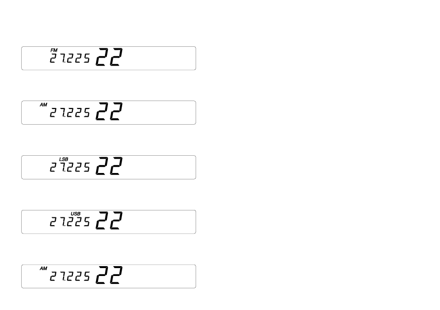
7) MODE:
Use this key to select AM, FM, LSB or USB.
The mode must correspond with that of the person with whom you
communicate.
Amplitude Modulation (AM) is for communications in areas where there are
obstacles and over medium distances.
Frequency Modulation (FM) is for nearby communications in flat, open areas.
It gives better quality of communication (squelch adjustment needs more
finesse).
Lower and Upper Side Band is used for prompt communications over long
distances (depends very much on atmospheric conditions).
A long press on the «MODE» key allows you to change from AM/FM/ to LSB/USB
and vice versa. A short press on the same key allows you to change from AM
to FM or from LSB to USB and vice versa
9
Example:
Configuration
You are in Channel 22, FM.
- Short press on «MODE»:
set goes to Channel 22 AM.
- Longer press on «MODE»:
set goes to Channel 22 FM
then 22 LSB.
- Short press on «MODE»:
set goes to Channel 22 USB.
- Longer press on «MODE»:
set goes to Channel 22 LSB
then 22 AM.
8) RF POWER:
When you turn this knob fully clockwise the RF power (norm peak 4 watts) is at
maximum. You should reduce transmission power when the communication
is close to someone who does not have RF GAIN.
The normal setting of this knob is on maximum (fully clockwise).
9) RF GAIN:
This knob is for adjusting sensitivity during reception. For long distance
communications RF GAIN should be set to maximum. RF GAIN can be
reduced to avoid distortion, when your correspondent is close by and when
he does not have RF POWER.
The normal setting of this knob is on maximum (fully clockwise).
10)MIC GAIN:
a) Is for regulating microphone sensitivity, when using a microphone other than
the one supplied with your PRESIDENT GEORGE. (pre-amplified).
b) Also adjusts the sound volume of Public Address mode (see point 17).
The normal setting of this knob is fully clockwise.
11)CLARIFIER:
This function allows a frequency deviation during LSB/USB reception to improve
the clearness of your correspondent’s voice. This allows a shift of up to 2 kHz
around the reference frequency.
The normal setting of this function is fully clockwise.
12)SWR/CAL:
Used for the calibration of the SWR meter (see «Adjustment of SWR» page 7,
§ 5).
13)HI-CUT:
Cuts out high frequency inter-ference. Its use depends on reception conditions.
Depress the key to use this function, «HICUT» appears in the display. To cancel,
press the same key, «HICUT» disappears from the display.
10
14)NB/ANL:
Noise Blanker/ Automatic Noise Limiter. These filters allow the reduction of
back ground noise, and some reception interference.
Press once to activate the function. «NB/ANL» appears in the display. To
cancel, press the same key. «NB/ANL» disappears from the display.
15)METER:
This key has several functions :
a) Position «S/RF» : for taking a V.U. meter reading of transmission and reception
power ;
b) Position «MODE» only works during transmission. Allows modulation
measurement (voice level).
c) Position
▲ : calibration of the SWR meter.
See «Adjustment of SWR meter» page 7, § 5.
d) Position «SWR» : reading of the SWR value.
See «Adjustment of SWR meter», page 7, § 5.
To use these functions, press the METER key successively in transmission mode.
In reception mode this key locks itself onto position «S/RF».
16)BEEP:
When you finish speaking and you release the «push-to-talk» switch to allow
your correspondent to speak, a «beep» sounds. Radio CB is what is known as
a «simplex» method of communication, that is to say, that you cannot listen
and speak at the same time (as you can, for example, with the telephone).
It was custom to say «roger» to indicate to your correspondent that you’d
finished speaking and that it was his turn to talk. The word «roger» has now
been replaced with a beep, hence its name, «Roger Beep».
By depressing this key once, the roger beep is activated as well as the
sounding of all the keys and the word BEEP appears in the display. To cancel
out the beep, depress the same key. The sound level of the beep can be
adjusted by using the VOLUME knob.
17)PA (Public Address):
An external loud speaker can be connected to your PRESIDENT GEORGE by
the jack plug situated on the back panel PA.SP (E). By pressing the PA key, the
message transmitted into the microphone will be directed towards the
external speaker and be amplified. PA appears in the display and everything
else disappears. Hold the microphone far enough away from this loud
speaker so as to avoid the Larsen effect.
The PA volume is regulated by the MIC GAIN knob. To cancel PA, press the
«PA» key and the set returns to the previous configuration.
18)ECHO:
Use of the echo chamber. This function gives a reverberation (echo) effect to
your voice. The level of echo can be adjusted. Ask your dealer to carry out this
adjustment for you. You can check level of echo either by using the PA
function and connecting a loud speaker, or by carrying out a trial transmission
with a correspondent.
To activate this function press the PA key once. «ECHO» appears in the display.
To cancel it simply press the same key. «ECHO» disappears from the display.
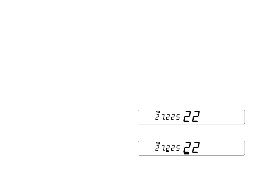
19)SELECT:
The "SELECT" key allows you to go up or down by 10 channels at a time. It is
used in conjunction with the «CH
▲» and «CH ▼» or with the rotary channel
knob.
Example:
Configuration You are in channel 22 FM.
- Press «SELECT» :
Underlining appears in order to indicate Channel 22 FM.
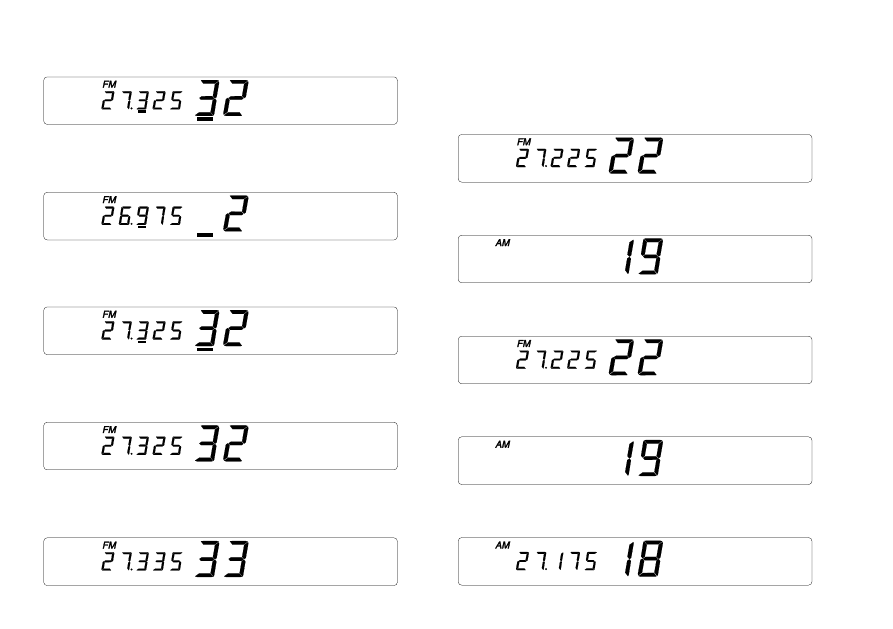
11
- Press «CH
▲» (+ 10 channels):
Set goes to the channel 32 FM.
- Press «CH
▲» (+ 10 channels):
Set goes to the channel 2 FM.
- Press «CH
▼» (- 10 channels):
Set returns to channel 32 FM.
- Press «SELECT» :
Set returns to normal mode.
- Press «CH
▲» (+ 1 channel):
Set goes to channel 33 FM.
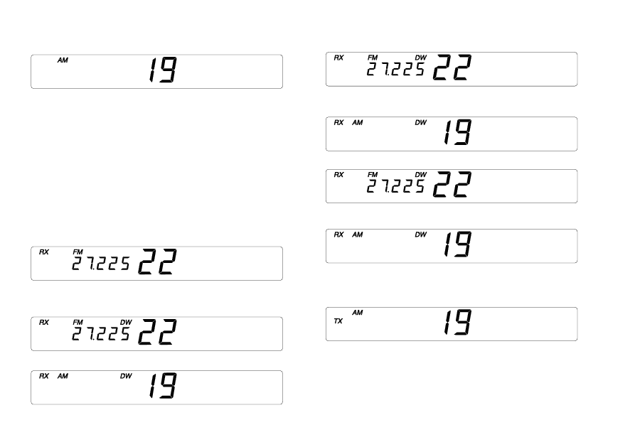
20)CH 19 (Channel 19 AM):
Channel 19 AM is automatically selected when you depress this key.
Configuration
You are in Channel 22 FM.
- Press «CH19»:
Frequency disappears to indicate that Channel 19 AM is selected.
Set goes directly to Channel 19 AM.
- Press «CH19»:
Set returns to previous configuration Channel 22 FM.
- Press «CH19»:
Set goes directly to Channel 19 AM.
- Press «CH
▼»
Set goes down one to Channel 18.
12
- Press «CH19»
Set goes directly to Channel «CH19».
21)DW (Dual Watch):
This function lets you watch over Channel 19 AM and the channel you are
using. The equipment goes to and from the two channels (1 second per
channel) and stops on the one where a signal is detected (reception level
defined by squelch). Dual Watch returns at the end of the signal unless you go
into transmission.
To activate this surveillance function, press «DW». «DW» appears in the display.
To cancel, press the same key. «DW» disappears from the display.
Example:
Configuration
- You are in Channel 22 FM.
- Press «DW».
- If a signal is detected on Channel 22 your CB listens to the channel and stays
there until the end of the signal.
- End of signal on Channel 22 FM.
- Reception of signal on Channel 19 AM.
- Reply to this call by pressing the «push-to-talk» switch on the microphone.
«DW» is cancelled.
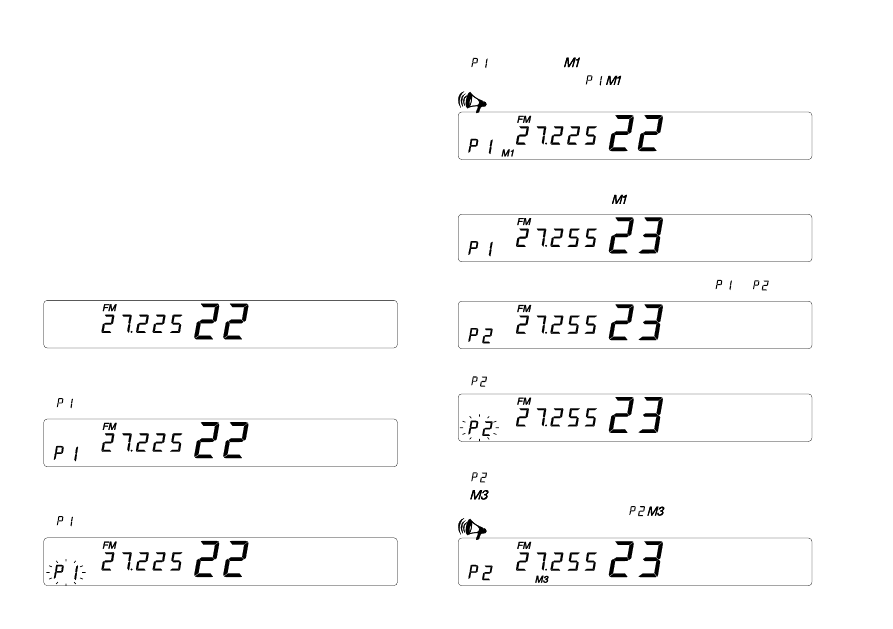
22)PROGRAM:
This key is used in conjunction with keys "M1-M2-M3-M4" and is for memorising
chosen channels.
By rapidly pressing the «PROGRAM» key, P1, P2, P3, P4 will show in the display.
Pressing longer on one of the four keys (P1-P4) will cause the display to flash.
Alternates between
Alternates between
13
By immediately pressing one of the memory keys (M1 - M4) the channel and
the modulation mode currently in use will be stored in the memory. The
operation is validated with a long beep. (See example after paragraph 23)
23)M1-M2-M3-M4:
Used in conjunction with the «PROGRAM» key, these keys allow you to
memorise and to call up information. It is also possible to define the four
memorised channels by using the keys P1 - P4, thus giving a total of 16 possible
memories.
Example:
Configuration
a) How to memorise information
- Initial configuration
Channel 22 FM
- Short depression of c:
appears in the display
- Longer depression of «PROGRAM»
flashes in the display
- Depression of «M1»:
stops flashing,
appears, long beep sounds to indicate that Channel
22 FM is memorised in
.
- Change of channel by depressing one of the keys «CH
▲»/«CH ▼» on the
microphone or front panel.
disappears.
- Rapid depression of «PROGRAM» Set goes from
to
.
- Longer depression of «PROGRAM»
flashes.
- Press «M3»,
stops flashing,
lights up, long beep sounds.
Channel 23 FM is memorised in
.
14
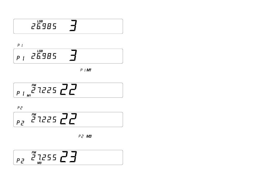
b) Direct access to one of the memories, Initial configuration Channel 3 LSB.
- Rapid depression of «PROGRAM»
appears in the display.
- Depression of «M1»The information in
is called up and the set
automatically goes to the memorised channel (CH 22 FM in our example
above).
- Rapid depression of «PROGRAM»
appears in the display.
- By pressing «M3» the information in
is called up and the set
automatically goes to the memorised setting (CH 23 FM in our example
above).
24)SCAN:
This function allows you to “scan” all the memorised channels (16). Scanning
stops when a signal is detected on one of the memorised channels. At the end
of the signal, scanning continues. By going into transmission mode you may
communicate with your correspondent and your CB leaves the scanning
mode.
This function is activated by depressing the SCAN key and «SCAN» appears in
the display. The level of the signal is defined by using the squelch button. To
cancel, depress the same key, «SCAN» disappears from the display.
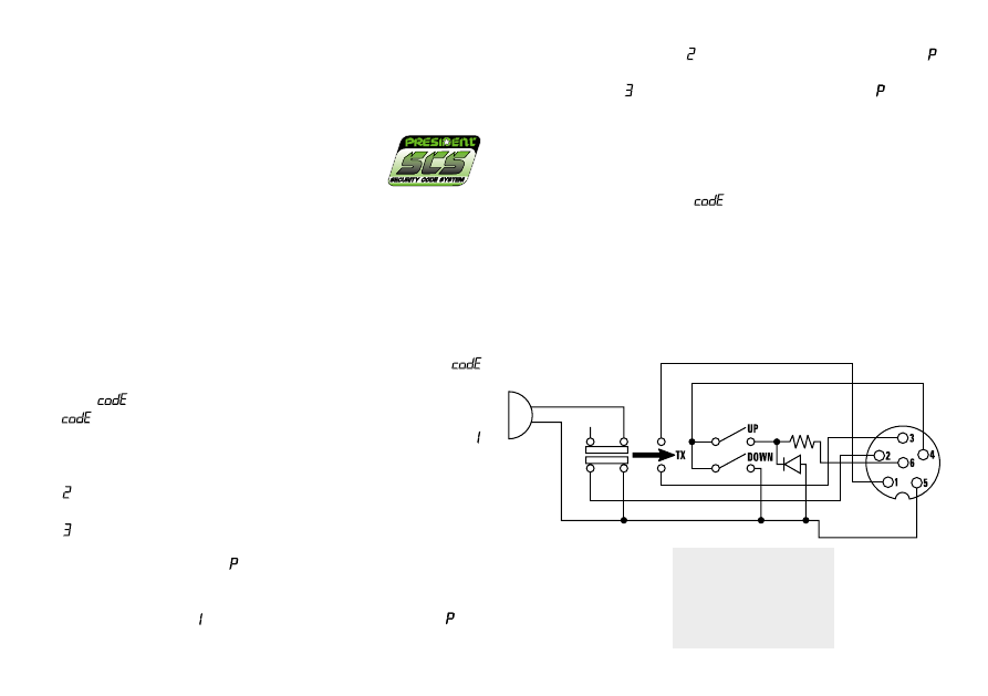
25) 6-PIN MICROPHONE PLUG:
This plug is situated on the front panel, thereby making it easier to set the
equipment into the dashboard. See the cabling diagram on page 21.
26)PTT (push to talk):
Depress this knob to transmit a message and release to listen to an incoming
communication.
A) DC-POWER TERMINAL (13,2 V)
B) ANTENNA CONNECTOR (SO-239)
C) EXTERNAL S-METER JACK (Ø 2,5 mm)
D) EXTERNAL SPEAKER JACK (8
W, Ø 3,5 mm)
E) PA SPEAKER JACK (8
W, Ø 3,5 mm)
C) PROTECTION BY SECURITY CODE SYSTEM:
REMINDER : Your radio CB is automatically protected by a personal 4-digit
access code (security code system) which must be re-entered in the following
circumstances:
15
- if the 12 volt power supply is deconnected
and/or
- after a long depression (more than four seconds) of the POWER key (radio on
or off). In these two cases, the CB is blocked and it is necessary to enter the
correct access code. The access code, established by PRESIDENT in the
factory or after being returned to the After Sales Service department is:
4 short depressions of the
PROGRAM key.
WARNING : If you forget your access code, you are advised to contact your
dealer. We strongly advise you to make a note of your code.
HOW TO PERSONALIZE YOUR ACCESS CODE:
Please carefully read this procedure before changing the access code.
a)Turn your CB on by pressing «POWER».
b)Turn your CB off by pressing «POWER».
c) Depress «POWER» and keep depressed: your CB goes on and then goes off.
d) Depress both «NB/ANL» and «PROGRAM» while keeping «POWER» depressed.
e) Release «POWER», but keeping «NB/ANL» and «PROGRAM» depressed:
flashes in the display for 5 seconds.
f) When
disappears: Release the keys «NB/ANL» and «PROGRAM».
g)
flashes again. You have 20 seconds in which to enter the old code.
h) Press the first key of the old code («PROGRAM» in the original configuration)
appears in the display.
i) Press the second key of the old code («PROGRAM» in the original configuration)
appears in the display.
j) Press the third key of the old code («PROGRAM» in the original configuration)
appears in the display.
k) Press the fourth key of the old code («PROGRAM» in the original configuration).
A beep sounds and the letter
appears in the display which indicates that
your radio CB is ready to register the new code (4 key code).
l) Depress the first key of the new code choosing between «M1», «M2», «M3»,
«M4», and «PROGRAM»: appears in the display as well as the letter
.
m)Depress the second key of the new code choosing between «M1», «M2»,
«M3», «M4», and «PROGRAM»: appears in the display as well as the letter
.
n) Press the third key of the new code choosing between «M1», «M2», «M3», «M4»,
and «PROGRAM»:
appears in the display as well as the letter
.
o) Press the fourth key of the new code choosing between «M1», «M2», «M3»,
«M4», and «PROGRAM» : The display goes out.
p) Depress «POWER»: your CB lights up and the new code is memorised.
- If you make a mistake while entering the old access code, press any key
(several times if necessary) until
flashes in the display and then continue
from step g).
- If, while entering the new access code, you press a key other than «M1», «M2»,
«M3», «M4», or «PROGRAM» (eg SCAN) your CB automatically goes to point l).
6-PIN MICROPHONE PLUG
1
Modulation
2
RX
3
TX
4
Up/Down
5
Masse
6
Alimentation

16
D) TECHNICAL CHARACTERISTICS:
1) GENERAL:
- Channels
:
40
- Modulation modes
:
AM/FM/LSB/USB
- Frequency ranges
:
from 26.965 MHz à 27.405 MHz
- Antenna impedance
:
50 ohms
- Power supply
:
13.2 V
- Dimensions (en mm)
:
200 (L) x 207.5 (H) x 58 (D)
- Weight
:
1.8 kg
- Accessories supplied
:
microphone with support,
mounting cradle, screws.
2) TRANSMISSION:
- Frequency allowance
:
+/- 300 Hz
- Carrier power
:
1 W AM / 4 W FM / 4 W PEP SSB
- Transmission interference
:
inferior to 4 nW (- 54 dBm)
- Audio response
:
300 Hz à 3 KHz in AM/FM/LSB/USB
- Emitted power in the adj. channel
:
inferior to 20 µW
- Microphone sensitivity
:
1 µV
- Drain
:
1,5 A (with modulation)
- Modulated signal distortion
:
2.5%
3) RECEPTION:
- Maxi. sensitivity at 20 dB sinad
:
0.6 µV - 112 dBm (AM/FM)
0.2 µV - 120 dBm (LSB/USB)
- Frequency response
:
300 Hz à 3 kHz in AM/FM/LSB/USB
- Adjacent channel selectivity
:
70 dB
- Maximum audio power
:
3 W
- Squelch sensitivity
:
minimum 0.7 uV - 110 dBm
maximum 1 mV - 47 dBm
- Frequency image rejection rate
:
70 dB
- Intermediate frequency
rejection rate
:
70 dB
- Drain
:
500 mA nominal
800 mA maximum
800 mA nominal
1.3 A
- Maximum Clarifier excursion
:
+/- 2 kHz
E) TROUBLE SHOOTING:
1) YOUR CB RADIO WILL NOT TRANSMIT OR YOUR
TRANSMISSION IS OF POOR QUALITY:
- Check that the PA function is turned off.
- Check that the RF POWER knob is turned fully clockwise.
- Check that the antenna is correctly connected and that the SWR is properly
adjusted.
- Check that the MIC GAIN knob is turned fully clockwise.
- Check that the microphone is properly plugged in.
- With the «push-to-talk» switch activated, the display flashes. Release the
«push-to-talk» switch, then re-press it to go into transmission.
2) YOUR CB RADIO WILL NOT RECEIVE OR RECEPTION IS POOR:
- Check that the PA function is not activated
- Check that the squelch level is properly adjusted.
- Check that the RF GAIN is turned fully clockwise.
- Check that the volume is set to a comfortable listening level.
- Check that the microphone is properly plugged in.
- Check that the antenna is correctly connected and that the SWR is properly
adjusted.
- Check that you are using the same modulation mode as your correspondent.
3)
SHOWS IN THE DISPLAY WHEN YOU GO INTO
TRANSMISSION:
- Check that your power supply is sufficient.
4) YOUR CB WILL NOT LIGHT UP:
- Check the power supply.
- Check the connection wiring.
- Check that you have entered the correct code.
- Check that the POWER button has been pressed.
F) HOW TO TRANSMIT OR RECEIVE A MESSAGE:
Now that you have read the manual, make sure that your CB Radio is ready
for use (i.e. check that your antenna is connected).
Choose your channel (19, 27).
Choose your mode (AM/FM/LSB/USB) which must be the same as that of your
correspondent.
(with LF signal)
(without LF
signal)

17
Press the «push-to-talk» switch and announce your message «Attention sta-
tions, transmission testing» which will allow you to check the clearness and the
power of your signal. Release the switch and wait for a reply. You should
receive a reply like, «Strong and clear».
If you use a calling channel (19, 27) and you have established communication
with someone, it is common practice to choose another available channel so
as not to block the calling channel.
G) GLOSSARY:
Below you will find some of the most frequently used CB radio expressions.
Remember this is meant for fun and that you are by no means obliged to use
them. In an emergency, you should be as clear as possible.
TECHNICAL VOCABULARY:
AM
:
Amplitude Modulation
CB
:
Citizen’s Band
CH
:
Channel
CW
:
Continuous Wave
DX
:
Long Distance Liaison
DW
:
Dual Watch
FM
:
Frequency Modulation
GMT
:
Greenwich Meantime
HF
:
High Frequency
LF
:
Low Frequency
LSB
:
Lower Side Band
RX
:
Receiver
SSB
:
Single Side Band
SWR
:
Standing Wave Ratio
SWL
:
Short Wave Listening
SW
:
Short Wave
TX
:
CB Transceiver
UHF
:
Ultra High Frequency
USB
:
Upper Side Band
VHF
:
Very High Frequency
CB LANGUAGE:
Advertising
:
Flashing lights of police car
Back off
:
Slow down
Basement
:
Channel 1
Base station
:
A CB set in fixed location
Bear
:
Policeman
Bear bite
:
Speeding fine
Bear cage
:
Police station
Big slab
:
Motorway
Big 10-4
:
Absolutely
Bleeding
:
Signal from an adjacent channel
interfering with the transmission
Blocking the channel
:
Pressing the PTT switch without talking
Blue boys
:
Police
Break
:
Used to ask permission to join a
conversation
Breaker
:
A CBer wishing to join a channel
Clean and green
:
Clear of police
Cleaner channel
:
Channel with less interference
Coming in loud and proud
:
Good reception
Doughnut
:
Tyre
Down and gone
:
Turning CB off
Down one
:
Go to a lower channel
Do you copy?
:
Understand?
DX
:
Long distance
Eighty eights
:
Love and kisses
Eye ball
:
CBers meeting together
Good buddy
:
Fellow CBer
Hammer
:
Accelerator
Handle
:
CBer’s nickname
Harvey wall banger
:
Dangerous driver
How am I hitting you?
:
How are you receiving me?
Keying the mike
:
Pressing the PTT switch without talking
Kojac with a kodak
:
Police radar
Land line
:
Telephone
Lunch box
:
CB set
Man with a gun
:
Police radar
Mayday
:
SOS
Meat wagon
:
Ambulance
Midnight shopper
:
Thief
Modulation
:
Conversation
Negative copy
:
No reply
Over your shoulder
:
Right behind you
Part your hair
:
Behave yourself - police ahead
Pull your hammer back
:
Slow down
Rat race
:
Congested traffic
Rubberbander
:
New CBer
Sail boat fuel
:
Wind
Smokey dozing
:
Parked police car
Smokey with a camera
:
Police radar
Spaghetti bowl
:
Interchange
Stinger
:
Antenna
Turkey
:
Dumb CBer
Up one
:
Go up one channel
Wall to wall
:
All over/everywhere
What am I putting to you?
:
Please give me an S-meter reading.
18
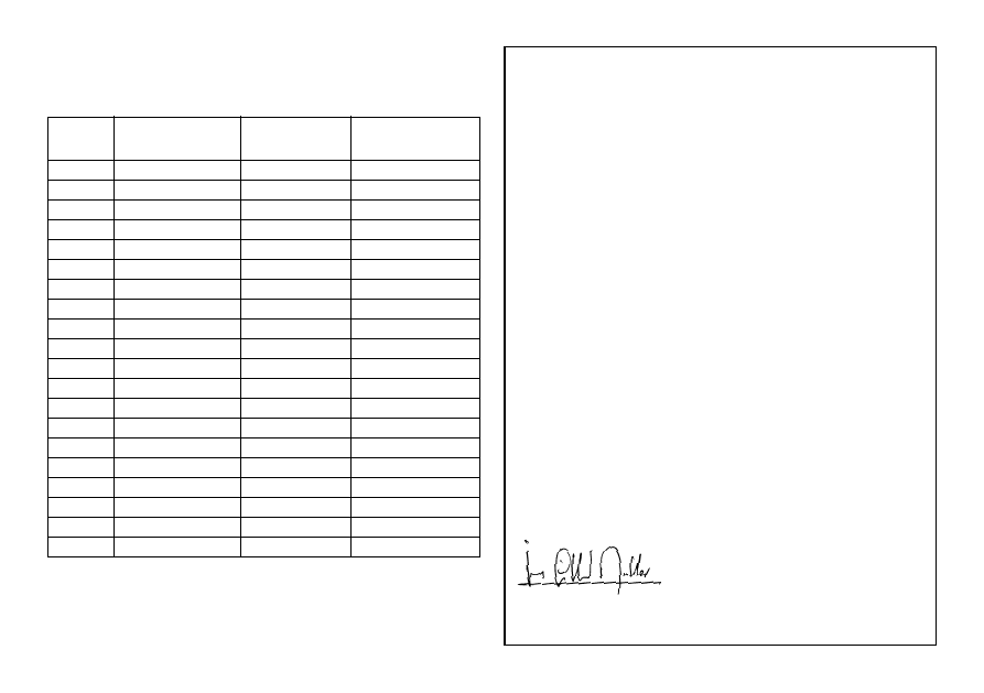
FREQUENCY TABLES
Channel
Frequency
Channel
Frequency
Kanal
Frequenzens
Kanal
Frequenzens
1
26,965 MHz
21
27,215 MHz
2
26,975 MHz
22
27,225 MHz
3
26,985 MHz
23
27,255 MHz
4
27,005 MHz
24
27,235 MHz
5
27,015 MHz
25
27,245 MHz
6
27,025 MHz
26
27,265 MHz
7
27,035 MHz
27
27,275 MHz
8
27,055 MHz
28
27,285 MHz
9
27,065 MHz
29
27,295 MHz
10
27,075 MHz
30
27,305 MHz
11
27,085 MHz
31
27,315 MHz
12
27,105 MHz
32
27,325 MHz
13
27,115 MHz
33
27,335 MHz
14
27,125 MHz
34
27,345 MHz
15
27,135 MHz
35
27,355 MHz
16
27,155 MHz
36
27,365 MHz
17
27,165 MHz
37
27,375 MHz
18
27,175 MHz
38
27,385 MHz
19
27,185 MHz
39
27,395 MHz
20
27,205 MHz
40
27,405 MHz
CERTIFICATE OF CONFORMITY
We, GROUPE PRESIDENT ELECTRONICS, Route de Sète, BP 100
– 34540 Balaruc – FRANCE,
Declare, on our own responsibility that the CB radio-communication
transceiver
Brand : PRESIDENT
Model : GEORGE
Manufactured in the Philippines
is in conformity with the essential requirements of the Directive 1999/
5/CE (Article 3) adapted to the national law, as well as with the
following European Standards:
• ETS 300 135 (1991)
• EN 300 135-2 (2000)
• ETS 300 433 (1995)
• EN 300 433-2 (2000)
Balaruc, the 2001-03-21
Jean-Gilbert MULLER
General Manager
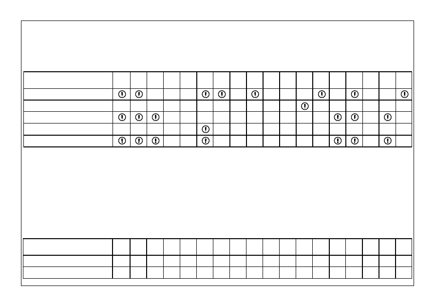
Pays dans lesquels il existe des limitations particulières (Licence
1
/ Registre
2
/ seulement du canal 4 à 12
3
)
Countries in which there are particular restrictions
Países en los cuales existe algún tipo de limitación (Licencia
1
/ Registro
2
/ solo del canal 4 a 12
3
)
Länder mit besonderen Beschränkungen (Lizenz
1
/ Register
2
/ nur Kanal 4 bis 12
3
)
AT BE DK FI FR DE GR IE IT LU NL PT ES SE GB IS NO CH
4W AM
a
a
12W pep BLU
a
a
AT BE DK FI FR DE GR IE IT LU NL PT ES SE GB IS NO CH
Licence
1
Register
2
AM
AM only channels 4 to 12
3
BLU/SSB
Pays dans lequel la réglementation nationale autorise une puissance d’émission supérieure à la limite établie dans la norme harmoni-
sée, précisée dans le quatrième paragraphe de la préface de la norme harmonisée EN 300 433.
Countries in which the national regulations authorize a transmission power superior to the limit fixed by the harmonised
standard, notified in the 4th paragraph of the preface of the proper harmonised standard EN 300 433.
Países en los cuales la reglamentación nacional autoriza una potencia de emisión superior al límite establecido en la norma
harmonizada, advertido en el cuarto parrafo del preámbulo la propia norma armonizada EN 300 433.
Länder in denen die nationale Regelungen ein Sendeleistung zulassen die höher ist als die von der harmonierte Norm
festgelegte Toleranz, angezeigt in 4. Paragraph der Vorrede der harmonierten Norm EN 300 433.
SIEGE SOCIAL/HEAD OFFICE - FRANCE
Route de Sète - BP 100 - 34540 BALARUC
Site Internet : http://www.president-electronics.com
E-mail : groupe@president-electronics.com
0233/03-01
Wyszukiwarka
Podobne podstrony:
PRESIEDENT GEORGE Modyfikacja cz 1
SONY RM AV3000T operating instruction ENG attachment
PRESIEDENT GEORGE Modyfikacja cz 2
Texas Instruments Ti 30xa instruction eng
M000411 B Eng Propulsor painting instructions
Allwinner ENG Brush Instruction Nieznany
instrukcja am2nf3 vsta eng
Instrukcja Eberspaecher Zegar sterujący de eng
Instrukcja obslugi MERCEDES E W124 ENG up by dunaj2
Instrukcja obsługi BMW E38 ENG
Porsche 911 Turbo instrukcja obslugi ENG by mobopx
H000301 A Eng Installation instruction
M000411 B Eng Propulsor painting instructions
Allwinner ENG Brush Instruction Nieznany
więcej podobnych podstron