

INTRODUCTION TO MOSFET AND MOSFET INVERTER
Lab#6
Purpose: Our purpose is to study characteristics of MOSFET and understand the working principle of MOSFET inverter.
Parts/Equipment Needed:
1 BS170 n-channel Enhancement type MOSFET
1kΩ Resistor
500Ω Resistor
Function Generator
Oscilloscope
Breadboard
Multimeter
Power Supply
MOSFET
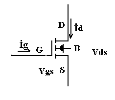
The MOSFET will operate in the triode region if VDS is less than excess gate voltage, that is, if
VDS<VGS-VTR
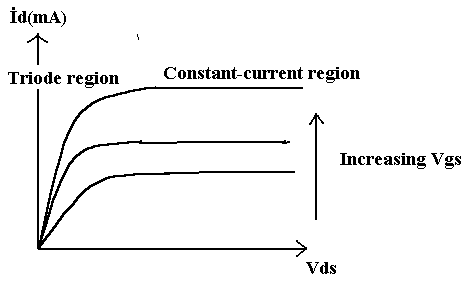
Conversely, the MOSFET will operate in the constant-current region if VDS is greater than the excess gate voltage
VDS>VGS-VTR
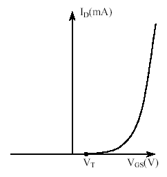
When VGS is smaller than the threshold voltage VTR, the device is said to be in cutoff. In the cutoff condition no current at allcan flow from the drain to the source terminal.
The v-i charactestics of the MOSFET can be summarized by the following equations:
Cutoff region (for VGS< VTR) iD =0
Triode region (VGS>VTR and 0< VDS<VGS-VTR ) iD=K[2(VGS-VTR)VDS-VDS 2 ]
Constant-current region (for VGS<VTR and VDS>VGS-VTR ) iD=K(VGS-VTR)2
PRE-LAB
The inverter of figure-1 utilizes an n-channel enhancement-mode MOSFET with parameters K=1mA/V2 and VTR =2V. The Thevenin circuit consists of a single resistor
RD =500Ω in series with a power supply of value VDD=7.5V. Find the output of the inverter if Vin=3V. Also find the change in output voltage if Vin is increased to 4V, and plot the Vin-Vout transfer characteristic of the inverter.
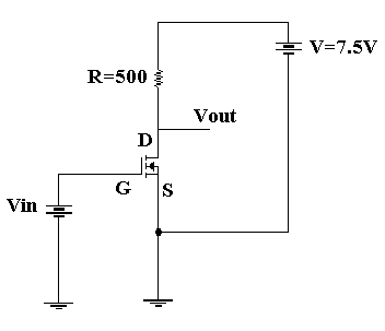
Figure-1
Procedure
1.
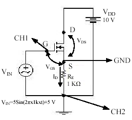
Build the circuit in figure with the given RE, VDD, VIN values.(VIN=5Sin(2πx1kxt)+5 V, RE=2 k,VDD=15 V).
2.Connect CH1 and CH2 scopes as shown in fig. Observe and record ID-VGS graph. (in the X-Y mode,CH1-CH2) (Note that in order to view ID you have to take the inverse of CH2.)
3.Build the circuit in figure-1 with the given R value but take VDD =10V.
4.Increase the Vin from 0V to the value Vout becomes constant. Record these values.
Post-lab
1.By using the obtained ID-VGS graph for n-channel enhancement-type MOSFET in step 2, calculate VT.
2. Draw a graph with data that you collect in step 4. (on the x-axis Vin , y-axis Vout)
3. Show the cutoff, constant-current and triode regions on the graph.
4. Find the gain of inverter from the graph.
Wyszukiwarka
Podobne podstrony:
PP BH&C 0 1 Introduction to the History and Culture of the B
Taylor; Introduction To The Philosophy And Writings Of Plato
SCHAFER, Christian The Philosophy of Dionysius the Areopagite an introduction to the structure and
An Introduction to USA 2 Geographical and Cultural Regions of the USA
Truth and Knowledge Introduction to The Philosophy of Freedom by Rudolf Steiner
Chris Travers The Serpent and the Eagle An Introduction to the Runic Tradition
Guide to the properties and uses of detergents in biology and biochemistry
A Guide to the Law and Courts in the Empire
An Introduction to the Kabalah
Zinda; Introduction to the philosophy of science
IT 0550 US Army Introduction to the Intelligence Analyst
Introduction to the Direct3D 11 Graphics Pipeline
Introduction to the Magnetic Treatment of Fuel
Introduction to the Humanistic Approach
An introduction to the Analytical Writing Section of the GRE
An Introduction to USA 5 Science and Technology
INTRODUCTION TO THE LITERARY THEORY 14
Introduction to the Runes brief background information on runes, with table of Elder Futhark rune m
Cognitive Psychology from Hergenhahn Introduction to the History of Psychology, 2000
więcej podobnych podstron