OBLICZENIA WYTRZYMALOŚCIOWE wałów, Budownictwo-studia, mechanika ogulna


OBLICZANIE

OSI I

WAŁÓW

OBLICZENIA WYTRZYMALOŚCIOWE

OSI I WAŁÓW DWUPODPOROWYCH

METODA PÓŁWYKREŚLNA

METODA ANALITYCZNA

PRZYKŁADY ROZWIĄZAŃ

OPRACOWAŁ

Zasady obliczania osi i wałów dwupodporowych

Obliczanie osi i wałów polega na:

  1. Wyznaczeniu metodami statyki wszystkich sił czynnych i biernych działających na oś lub wał.

  2. Obliczeniu wartości momentów zginających (dla osi i wałów) oraz skręcających i zastępczych (dla wałów) co najmniej dla punktów przyłożenia sił zewnętrznych i dla punktów podparcia (łożysk).

  3. Obliczeniu średnic wału w podstawowych przekrojach i ustaleniu kształtu wału (osi).

  4. Wykonaniu ( w razie potrzeby ) obliczeń sprawdzających (np. uwzględniających zjawisko karbu) i uzupełniających, polegających na obliczeniu sztywności wału itp.

Obliczanie osi dwupodporowych na zginanie

Oś oblicza się jako belkę podpartą na dwóch podporach (łożyskach). Rozwiązanie zaczynamy od wyznaczenia sił czynnych (składowych) a następnie reakcji na podstawie warunków równowagi. Kolejnym krokiem jest wyznaczenie momentów zginających. Następnie na podstawie warunku wytrzymałościowego na zginanie oblicza się minimalną średnicę osi

0x08 graphic

stąd

0x08 graphic

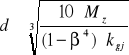
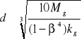
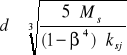
W przypadku projektowania osi drążonych wstępnie zakłada się stosunek średnicy otworu do zewnętrznej średnicy β = do / d = 0,4 ÷ 0,6 jeżeli średnica otworu nie jest uzależniona od wymagań konstrukcyjnych. Średnicę osi oblicza się wg wzoru

0x08 graphic

Obliczanie wałów dwupodporowych na zginanie i skręcanie

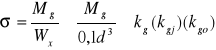
Obciążenie wałów wywołuje w nich naprężenia normalne (zginające) i styczne (skręcające), zatem wały obliczamy ze wzoru na naprężenia zastępcze oparte na hipotezie Hubera

0x08 graphic

Współczynnik redukcyjny α określa, w jakim stopniu uwzględnia się w obliczeniach naprężenia styczne. Jego wartość oblicza się z zależności: α = kgj / ksj lub α = kgo / kso

Ponieważ Wx =-0,1d3 stąd

0x08 graphic

lub dla wału drążonego

0x08 graphic

Obliczanie wałów na skręcanie

Wały obliczamy tylko na skręcanie w następujących sytuacjach;

Średnicę wału obliczamy ze wzoru

0x08 graphic

lub dla wału drążonego

0x08 graphic

PRZYKŁADY ROZWIĄZAŃ

PRZYKŁAD I Zaprojektować wał maszynowy wg schematu przedstawionego na rysunku. Na wale są osadzone koła zębate I i II o średnicach d1 = 10cm i d2 = 20cm . Siła obwodowa na kole I jest pozioma i wynosi F1 = 20000N = 20kN, siła obwodowa na kole II działa w kierunku pionowym i wynosi F2 = 10000N = 10kN. Znaleźć średnicę wału jeżeli naprężenia dopuszczalne kgj = 100Mpa ksj = 70MPa.

0x08 graphic

0x08 graphic
0x08 graphic
0x08 graphic
0x08 graphic
0x08 graphic
0x08 graphic
II

I d1 d2 F1

0x08 graphic
0x08 graphic
0x08 graphic
0x08 graphic
0x08 graphic
0x08 graphic
0x08 graphic
0x08 graphic
0x08 graphic
0x08 graphic
A B

0x08 graphic
0x08 graphic
0x08 graphic
0x08 graphic
0x08 graphic
0x08 graphic
0x08 graphic
0x08 graphic
0x08 graphic
0x08 graphic
0x08 graphic
0x08 graphic
0x08 graphic
0x08 graphic
0x08 graphic
0x08 graphic
x

0x08 graphic
0x08 graphic
0x08 graphic
0x08 graphic
0x08 graphic
0x08 graphic
0x08 graphic
0x08 graphic
0x08 graphic

F2

0x08 graphic
0x08 graphic

10cm 30cm 10cm y

0x08 graphic
0x08 graphic
0x08 graphic

Rozwiązanie metodą półwykreślną

Przyjmujemy podziałkę długości κl = 10 , podziałkę sił κF = 2 kN/cm oraz odległość biegunową H = 3cm = 0,03m.

Obliczamy podziałkę momentów

κm = κl κF H = 10· 2 kN/cm · 0,03m = 0,5kNm/cm

Wprowadzona wartość liczbowa oznacza, że 1cm na wykresie momentów odpowiada 0,5kNm

Wyznaczamy momenty zginające w płaszczyźnie pionowej a następnie poziomej.

W tym celu;

-rysujemy wielobok sił

-znajdujemy reakcje

0x08 graphic

0x08 graphic
0x08 graphic
0x08 graphic
0x08 graphic
0x08 graphic
0x08 graphic
II

I d1 d2 F1

0x08 graphic
0x08 graphic
0x08 graphic
0x08 graphic
0x08 graphic
0x08 graphic
0x08 graphic
0x08 graphic
0x08 graphic
0x08 graphic
A B

0x08 graphic
0x08 graphic
0x08 graphic
0x08 graphic
0x08 graphic
0x08 graphic
0x08 graphic
0x08 graphic
0x08 graphic
0x08 graphic
0x08 graphic
0x08 graphic
0x08 graphic
0x08 graphic
0x08 graphic
0x08 graphic
0x08 graphic
x

0x08 graphic
0x08 graphic
0x08 graphic
0x08 graphic
0x08 graphic
0x08 graphic
0x08 graphic
0x08 graphic
0x08 graphic

F2 F2

0x08 graphic
0x08 graphic

10cm 30cm 10cm y

0x08 graphic
0x08 graphic
0x08 graphic

0x08 graphic
0x08 graphic
0x08 graphic
RAy F2 RBy

0x08 graphic

0x08 graphic
0x08 graphic

0x08 graphic
0x08 graphic
0x08 graphic
0x08 graphic
0x08 graphic
0x08 graphic
0x08 graphic

0x08 graphic
0x08 graphic
1

0x08 graphic
0x08 graphic
F2

0x08 graphic
O1

0x08 graphic
0x08 graphic
0x08 graphic
0x08 graphic
0x08 graphic
z

0x08 graphic
0x08 graphic
2 RA z

0x08 graphic
0x08 graphic

0x08 graphic
Mgy

0x08 graphic
0x08 graphic
0x08 graphic
0x08 graphic
2

1 RB

0x08 graphic

Wyznaczamy momenty zginające w płaszczyźnie poziomej.

0x08 graphic

0x08 graphic
0x08 graphic
0x08 graphic
0x08 graphic
0x08 graphic
0x08 graphic
II

I d1 d2 F1

0x08 graphic
0x08 graphic
0x08 graphic
0x08 graphic
0x08 graphic
0x08 graphic
0x08 graphic
0x08 graphic
0x08 graphic
0x08 graphic
A B

0x08 graphic
0x08 graphic
0x08 graphic
0x08 graphic
0x08 graphic
0x08 graphic
0x08 graphic
0x08 graphic
0x08 graphic
0x08 graphic
0x08 graphic
0x08 graphic
0x08 graphic
0x08 graphic
0x08 graphic
0x08 graphic
0x08 graphic
0x08 graphic
x

0x08 graphic
0x08 graphic
0x08 graphic
0x08 graphic
0x08 graphic
0x08 graphic
0x08 graphic
0x08 graphic
0x08 graphic

F2 F2

0x08 graphic
0x08 graphic

10cm 30cm 10cm y

0x08 graphic
0x08 graphic
0x08 graphic

0x08 graphic
0x08 graphic
0x08 graphic
RAx F1 RBx

0x08 graphic

0x08 graphic
0x08 graphic
0x08 graphic
0x08 graphic
0x08 graphic
0x08 graphic
0x08 graphic
0x08 graphic

Rax 1

0x08 graphic
0x08 graphic
z

0x08 graphic
0x08 graphic

0x08 graphic
0x08 graphic
0x08 graphic
0x08 graphic
0x08 graphic

0x08 graphic
0x08 graphic
0x08 graphic
0x08 graphic
0x08 graphic
0x08 graphic
0x08 graphic
0x08 graphic
z F1 2

0x08 graphic
0x08 graphic
2

Mgx

1

Rbx

0x08 graphic

Sumujemy wykresy momentów zginających

0x08 graphic
0x08 graphic
0x08 graphic
0x08 graphic
0x08 graphic
0x08 graphic

0x08 graphic
0x08 graphic
KOŁO I

0x08 graphic
0x08 graphic
0x08 graphic
0x08 graphic
0x08 graphic
z

0x08 graphic
0x08 graphic
0x08 graphic
0x08 graphic
0x08 graphic
0x08 graphic
2 MGxI

0x08 graphic
0x08 graphic

0x08 graphic
0x08 graphic
Mgy MgyI

0x08 graphic
0x08 graphic
0x08 graphic
MgI

0x08 graphic
0x08 graphic
1

0x08 graphic
0x08 graphic
0x08 graphic
0x08 graphic
0x08 graphic
0x08 graphic
0x08 graphic

0x08 graphic
0x08 graphic
0x08 graphic
0x08 graphic
0x08 graphic
0x08 graphic
0x08 graphic
0x08 graphic
z KOŁO II

0x08 graphic
0x08 graphic
0x08 graphic
2

Mgx MgxII

0x08 graphic
0x08 graphic
0x08 graphic
0x08 graphic
0x08 graphic
1 MgyII

MgII

0x08 graphic

0x08 graphic
0x08 graphic
0x08 graphic
0x08 graphic
0x08 graphic
0x08 graphic
0x08 graphic
0x08 graphic
0x08 graphic
0x08 graphic
0x08 graphic
0x08 graphic
0x08 graphic
0x08 graphic
0x08 graphic
0x08 graphic
0x08 graphic
0x08 graphic

Mg

0x08 graphic

0x08 graphic
0x08 graphic

0x08 graphic
0x08 graphic
0x08 graphic
RYSUJEMY WYKRES

0x08 graphic
0x08 graphic
0x08 graphic
0x08 graphic
0x08 graphic
0x08 graphic
0x08 graphic
0x08 graphic
0x08 graphic
Ms = F1 d1 /2 = F2 d2 /2 =1kNm

Ms

0x08 graphic
0x08 graphic
0x08 graphic

Do znalezienia wykresu momentów potrzebny jest nam moment skręcający z uwzględnieniem współczynnika redukcji α = kgj /ksj = 100MPa/ 70MPa = 1,43

Stąd M`s =α∙ Ms /2 = 1,43∙ 1kNm/2 = 0,715kNm

Kolejnym krokiem będzie zsumowanie wykresów Mg i M`s

0x08 graphic
0x08 graphic
0x08 graphic
0x08 graphic

0x08 graphic
0x08 graphic
0x08 graphic
0x08 graphic
0x08 graphic
0x08 graphic
0x08 graphic
0x08 graphic
0x08 graphic
0x08 graphic
0x08 graphic
0x08 graphic
0x08 graphic
0x08 graphic
0x08 graphic
0x08 graphic
0x08 graphic
0x08 graphic

Mg KOŁO I

0x08 graphic

0x08 graphic
M`s

0x08 graphic
0x08 graphic
0x08 graphic

MgI

0x08 graphic
0x08 graphic
0x08 graphic
MzI

0x08 graphic
0x08 graphic
0x08 graphic

0x08 graphic
0x08 graphic
0x08 graphic
0x08 graphic
0x08 graphic
0x08 graphic
0x08 graphic
0x08 graphic
0x08 graphic
0x08 graphic
0x08 graphic
KOŁO II

M`s

0x08 graphic
M`s

0x08 graphic
0x08 graphic
0x08 graphic
0x08 graphic
0x08 graphic
0x08 graphic

MgII MzII

0x08 graphic
0x08 graphic
0x08 graphic
0x08 graphic
0x08 graphic
0x08 graphic
0x08 graphic
0x08 graphic
0x08 graphic
0x08 graphic
0x08 graphic
0x08 graphic
0x08 graphic
0x08 graphic
0x08 graphic
0x08 graphic
0x08 graphic
0x08 graphic
0x08 graphic
0x08 graphic
0x08 graphic
0x08 graphic
0x08 graphic
0x08 graphic
0x08 graphic

Mz

0x08 graphic

Otrzymane wartości rysunkowe Mz przeliczamy na wartości liczbowe np

MzII = κm∙ (MzII ) = 0,5kNm/cm ∙ 3cm = 1,5 kNm

Po przeliczeniu momentów zastępczych obliczamy średnicę d w przekrojach charakterystycznych oraz w przekrojach dodatkowych korzystając ze wzoru

0x08 graphic
Np.

0x08 graphic

Uwzględniając konstrukcje wału obliczamy średnice w poszczególnych punktach oraz rysujemy zarys wału.

Rozwiązanie metodą rachunkową

Obliczamy momenty zginające w płaszczyźnie pionowej a następnie poziomej.

W tym celu

-obliczamy reakcje

obliczamy momenty zginające

Obciążenie w płaszczyźnie pionowej

0x08 graphic

0x08 graphic
0x08 graphic
0x08 graphic
0x08 graphic
0x08 graphic
0x08 graphic
II

I d1 d2 F1

0x08 graphic
0x08 graphic
0x08 graphic
0x08 graphic
0x08 graphic
0x08 graphic
0x08 graphic
0x08 graphic
0x08 graphic
0x08 graphic
A B

0x08 graphic
0x08 graphic
0x08 graphic
0x08 graphic
0x08 graphic
0x08 graphic
0x08 graphic
0x08 graphic
0x08 graphic
0x08 graphic
0x08 graphic
0x08 graphic
0x08 graphic
0x08 graphic
0x08 graphic
0x08 graphic
0x08 graphic
x

0x08 graphic
0x08 graphic
0x08 graphic
0x08 graphic
0x08 graphic
0x08 graphic
0x08 graphic
0x08 graphic
0x08 graphic

F2 F2

0x08 graphic
0x08 graphic

10cm 30cm 10cm y

0x08 graphic
0x08 graphic
0x08 graphic

0x08 graphic
0x08 graphic
0x08 graphic
RAy F2 RBy

0x08 graphic

0x08 graphic

0x08 graphic
Zapisujemy warunki równowagi;

ΣFiy=0 - Ray + F2 -Rby =0

ΣMia=0 - F2 0,1m +Rby 0,5m =0

Z rozwiązania uzyskujemy; Rby= 2kN , Ray =8kN .

Obliczamy momenty zginające w charakterystycznych punktach;

Mgay = Ray ∙ 0m = 0

MgIy = - Ray ∙0,1m + F2∙0m = - 0,8kNm

MgIIy = - Ray ∙ 0,4m + F2∙0,3m = - 0,2kNm

Mgby = - Ray ∙ 0,5m + F2∙0,4m + Rby∙0m = 0

Wykonujemy wykres momentów zginających

0x08 graphic

0x08 graphic
0x08 graphic
0x08 graphic

0x08 graphic
0x08 graphic
0x08 graphic
0x08 graphic
0x08 graphic
0x08 graphic
0x08 graphic
0x08 graphic
0x08 graphic
0x08 graphic
0x08 graphic
0x08 graphic
0x08 graphic

0x08 graphic
0x08 graphic
0x08 graphic

Mgy [kNm 0,2

0,8

Obciążenie w płaszczyźnie poziomej

0x08 graphic

0x08 graphic
0x08 graphic
0x08 graphic
0x08 graphic
0x08 graphic
0x08 graphic
II

I d1 d2 F1

0x08 graphic
0x08 graphic
0x08 graphic
0x08 graphic
0x08 graphic
0x08 graphic
0x08 graphic
0x08 graphic
0x08 graphic
0x08 graphic
A B

0x08 graphic
0x08 graphic
0x08 graphic
0x08 graphic
0x08 graphic
0x08 graphic
0x08 graphic
0x08 graphic
0x08 graphic
0x08 graphic
0x08 graphic
0x08 graphic
0x08 graphic
0x08 graphic
0x08 graphic
0x08 graphic
0x08 graphic
0x08 graphic
x

0x08 graphic
0x08 graphic
0x08 graphic
0x08 graphic
0x08 graphic
0x08 graphic
0x08 graphic
0x08 graphic
0x08 graphic

F2 F2

0x08 graphic
0x08 graphic

10cm 30cm 10cm y

0x08 graphic
0x08 graphic
0x08 graphic
0x08 graphic

0x08 graphic
0x08 graphic
RAx F1 RBx

0x08 graphic

0x08 graphic

0x08 graphic
Zapisujemy warunki równowagi;

ΣFix=0 - Rax + F1 -Rbx =0

ΣMia=0 - F1 0,4m +Rbx 0,5m =0

Z rozwiązania uzyskujemy; Rbx= 16kN , Rax =4kN .

Obliczamy momenty zginające w charakterystycznych punktach;

Mgax = Rax ∙ 0m = 0

MgIx = - Rax ∙0,1m = - 0,4kNm

MgIIx = - Rax ∙ 0,4m + F2∙0m = - 1,6kNm

Mgbx = - Ray ∙ 0,5m + F2∙0,1m + Rbx∙0m = 0

Wykonujemy wykres momentów zginających

0x08 graphic

0x08 graphic
0x08 graphic
0x08 graphic

0x08 graphic
0x08 graphic
0x08 graphic
0x08 graphic
0x08 graphic
0x08 graphic
0x08 graphic
0x08 graphic
0x08 graphic
0x08 graphic
0x08 graphic
0x08 graphic
0x08 graphic

0x08 graphic
0x08 graphic
0x08 graphic

Mgy [kNm] 0,2

0,8

0x08 graphic
0x08 graphic
0x08 graphic
0x08 graphic
0x08 graphic
0x08 graphic
0x08 graphic
0x08 graphic
0x08 graphic
0x08 graphic
0x08 graphic
0x08 graphic
0x08 graphic
0x08 graphic

0,4

Mgx [kNm]

1,6

0x08 graphic
Wyznaczamy wartość momentów zginających wypadkowych korzystając ze wzoru

Mga = 0

0x08 graphic
0x08 graphic

Mgb = 0

0x08 graphic

0x08 graphic
0x08 graphic
0x08 graphic

0x08 graphic
0x08 graphic
0x08 graphic
0x08 graphic
0x08 graphic
0x08 graphic
0x08 graphic
0x08 graphic
0x08 graphic
0x08 graphic
0x08 graphic
0x08 graphic
0x08 graphic

0x08 graphic
0x08 graphic
0x08 graphic

Mgy [kNm] 0,2

0,8

0x08 graphic
0x08 graphic
0x08 graphic
0x08 graphic
0x08 graphic
0x08 graphic
0x08 graphic
0x08 graphic
0x08 graphic
0x08 graphic
0x08 graphic
0x08 graphic
0x08 graphic
0x08 graphic

0,4

Mgx [kNm]

1,6

0x08 graphic
0x08 graphic
0x08 graphic
0x08 graphic

0x08 graphic
0x08 graphic
0x08 graphic
0x08 graphic
0x08 graphic
0x08 graphic
0x08 graphic
0x08 graphic
0x08 graphic
0x08 graphic
0x08 graphic
0x08 graphic
0x08 graphic
0x08 graphic
0x08 graphic
0x08 graphic

Mg [kNm]0x08 graphic
0,89

1,61

0x08 graphic
0x08 graphic
0x08 graphic
0x08 graphic
1 1 OBLICZAMY WYKRES Ms

0x08 graphic
0x08 graphic
0x08 graphic
0x08 graphic
0x08 graphic
0x08 graphic
0x08 graphic
0x08 graphic
0x08 graphic
Ms = F1 d1 /2 = F2 d2 /2 =1kNm

Ms [kNm]

0x08 graphic

OBLICZAMY WSPÓŁCZYNNIK

REDUKCYJNY α = kgj /ksj =

0x08 graphic
0x08 graphic
0x08 graphic
0x08 graphic
0x08 graphic
0x08 graphic
0x08 graphic
0x08 graphic
0x08 graphic
0x08 graphic
0x08 graphic
0x08 graphic
0x08 graphic
0x08 graphic
0x08 graphic
= 100MPa/ 70MPa = 1,43

OBLICZAMY MOMENTY

0x08 graphic
0x08 graphic
0,89 ZASTĘPCZE ZGODNIE

0x08 graphic
0x08 graphic
Mz [kNm] 1,23 ZE WZOREM

1,61

1.82 Mza = 0

MzIL = 0,89kNm

MzIP = 1.23kNm

MzIIL = 1,82kNm

MzIIP = 1,61kNm

Mzb = 0

0x08 graphic
Obliczamy średnice czopów wału pod łożyska ze wzoru;

0x08 graphic
Podstawiając

Oraz dII = 54,40mm

Przyjmujemy średnice normalne : dI =52mm, dII =56mm

W zależności od konstrukcji łożyskowania dobieramy średnice czopów łożyskowych oraz średnice w punktach dodatkowych.

Uwzględnienie spiętrzenia naprężeń oraz sztywności wału może spowodować zwiększenie założonych średnic.

PRZYKŁAD 2 Zaprojektować wał maszynowy wg schematu przedstawionego na rysunku. Wał jest napędzany przez koło pasowe o średnicy D1 =300mm a odbiór mocy z wału następuje przez koła zębate D2 = 200mm i D3 = 100mm. Moc napędowa P1 = 30kW i jest przekazywana na inne wały przez koło D2 (P2 =20kW) i koło D3 (P3 =10kW) Prędkość obrotowa wału wynosi n = 1400obr/min. Ramiona sił tworzą z dodatnim kierunkiem osi x następujące kąty: α1 =60o , α2 =0o , α3 =270o . Przewidywana praca wału przy częstych zmianach prędkości obrotowej i kierunku obrotów. Materiał stal 20 (nawęglana i hartowana).

0x08 graphic
F1

0x08 graphic
0x08 graphic
D1 α1 =60o

0x08 graphic
0x08 graphic
0x08 graphic
0x08 graphic
D2 D3

0x08 graphic
0x08 graphic
0x08 graphic
0x08 graphic
0x08 graphic
0x08 graphic
0x08 graphic
0x08 graphic
0x08 graphic
0x08 graphic
0x08 graphic
A B

0x08 graphic
0x08 graphic
0x08 graphic
0x08 graphic
0x08 graphic
0x08 graphic
0x08 graphic
0x08 graphic
0x08 graphic
0x08 graphic
α2=0o

0x08 graphic
0x08 graphic
0x08 graphic
0x08 graphic
0x08 graphic
0x08 graphic
0x08 graphic
0x08 graphic
x

0x08 graphic
F3

0x08 graphic
F2

150 200 200 150 α3 =270o

0x08 graphic
0x08 graphic
0x08 graphic
0x08 graphic
y

Rozwiązanie metodą półwykreślną

Wyznaczamy wartości Ms , M`s , F1 ,F2 ,F3, F1x ,F1y metodą rachunkową

Ms1 = 9554∙P1/n = 9554∙30/1400 = 204,7Nm

Ms2 = 9554∙P2/n = 9554∙20/1400 = 136,5Nm

Ms3 = 9554∙P3/n = 9554∙10/1400 = 68,2Nm

M`s1 = (α/2)∙Ms1 gdzie α = kgo /kso = 70MPa/40MPa = 1,75

M`s1 = (α/2)∙Ms1 = (1.75/2)∙204,7 = 153,5Nm

M`s2 = (α/2)∙Ms2 = (1.75/2)∙136,5 = 102.4Nm

M`s3 = (α/2)∙Ms3 = (1.75/2)∙68,2 = 51,1Nm

F1 = Ms1 /(D1/2) = 204,7/(0,3/2) = 1364,7N

F2 = Ms2 /(D2/2) = 136,5/(0,2/2) = 1364,7N

F3 = Ms3 /(D3/2) = 68,2/(0,1/2) = 1364,7N

F1y = F1 ∙cos60o = 682,4N

F1x = F1 ∙sin60o = 1181,9N

Przyjmujemy podziałkę długości κl = 10 , podziałkę sił κF = 500 N/cm oraz odległość biegunową H = 3cm = 0,03m.

Obliczamy podziałkę momentów

κm = κl κF H = 10· 500N/cm · 0,03m = 150Nm/cm

Wprowadzona wartość liczbowa oznacza, że 1cm na wykresie momentów odpowiada 150Nm

Wyznaczamy momenty zginające w płaszczyźnie pionowej a następnie poziomej.

W tym celu;

-rysujemy wielobok sił

-znajdujemy reakcje

-zaznaczamy momenty zginające

0x08 graphic
F1

0x08 graphic
0x08 graphic
D1 α1 =60o

0x08 graphic
0x08 graphic
0x08 graphic
0x08 graphic
0x08 graphic
0x08 graphic
0x08 graphic
D2 D3

0x08 graphic
0x08 graphic
0x08 graphic
0x08 graphic
0x08 graphic
0x08 graphic
0x08 graphic
0x08 graphic
0x08 graphic
0x08 graphic
0x08 graphic
A B

0x08 graphic
0x08 graphic
0x08 graphic
0x08 graphic
0x08 graphic
0x08 graphic
0x08 graphic
0x08 graphic
0x08 graphic
0x08 graphic
0x08 graphic
α2=0o

0x08 graphic
0x08 graphic
0x08 graphic
0x08 graphic
0x08 graphic
0x08 graphic
0x08 graphic
0x08 graphic
x

0x08 graphic
F3

0x08 graphic
F2

150 200 200 150 α3 =270o

0x08 graphic
0x08 graphic
0x08 graphic
0x08 graphic
y

0x08 graphic
0x08 graphic
0x08 graphic
0x08 graphic
0x08 graphic
0x08 graphic

0x08 graphic
0x08 graphic
0x08 graphic
0x08 graphic
F1y Ray F2 Rby

0x08 graphic

0x08 graphic
0x08 graphic
0x08 graphic
0x08 graphic

2

0x08 graphic
0x08 graphic
0x08 graphic
0x08 graphic
0x08 graphic
0x08 graphic
0x08 graphic
0x08 graphic
0x08 graphic
0x08 graphic
0x08 graphic
0x08 graphic
0x08 graphic
0x08 graphic
0x08 graphic
0x08 graphic
1 z F2 F1x

0x08 graphic
0x08 graphic
0x08 graphic
0x08 graphic
0x08 graphic
Mgy 1 O

2 z

3 Rby 3

0x08 graphic

Wyznaczamy momenty zginające w płaszczyźnie poziomej.

0x08 graphic
F1

0x08 graphic
0x08 graphic
0x08 graphic
D1 α1 =60o

0x08 graphic
0x08 graphic
0x08 graphic
0x08 graphic
0x08 graphic
0x08 graphic
0x08 graphic
D2 D3

0x08 graphic
0x08 graphic
0x08 graphic
0x08 graphic
0x08 graphic
0x08 graphic
0x08 graphic
0x08 graphic
0x08 graphic
0x08 graphic
0x08 graphic
A B

0x08 graphic
0x08 graphic
0x08 graphic
0x08 graphic
0x08 graphic
0x08 graphic
0x08 graphic
0x08 graphic
0x08 graphic
0x08 graphic
0x08 graphic
0x08 graphic
0x08 graphic
α2=0o

0x08 graphic
0x08 graphic
0x08 graphic
0x08 graphic
0x08 graphic
0x08 graphic
0x08 graphic
0x08 graphic
x

0x08 graphic
F3

0x08 graphic
F2

150 200 200 150 α3 =270o

0x08 graphic
0x08 graphic
0x08 graphic
0x08 graphic
y

0x08 graphic
0x08 graphic
0x08 graphic
0x08 graphic
0x08 graphic
0x08 graphic

0x08 graphic
0x08 graphic
0x08 graphic
0x08 graphic
F1yx Rax F3 Rbx

0x08 graphic

0x08 graphic
0x08 graphic
0x08 graphic
0x08 graphic

Rbx

0x08 graphic
0x08 graphic
0x08 graphic
0x08 graphic
0x08 graphic
0x08 graphic
1 3

0x08 graphic
0x08 graphic
0x08 graphic
0x08 graphic
0x08 graphic
0x08 graphic
0x08 graphic
0x08 graphic
0x08 graphic
0x08 graphic
0x08 graphic
Mgx 2

0x08 graphic
0x08 graphic
0x08 graphic
3 F3

0x08 graphic
0x08 graphic
0x08 graphic
0x08 graphic
z

0x08 graphic
0x08 graphic
0x08 graphic
0x08 graphic
0x08 graphic
0x08 graphic
0x08 graphic
0x08 graphic
2 O

Rax

F1x

1

0x08 graphic

Sumujemy wykresy momentów zginających

0x08 graphic
0x08 graphic
0x08 graphic
0x08 graphic
0x08 graphic

0x08 graphic
0x08 graphic
0x08 graphic
0x08 graphic
0x08 graphic
0x08 graphic
0x08 graphic
0x08 graphic
0x08 graphic
0x08 graphic
0x08 graphic
0x08 graphic
0x08 graphic
0x08 graphic
0x08 graphic
0x08 graphic
1 z

0x08 graphic
0x08 graphic
0x08 graphic
Mgy PODPORA A

2

0x08 graphic
3 Mgya

0x08 graphic
0x08 graphic
0x08 graphic

0x08 graphic
0x08 graphic
Mgxa

0x08 graphic
0x08 graphic
0x08 graphic
0x08 graphic
0x08 graphic
0x08 graphic
1 Mga

0x08 graphic
0x08 graphic
0x08 graphic
0x08 graphic
0x08 graphic
0x08 graphic
0x08 graphic
0x08 graphic
0x08 graphic
Mgx 2 KOŁO 2

0x08 graphic
0x08 graphic
0x08 graphic
3

0x08 graphic
0x08 graphic
0x08 graphic
0x08 graphic
z Mgy2 =Mg2

0x08 graphic
0x08 graphic
0x08 graphic
0x08 graphic
0x08 graphic

0x08 graphic
0x08 graphic
0x08 graphic
0x08 graphic
0x08 graphic

0x08 graphic
0x08 graphic
0x08 graphic
0x08 graphic
0x08 graphic
0x08 graphic
0x08 graphic
0x08 graphic
KOŁO 3

0x08 graphic
0x08 graphic
0x08 graphic
0x08 graphic
0x08 graphic
0x08 graphic
0x08 graphic
0x08 graphic
0x08 graphic
Mg

0x08 graphic
0x08 graphic
Mgy3

0x08 graphic
0x08 graphic
0x08 graphic

0x08 graphic
Mgx3

Mg3

0x08 graphic
0x08 graphic
0x08 graphic
0x08 graphic
0x08 graphic
0x08 graphic
0x08 graphic
0x08 graphic
0x08 graphic
0x08 graphic
0x08 graphic
0x08 graphic
0x08 graphic
RYSUJEMY WYKRES

M`s 1cm =150Nm

0x08 graphic
0x08 graphic
0x08 graphic
0x08 graphic
0x08 graphic
0x08 graphic
Ms`

0x08 graphic

SUMUJEMY WYKRESY

Mg i M`s

KOŁO 1

Mz =M`s

0x08 graphic
0x08 graphic
0x08 graphic
0x08 graphic
0x08 graphic

0x08 graphic
0x08 graphic
0x08 graphic
0x08 graphic
0x08 graphic
0x08 graphic
0x08 graphic
0x08 graphic
0x08 graphic
0x08 graphic

0x08 graphic
0x08 graphic
0x08 graphic
PODPORA A

0x08 graphic
0x08 graphic
0x08 graphic
0x08 graphic
0x08 graphic
0x08 graphic
M`s1

0x08 graphic
0x08 graphic
0x08 graphic
Mz

Mga

0x08 graphic
Mza

KOŁO 2

LEWA PRAWA

0x08 graphic
M`s1 M`s3

0x08 graphic
0x08 graphic
0x08 graphic
0x08 graphic
0x08 graphic
0x08 graphic
0x08 graphic

0x08 graphic
0x08 graphic
Mg2 Mz2l Mg2 Mz2p

KOŁO 3

LEWA PRAWA

0x08 graphic
M`s3

0x08 graphic
0x08 graphic
0x08 graphic
0x08 graphic

0x08 graphic
Mg3 Mz3l Mg3 =Mz3p

Otrzymane wartości rysunkowe Mz przeliczamy na wartości liczbowe np.

Mz2l = κm∙ (Mz2l ) = 150Nm/cm ∙ 2.1cm = 315 Nm

Po przeliczeniu momentów zastępczych obliczamy średnicę d w przekrojach charakterystycznych oraz w przekrojach dodatkowych korzystając ze wzoru

0x08 graphic

0x08 graphic
Np.

Uwzględniając konstrukcję wału obliczamy średnice w poszczególnych punktach oraz rysujemy zarys wału.

Rozwiązanie metodą rachunkową

Obliczamy momenty zginające w płaszczyźnie pionowej a następnie poziomej.

W tym celu

-obliczamy reakcje

obliczamy momenty zginające

Obciążenie w płaszczyźnie pionowej

0x08 graphic
F1

0x08 graphic
0x08 graphic
D1 α1 =60o

0x08 graphic
0x08 graphic
0x08 graphic
0x08 graphic
0x08 graphic
0x08 graphic
0x08 graphic
D2 D3

0x08 graphic
0x08 graphic
0x08 graphic
0x08 graphic
0x08 graphic
0x08 graphic
0x08 graphic
0x08 graphic
0x08 graphic
0x08 graphic
0x08 graphic
A B

0x08 graphic
0x08 graphic
0x08 graphic
0x08 graphic
0x08 graphic
0x08 graphic
0x08 graphic
0x08 graphic
0x08 graphic
0x08 graphic
0x08 graphic
α2=0o

0x08 graphic
0x08 graphic
0x08 graphic
0x08 graphic
0x08 graphic
0x08 graphic
0x08 graphic
0x08 graphic
0x08 graphic
x

0x08 graphic
0x08 graphic
F3

0x08 graphic
0x08 graphic
F2

150 200 200 150 α3 =270o

0x08 graphic
0x08 graphic
0x08 graphic
0x08 graphic
y

0x08 graphic
0x08 graphic
0x08 graphic
0x08 graphic
0x08 graphic

0x08 graphic
F1y Ray F2 Rby

0x08 graphic

Wyznaczamy wartości Ms , M`s , F1 ,F2 ,F3, F1x ,F1y ;

Ms1 = 9554∙P1/n = 9554∙30/1400 = 204,7Nm

Ms2 = 9554∙P2/n = 9554∙20/1400 = 136,5Nm

Ms3 = 9554∙P3/n = 9554∙10/1400 = 68,2Nm

M`s1 = (α/2)∙Ms1 gdzie α = kgo /kso = 70MPa/40MPa = 1,75

M`s1 = (α/2)∙Ms1 = (1.75/2)∙204,7 = 153,5Nm

M`s2 = (α/2)∙Ms2 = (1.75/2)∙136,5 = 102.4Nm

M`s3 = (α/2)∙Ms3 = (1.75/2)∙68,2 = 51,1Nm

F1 = Ms1 /(D1/2) = 204,7/(0,3/2) = 1364,7N

F2 = Ms2 /(D2/2) = 136,5/(0,2/2) = 1364,7N

F3 = Ms3 /(D3/2) = 68,2/(0,1/2) = 1364,7N

F1y = F1 ∙cos60o = 682,4N

F1x = F1 ∙sin60o = 1181,9N

0x08 graphic
Zapisujemy warunki równowagi;

ΣFiy=0 -F1y - Ray + F2 - Rby =0

ΣMia=0 -F1y ∙ 0,15m +Ray ∙0m - F2 0,2m +Rby 0,55m =0

Z rozwiązania uzyskujemy; Rby= 682,4N , Ray = 0N .

Obliczamy momenty zginające w charakterystycznych punktach;

Mg1y = F1y ∙0m = 0

Mgay = -F1y ∙0,15m + Ray ∙ 0m = - 102,4Nm

Mg2y = -F1y ∙ 0,35m - Ray ∙0,2m + F2∙0m = - 238,8Nm

Mg3y = -F1y∙ 0,55m - Ray ∙ 0,4m + F2∙0,2m = - 102,4Nm

Mgby = -F1y ∙ 0,7m - Ray ∙ 0,55m + F2∙0,35m + Rby∙0m = 0

Wykonujemy wykres momentów zginających

0x08 graphic
0x08 graphic
0x08 graphic
0x08 graphic
0x08 graphic
0x08 graphic
238,8

0x08 graphic
0x08 graphic
0x08 graphic
0x08 graphic
0x08 graphic
102,4 102,4

0x08 graphic
0x08 graphic

0x08 graphic
0x08 graphic
0x08 graphic
0x08 graphic
0x08 graphic
0x08 graphic
0x08 graphic
0x08 graphic
0x08 graphic
0x08 graphic
0x08 graphic
0x08 graphic

Mgy

Obciążenie w płaszczyźnie poziomej

0x08 graphic
F1

0x08 graphic
0x08 graphic
0x08 graphic
D1 α1 =60o

0x08 graphic
0x08 graphic
0x08 graphic
0x08 graphic
0x08 graphic
0x08 graphic
0x08 graphic
D2 D3

0x08 graphic
0x08 graphic
0x08 graphic
0x08 graphic
0x08 graphic
0x08 graphic
0x08 graphic
0x08 graphic
0x08 graphic
0x08 graphic
0x08 graphic
A B

0x08 graphic
0x08 graphic
0x08 graphic
0x08 graphic
0x08 graphic
0x08 graphic
0x08 graphic
0x08 graphic
0x08 graphic
0x08 graphic
0x08 graphic
0x08 graphic
0x08 graphic
α2=0o

0x08 graphic
0x08 graphic
0x08 graphic
0x08 graphic
0x08 graphic
0x08 graphic
0x08 graphic
0x08 graphic
x

0x08 graphic
F3

0x08 graphic
0x08 graphic
0x08 graphic
F2

0x08 graphic
150 200 200 150 α3 =270o

0x08 graphic
0x08 graphic
0x08 graphic
0x08 graphic
y

0x08 graphic
0x08 graphic
0x08 graphic
0x08 graphic
0x08 graphic

0x08 graphic
F1x Rax F3 Rbx

0x08 graphic

0x08 graphic
Zapisujemy warunki równowagi;

ΣFiy=0 -F1x - Rax - F3 - Rbx =0

ΣMia=0 -F1x ∙ 0,15m +Rax ∙0m + F3 0,4m +Rbx 0,55m =0

Z rozwiązania uzyskujemy; Rbx= - 668,2N , Rax = - 1878,4N .

Obliczamy momenty zginające w charakterystycznych punktach;

Mg1x = F1x ∙0m = 0

Mgax = -F1x ∙0,15m + Ray ∙ 0m = - 177,3Nm

Mg2x = -F1x ∙ 0,35m - Rax ∙0,2m = - 38,0Nm

Mg3x = -F1x∙ 0,55m - Rax ∙ 0,4m + F3∙0m = 101,3Nm

Mgbx = -F1x ∙ 0,7m - Rax ∙ 0,55m + F3∙0,15m - Rbx∙0m = 0

Wykonujemy wykres momentów zginających

0x08 graphic
0x08 graphic
0x08 graphic
0x08 graphic
0x08 graphic
0x08 graphic
177,3

0x08 graphic
0x08 graphic
0x08 graphic
0x08 graphic
0x08 graphic
0x08 graphic
0x08 graphic
38,0

0x08 graphic
0x08 graphic
0x08 graphic
0x08 graphic
0x08 graphic
0x08 graphic
0x08 graphic
0x08 graphic
0x08 graphic
0x08 graphic
Mgx

0x08 graphic

0x08 graphic

101,3

0x08 graphic
Wyznaczamy wartość momentów zginających wypadkowych korzystając ze wzoru

0x08 graphic
Mg1 = 0

0x08 graphic

0x08 graphic

Mgb = 0

0x08 graphic
0x08 graphic
0x08 graphic
0x08 graphic
0x08 graphic
0x08 graphic
238,8

0x08 graphic
0x08 graphic
0x08 graphic
0x08 graphic
0x08 graphic
102,4 102,4

0x08 graphic
0x08 graphic

0x08 graphic
0x08 graphic
0x08 graphic
0x08 graphic
0x08 graphic
0x08 graphic
0x08 graphic
0x08 graphic
0x08 graphic
0x08 graphic
0x08 graphic
0x08 graphic
0x08 graphic

Mgy Nm

0x08 graphic

0x08 graphic
0x08 graphic
0x08 graphic

0x08 graphic
0x08 graphic
0x08 graphic
0x08 graphic
0x08 graphic
0x08 graphic
177,3

0x08 graphic
0x08 graphic
0x08 graphic
0x08 graphic
0x08 graphic
0x08 graphic
0x08 graphic
38,0

0x08 graphic
0x08 graphic
0x08 graphic
0x08 graphic
0x08 graphic
0x08 graphic
0x08 graphic
0x08 graphic
0x08 graphic
0x08 graphic
Mgx Nm

0x08 graphic
0x08 graphic
0x08 graphic

0x08 graphic
0x08 graphic
0x08 graphic

101,3

241,7

0x08 graphic
0x08 graphic
0x08 graphic
0x08 graphic
204,7

0x08 graphic
0x08 graphic
0x08 graphic
0x08 graphic
0x08 graphic
144,0

0x08 graphic
0x08 graphic
0x08 graphic
0x08 graphic
Mg Nm

0x08 graphic
0x08 graphic

0x08 graphic
0x08 graphic
0x08 graphic
0x08 graphic
0x08 graphic
0x08 graphic
0x08 graphic
0x08 graphic
0x08 graphic
0x08 graphic
0x08 graphic
0x08 graphic
204,7 RYSUJEMY WYKRES

68,2 Ms 1cm =150Nm

0x08 graphic
0x08 graphic
0x08 graphic
0x08 graphic
Ms Nm

0x08 graphic

0x08 graphic
OBLICZAMY MOMENTY ZASTĘPCZE ZGODNIE ZE WZOREM

Gdzie α = kgo /kso = 70MPa/40Mpa = 1,75
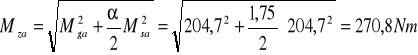
0x08 graphic
0x08 graphic

0x08 graphic
0x08 graphic
0x08 graphic
0x08 graphic
Mzb = 0

299,7

0x08 graphic
0x08 graphic
0x08 graphic
0x08 graphic
0x08 graphic
0x08 graphic
0x08 graphic
0x08 graphic
0x08 graphic
0x08 graphic
270,8 248,8

0x08 graphic
0x08 graphic
0x08 graphic
0x08 graphic
0x08 graphic
159,3

0x08 graphic
177,3

0x08 graphic
0x08 graphic
144

0x08 graphic
0x08 graphic
0x08 graphic
Mz Nm

0x08 graphic
Obliczamy średnice czopów wału pod łożyska ze wzoru;

0x08 graphic
Podstawiając

0x08 graphic

0x08 graphic

Przyjmujemy średnice normalne : dA =35mm, d2 =38mm , d3 =30mm.

W zależności od konstrukcji łożyskowania dobieramy średnice czopów łożyskowych oraz średnice w punktach dodatkowych.

Uwzględnienie spiętrzenia naprężeń oraz sztywności wału może spowodować zwiększenie założonych średnic.

0x01 graphic

0x01 graphic

0x01 graphic

0x01 graphic

0x01 graphic

0x01 graphic

0x01 graphic

0x01 graphic

0x01 graphic

0x01 graphic

0x01 graphic

0x01 graphic

0x01 graphic

0x01 graphic

0x01 graphic

0x01 graphic

0x01 graphic

0x01 graphic

0x01 graphic

0x01 graphic

0x01 graphic

0x01 graphic

0x01 graphic

0x01 graphic

0x01 graphic

0x01 graphic

0x01 graphic

0x01 graphic

0x01 graphic

0x01 graphic

0x01 graphic

0x01 graphic

0x01 graphic


Wyszukiwarka