Slajd12 (174)
MC6840 TIMER COUNTER
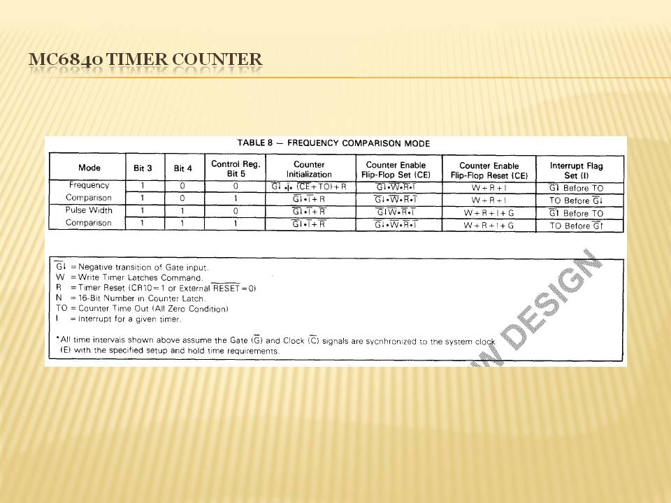
TABLE 8 - FREOUENCY COMPARlSON MODĘ
|
Modę |
Bit 3 |
Bit 4 |
Control Reg. Bit 5 |
Counter Initialization |
Counter Enable Flip-Flop Set ICE) |
Counter Enable Flip-Flop Reset łCEł |
Interrupt Flag Set (I) |
|
Freguency |
1 |
0 |
0 |
G* *|« iCt+TOI+R |
G l |
W + R +1 |
G1 Bofore TO |
|
Corrpanson |
1 |
0 |
1 |
Gl.T+R |
Gł • |
W+R + l |
TO Befcre Gi |
|
Pulse Width |
1 |
1 |
0 |
"5*1 • 1 + R |
G1 W*R*I |
W + R + l+G |
Gt Before TO |
|
Companson |
1 |
1 |
1 |
G1 • + R |
G • • W • R • 1 |
W + R 1 + G |
TO Before (Tf |

Gł = Negaiive trarsnion o‘ Gate mpu:
W =Write Timer Latches Command. _
R =Timer Reset (CR‘iO = I or £xi9rna! RESET = 01 N = 16-Bit Number in Counter Latch TO = Counter Time Out (Ali Zerc Condition)
I = Interrypt for a given timer.
'Ali time intervals shown above assume tbe Gate (G) and Clock iC) signals are sycnhronized to the system doi (Eł with the speofied setup and hołd time requ>rements
Wyszukiwarka
Podobne podstrony:
13657 Slajd10 (177) MC6840 TIMER COITNTER V. . CRX4 TABLE 3 - PTM OPERATING MODĘ SELECTION 0 0 0 C
Slajd5 (116) VSS[ G 2 [ 02 [ £2[ G3 t 03 [ C3 [MC6840 TIMER COUNTER T r R
53052 Slajd9 (122) MC6840 TIMER COUNTER FUNKCJE BITÓW REJESTRÓW STERUJĄCYCH
IMGf14 (3) 70 Budowa i działanie mikrokontrolerów A VR0CR1AH i 0CR1AL (Timer/Counterl Output Compare
f6 4 j IV7 j Table history - comparison with current stale fVertical Split) labie Edit Goto Display
00146 &5dd89e4c9f1d1c9b9ade934fbf44bb 147 Optimization and Sensitivity Analysis Table 10. Compariso
Slajd13 (174) MAX68l8 Humań Body ESD Test Model IECiooo-4-2 ESD Test Model
25711 Slajd15 (174) MCF5407- REJESTR STATUSOWY 15 u 13 12 11 10 9 8 7 6 5 4 3 2 1 0 System
86263 IMGf15 (4) 71 Timery/licznikii ICR1L (Timer/Counterl Input Capture Register) - starszy i młods
więcej podobnych podstron