p57
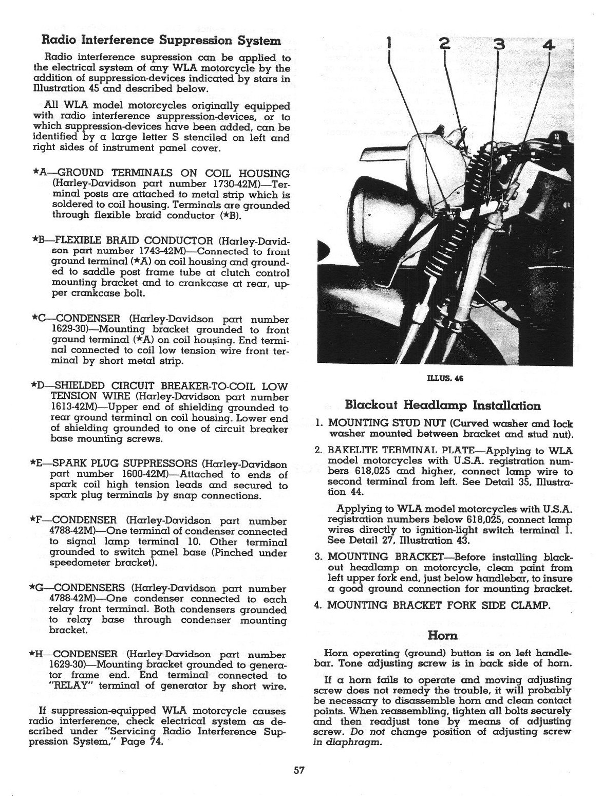
ILLUS. 46
Radio Interference Suppression System
Radio interference supression can be applied to the electrical system of any WLA motorcycle by the addition of suppression-devices indicated by stars in Illustration 45 and described below.
Ali WLA model motorcycles originally eąuipped with radio interference suppression-devices, or to which suppression-devices have been added, can be identified by a large letter S stenciled on left and right sides of instrument panel cover.
★A—GROUND TERMINALS ON COIL HOUSING (Harley-Davidson part number 1730-42M)—Terminal posts are attached to metal strip which is soldered to coil housing. Terminals are grounded through flexible braid conductor (*B).
*B—FLEXIBLE BRAID CONDUCTOR (Harley-David-son part number 1743-42M)—Connected to fiont ground terminal (*A) on coil housing and grounded to saddle post frame tubę at clutch control mounting bracket and to crankcase at rear, up-per crankcase bolt.
*C—CONDENSER (Harley-Davidson part number 1629-30)—Mounting bracket grounded to front ground terminal (*A) on coil housing. End terminal connected to coil Iow tension wire front terminal by short metal strip.
*D—SHIELDED CIRCUIT BREAKER-TO-COIL LOW TENSION WIRE (Harley-Davidson part number 1613-42M)—Upper end of shielding grounded to rear ground terminal on coil housing. Lower end of shielding grounded to one of Circuit breaker base mounting screws.
*E—SPARK PŁUG SUPPRESSORS (Harley-Davidson part number 1600-42M)—Attached to ends of spark coil high tension leads and secured to spark pług terminals by snap connections.
*F—CONDENSER (Harley-Davidson part number 4788-42M)—One terminal of condenser connected to signal lamp terminal 10. Other terminal grounded to switch panel base (Pinched under speedometer bracket).
*G—CONDENSERS (Harley-Davidson part number 4788-42M)—One condenser connected to each relay front terminal. Both condensers grounded to relay base through condenser mounting bracket.
*H—CONDENSER (Harlcy-Davidson part number 1629-30)—Mounting bracket grounded to generator frame end. End terminal connected to "RELAY" terminal of generator by short wire.
If suppression-eąuipped WLA motorcycle causes radio interference, check electrical system as described under "Servicing Radio Interference Suppression System," Page 74.
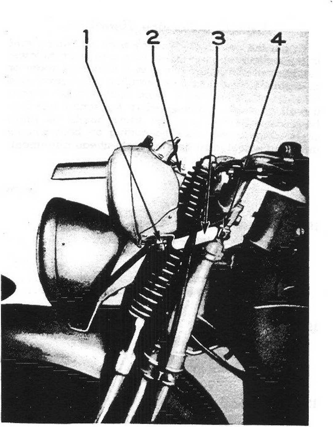
Blackout Headlamp Installation
1. MOUNTING STUD NUT (Curved washer and lock washer mounted between bracket and stud nut).
2. BAKELITE TERMINAL PLATĘ—Applying to WLA model motorcycles with U.S.A. registration num-bers 618,025 and higher, connect lamp wire to second terminal from left. See Detail 35, Illustra-tion 44.
Applying to WLA model motorcycles with U.S.A. registration numbers below 618,025, connect lamp wires directly to ignition-light switch terminal 1. See Detail 27, Illustration 43.
3. MOUNTING BRACKET—Before installing blackout headlamp on motorcycle, clecm paint from left upper fork end, just below handlebar, to insure a good ground connection for mounting bracket.
4. MOUNTING BRACKET FORK SIDE CLAMP.
Horn
Horn operating (ground) button is on left handlebar. Tonę adjusting screw is in back side of hom.
If a hom fails to operate and moving adjusting screw does not remedy the trouble, it will probably be necessary to disassemble hom and clean contact points. When reassembling, tighten all bolts securely and then readjust tonę by means of adjusting screw. Do not change position of adjusting screw in diaphragm.
57
Wyszukiwarka
Podobne podstrony:
FIELD INSTRUMENTS IN MEASUREMENT SYSTEMS Level transmitters can be xnnected to the MultiCONT prxess
Because all relevant settings can be madę using the web interface, this manuał refers to configurati
clients, offer a management interface and can be used in combination with Timer services to launch s
clients, offer a management interface and can be used in combination with Timer services to launch s
mbs 111 MY BREATHING SYSTEM practised until it can be periormcd unconsciously. I havc never seen thi
20 Paweł Antonowicz the effective CRM system must play various different functions. According to the
77450 system 62 62 wards, until the seat touches the heels. The arras should simultaneously be lower
52763 mbs 074 MY BREATHING SYSTEM respect. may in reality prove harmful to the vital organs of indiv
system 22 22 later as most strengthening to the digestion and the intestinal functions. There are ot
cablemotpro GENERAL INFORMATION The RKN4074 ProgrammingTest Cable connectsthe radio to the RLN4008 R
więcej podobnych podstron